![]() 4X Series Supplement
4X Series Supplement
Instruction Manual 4X SERIES
SUPPLEMENT
4X Series Supplement
THIS SUPPLEMENT CONTAINS INFORMATION ABOUT THE SUPV2 JUMPER
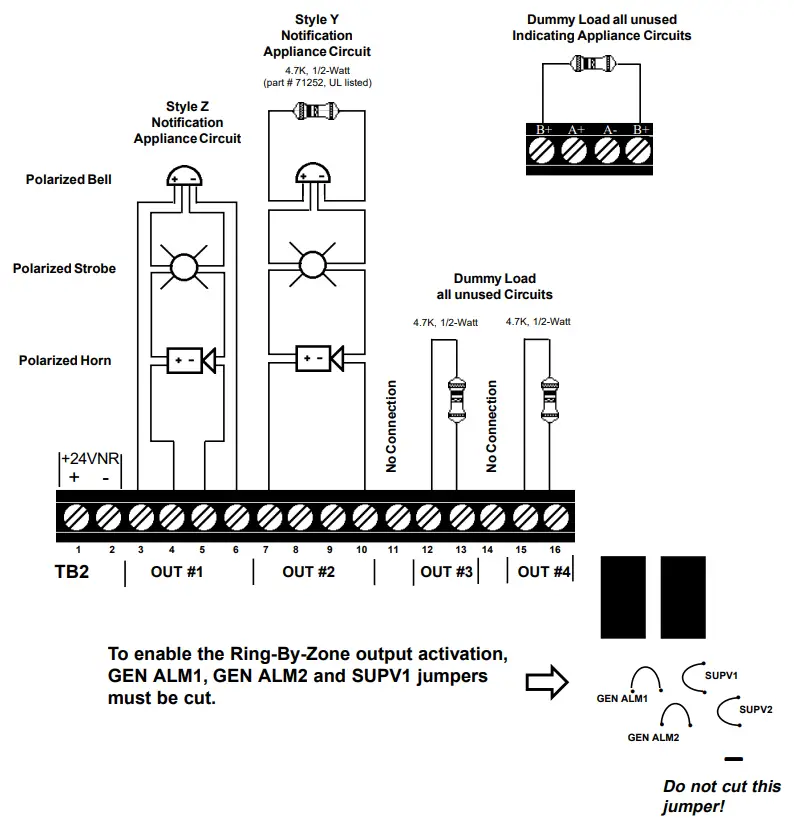
Output Circuits
Ring-By-Zone Feature
Outputs will function as General Alarm (all four outputs will be activated when any zone goes into alarm) unless the jumpers marked GEN ALM1, GEN ALM2 and SUPV1 are cut. DO NOT CUT the SUPV2 jumper. When these jumpers are cut, the Ring-By-Zone feature is enabled.
Supervisory Appliance Circuit
If Supervisory input is selected (see Section 3.7) and NO jumper is cut, all four Notification Appliance Circuits will activate for supervisory conditions. To activate only one Notification Appliance Circuit (Circuit 4), cut SUPV1 jumper. To disable all Notification Appliance Circuits, cut SUPV2 jumper for supervisory conditions. Refer to Jumper Configuration Table. (See figure on following page for jumper location.)
If a 4XZM relay module is used, relay 4 will activate for supervisory conditions.
If a RZA-4X is used, the red LED 4 will annunciate supervisory conditions.
Jumper Configuration Table
| Jumper Cut | Initiating Circuit Activated | Notification Appliance Circuits (X = output activated) | |||
| 1 | 2 | 3 | 4 | ||
| Gen Alm1 | 1 | X | |||
| Gen Alm1 | 2 | X | X | X | |
| Gen Alm1 | 3 | X | X | X | |
| Gen Alm1 | 4 | X | X | X | |
| Gen Alm2 | 1 | X | X | ||
| Gen Alm2 | 2 | X | X | ||
| Gen Alm2 | 3 | X | X | ||
| Gen Alm2 | 4 | X | X | ||
| Supv1 | 1 | X | X | X | |
| Supv1 | 2 | X | X | X | |
| Supv1 | 3 | X | X | X | |
| Supv1 | 4 | X | |||
| Supv2 | 1 | X | X | X | X |
| Supv2 | 2 | X | X | X | X |
| Supv2 | 3 | X | X | X | X |
| Supv2 | 4 | ||||
| Gen Alm1,Gen Alm2,Supv1 | 1 | X | |||
| Gen Alm1,Gen Alm2,Supv1 | 2 | X | |||
| Gen Alm1,Gen Alm2,Supv1 | 3 | X | |||
| Gen Alm1,Gen Alm2,Supv1 | 4 | X | |||
| None | 1 | X | X | X | X |
| None | 2 | X | X | X | X |
| None | 3 | X | X | X | X |
| None | 4 | X | X | X | X |
![]() 50368:A 12/04/95
50368:A 12/04/95
www.PDF-Zoo.com
firealarmresources.com


