![]()
DAYLIFF Circ 16 Smart Inline Boosting Pumps
Congratulations on selecting Dayliff CIRC 16 Smart Inline Boosting Pump. They are manufactured to the highest standards and if installed and operated correctly will give many years of tneicfeand trouble free service. Careful reading of this Installation Manual is therefore important, though should there be any queries they should be referred to the equipment supplier.
SPECIFICATIONS
PUMP
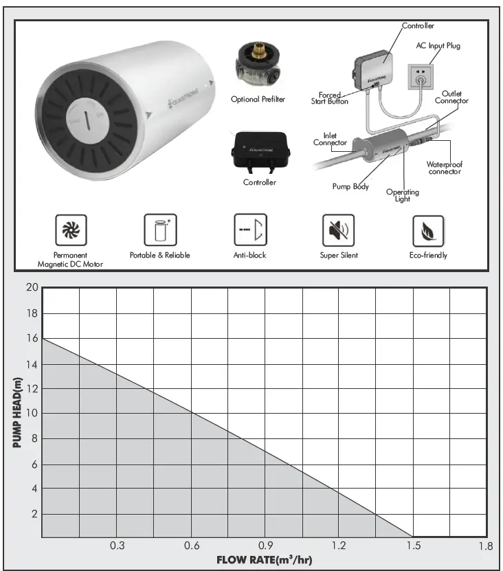
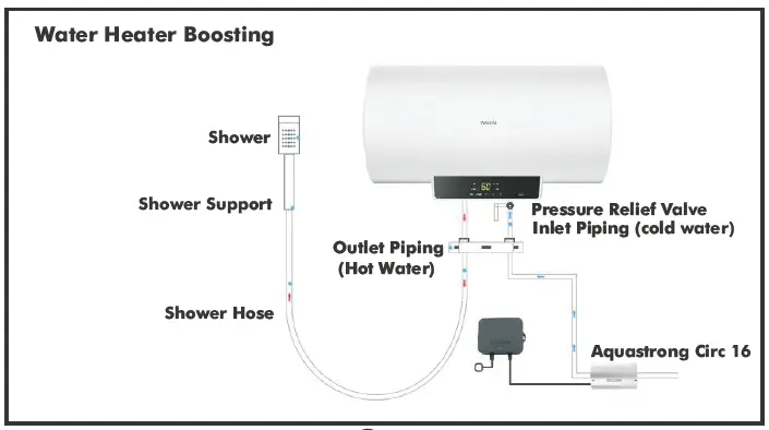
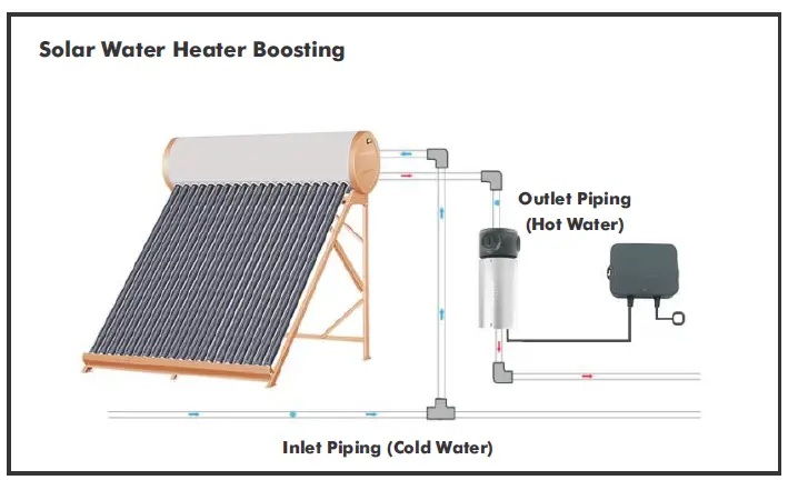
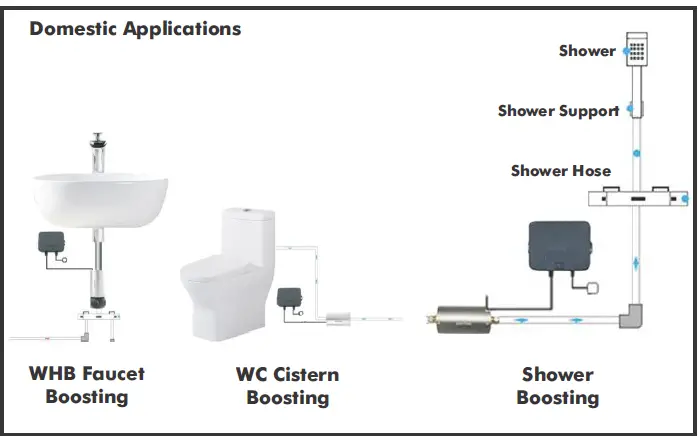
Dayliff Aquastrong CIRC 16 is a highly innovative smart inverter controlled water boosting pump suitable for various domestic applications including hot water circulation for electric or solar water heaters as well as shower and general tap pressure boosting. Particular features include:-
- Innovative inverter controlled Permanent magnet water cooled DC motor that features high efficiency and super silent (28dB) operation.
- Anti-block hydraulic design with large water passage and optional easy to clean prefilter.
- Suitable for all water temperatures up to 90
- Fully automatic operation with inbuilt flow switch control.
- Integrated Design using non corroding materials including an aluminium housing and engineering plastic hydraulic parts providing for up to 30,000 running hours operation.
- Extremely compact dimensions that enables simplified installation in confined spaces.
- Supplied complete with connectors, mounting brackets and separate inverter/controller unit.
- 2-year guarantee.
- Certified in accordance with the EU Uniform EN and the German Industrial DIN Standards.
Dayliff Aquastrong CIRC 16 is an exceptionally advanced product that uses state of the art inverter technology to provide the perfect solution to all domestic and residential water supply needs.
Insulation: F
Enclosure Class:IP57
Power: 96W, 175-245V, 50HZ/60HZ
Speed: 10,000rpm
OPERATING CONDITIONS
Pumped Liquid: Thin, clean, chemically non-aggressive liquids without solid
particles or fibers
Max. Ambient Temp: 50 C
Max. Liquid Temp: 90 C
Max Suction Lift: 0m (non-self-priming)
Start Flow: 1 l/min
Inlet/Outlet: ½”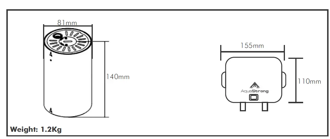
WARNINGS AND SYMBOLS
- The pump must not be installed against wood or any other material which may be affected by heat from the pump.
- Before installing the pump ensure all soldering/welding adjacent to the pump is complete, the system has been thoroughly dehsuout to remove any foreign matter and that vent and feed pipes are positioned so that the pump will not draw in air or over pump.
- The pump should not be installed in either a high point in the system where air can collect or a low point where sediments could build up.
- Pipes on both sides of the pump should be supported to reduce strain and must be correctly aligned prior to installing the pump to reduce the risk of scalding.
- Check the direction of woindicated by an arrow on the pump casing and install the pump between the isolating valves. When replacing a pump maintain the same direction of wo.
- Do not leave system empty without protection from corrosion. Ensure to use quality corrosion inhibitors.
- Non-approved replacement parts may not be used.
- Ensure no water leakage onto the pump motor or its electrical connections during installations, venting or operations as this may cause electrical shocks.
- Any action that doesn’t comply with safety warning sign may cause personal injury, pump damage and losses in property. Users must also comply with the local safety regulations.
- Electrical work to be carried out by a competent deilauq and licensed electrician.
INSTALLATION
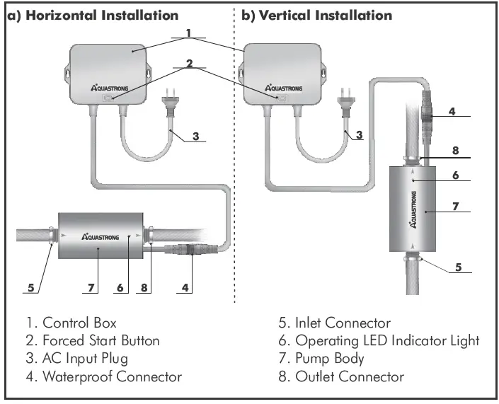
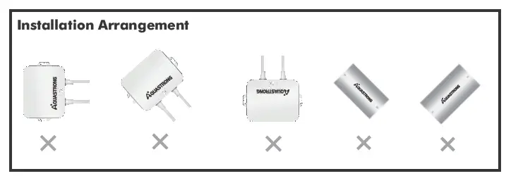
WARNING The pump and the controller must be installed either horizontally or vertically. Angled installations are not allowed.
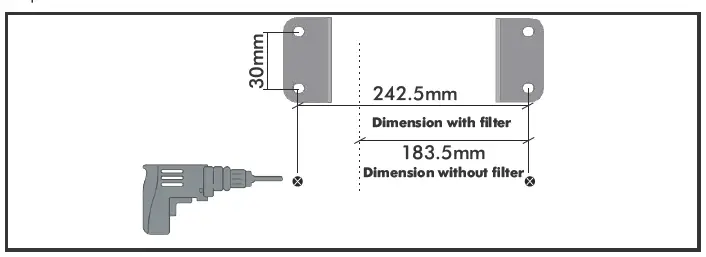
- Mark the location according to the bolt holes of the pump bracket and punch holes in the wall.

- Install the bracket and fix firmly on the wall
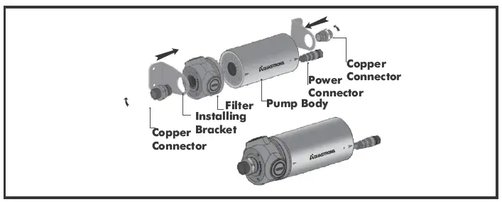
- Fix the pump into the pump bracket
- Fasten the copper connectors to the outlet and inlet by use of a wrench

- Connect the inlet and outlet to the pipe ensuring to fit isolating valves.

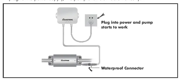
- Using the water proof connector, connect the controller to the pump and plug to the power supply, the pump shall start automatically.


APPLICATION


OPERATION
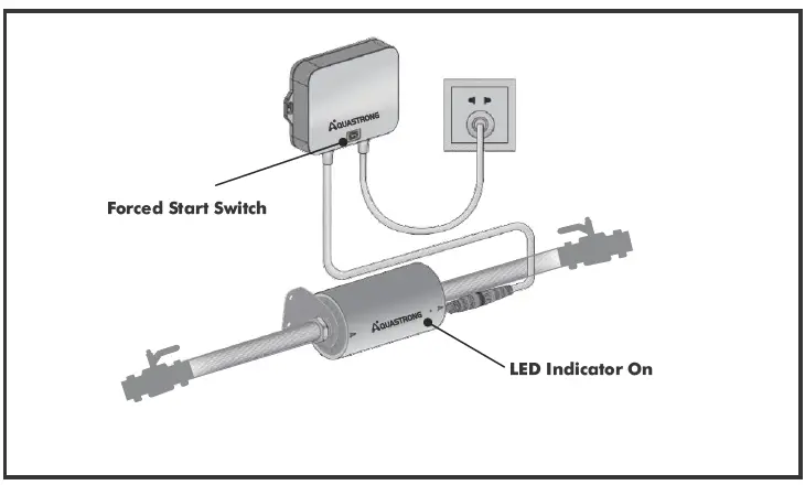
- The LED indicator light is always on when the pump is on automatic mode.
- The LED indicator light flashes continuously when the pump is on forced start mode .
- CIRC 16 will start and stop automatically due to inbuilt flow sensor.
- If the pump does not work due to water flow being lower than 1.0L/min, pressing the force start button can activate it.
- CIRC 16 will stop automatically after it runs for 20 minutes under the forced mode and switch to automatic mode.
NOTE
Circ16 does not have inbuilt dry running protection during operation. Ensure that there is no air in the pipeline to protect the pump from dry running.
TROUBLESHOOTING
| Problem | LED Indicator Light | Errors | Main Problems | Solutions |
|
Pump not working | LED Indicator flashes once | Overvoltage or Undervoltage | Controller faulty | Replace the controller |
| LED Indicator flashes twice | Overcurrent | Controller faulty | Replace the controller | |
|
LED Indicator flashes thrice |
Overcurrent | Impeller stuck due to debris | Disassemble the pump and clean | |
| Rotor damaged | Replace the motor | |||
|
LED Indicator flashes four times | Flow sensor damaged | The flow sensor is jammed and cannot open properly | Disassemble the pump and clean | |
| Flow sensor damaged | Replace the sensor | |||
| LED Indicator flashes five times |
Water Shortage | No water in the pipeline | Start the pump when water supply resumes | |
| Air in the pipeline | Empty the pipeline | |||
| Pump does not stop |
None | Pump running continously | The flow sensor is jammed with debris | Disassemble the pump and clean |
| Controller is damaged | Replace the controller | |||
|
Pump vibration with high noise |
None |
Loud Vibrations | Debris in the pump body | Clean the debris in the pump chamber |
| Air in the pipeline | Open the tap and eliminate air | |||
| Rotor is worn out | Replace the rotor |
TERMS OF WARRANTY
- General Liability
- In lieu of any warranty, condition or liability implied by law, the liability of Dayliff (hereafter called the Distributor) in respect of any defect or failure of equipment supplied is limited to making good by replacement or repair (at the Distributor’s discretion) defects which under proper use appear therein and arise solely from faulty design, materials or workmanship within a specified period. This period commences immediately after the equipment has been delivered to the customer and at its termination all liability ceases. Also the warranty period will be assessed on the basis of the date that the Distributor is informed of the failure.
- This warranty applies solely to equipment supplied and no claim for consequential damages, however arising, will be entertained. Also the warranty specifically excludes defects caused by fair wear and tear, the effects of careless handling, lack of maintenance, faulty installation, incompetence on the part of the equipment user, Acts of God or any other cause beyond the Distributors’s reasonable control. Also, any repair or attempt at repair carried out by any other party invalidates all warranties.
- Standard Warranty
If equipment failure occurs in the normal course of service having been competently installed and when operating within its specified duty limits warranty will be provided as follows:-- Up to one year- The item will be replaced or repaired at no charge.
- Over one year, less than two years – The item will be replaced or repaired at a cost to the customer of 50% of the Davis & Shirtliff market price.
The warranty on equipment supplied or installed by others is conditional upon the defective unit ec fo ffiltrihS & sivaD a ot eerf denruter yltpmorp gnieb and collected thereafter when repaired. No element of site repair is included in the warranty and any site attendance costs will be payable in full at standard charegeout rates. Also proof of purchase including the purchase invoice must be provided for a warranty claim to be considered.


