![]()
![]()
23 November 2021
EdgeSync
Network Timing Edge Device
User Manual
EdgeSync and EdgeSync+
Document Part No: 1244-5000-0050
Revision: 2
Introduction
Functional Overview
The EdgeSync is a small form factor, highly accurate Multi-Sync Gateway that provides IEEE 15882008 PTP Grand Master and Boundary Clock functionality. IEEE 1588-2008 PTP is also known as PTP Version 2.
EdgeSync gets its time from the built-in GNSS receiver or 1PPS/ToD input or IEEE 1588-2008 PTP as input references. PTP algorithms are leveraged to deliver stringent timing for frequency and phase profiles. Outputs include IEEE 1588-2008 PTP, selectable FREQ Out, 1PPS, and Time of Day (ToD). EdgeSync will provide holdover depending on the chosen built-in oscillator.
Remote control and monitoring are provided over SSH, Web Interface and SNMP (v2, v3).
Interfaces
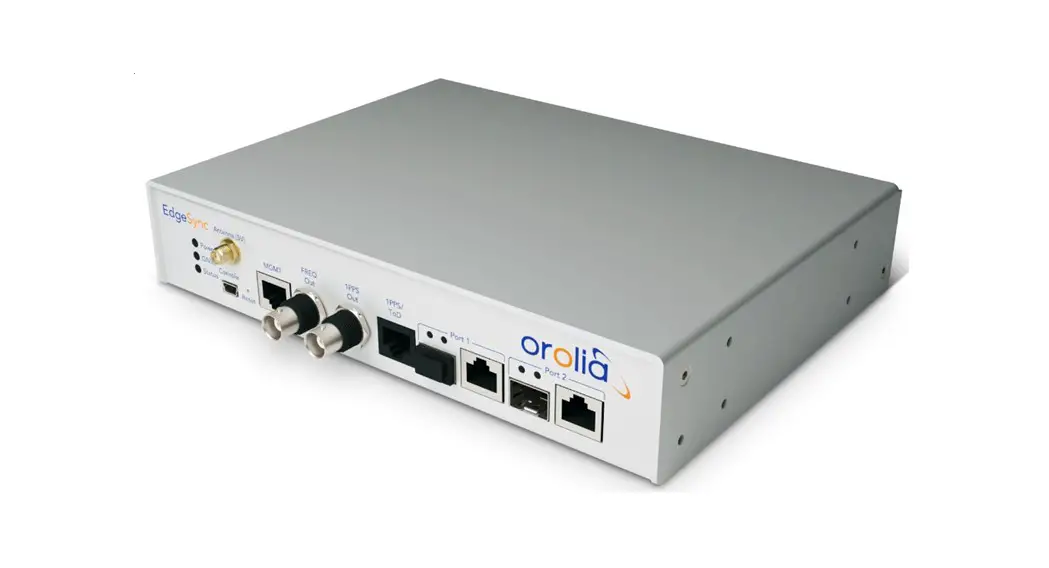
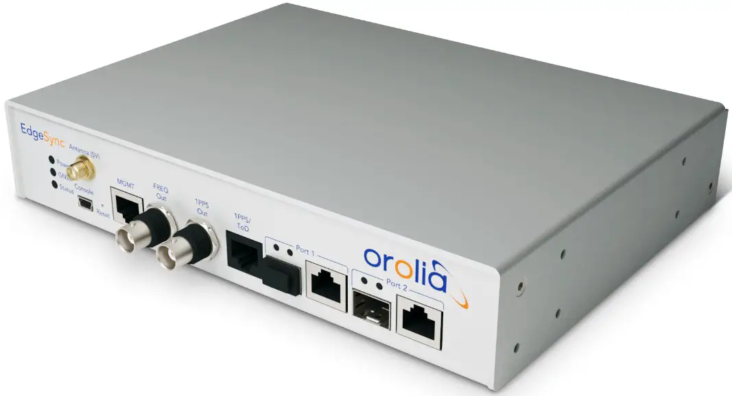
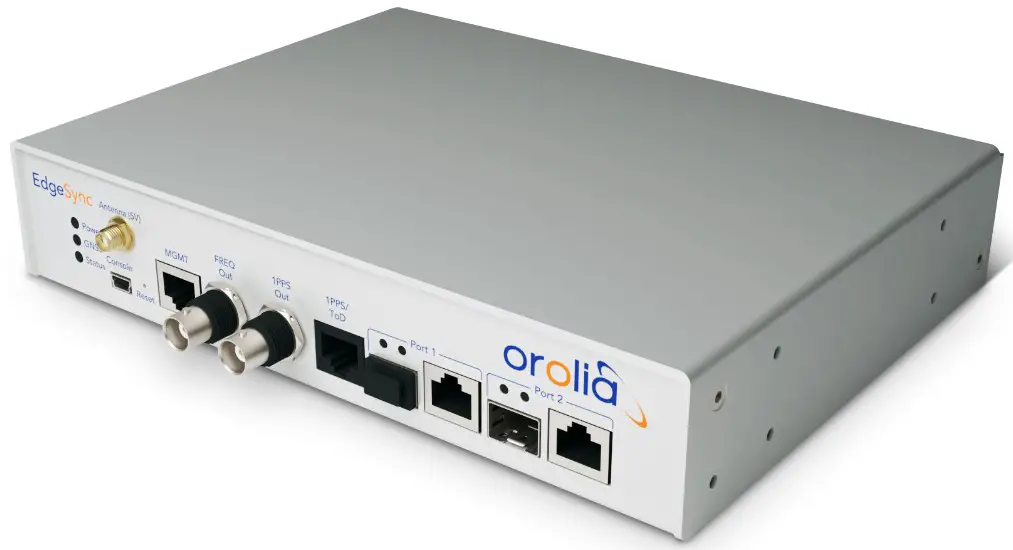
EdgeSync Interfaces are shown in following images, along with a brief description of them in the tables below them. Detailed description of the interfaces is provided in the REF section of this User Guide
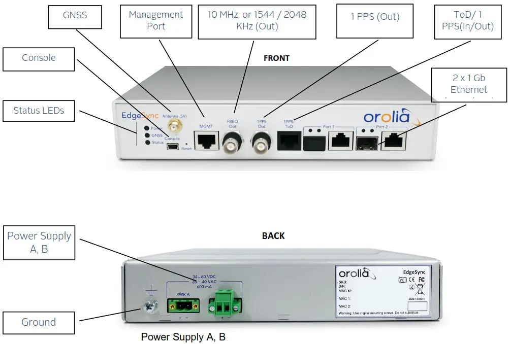
| Rear Panel Description |
| Ground connector |
| Primary power plug, 34 – 60 VDC / 28 – 40 VAC |
| Secondary power plug, 34 – 60 VDC / 28 – 40 VAC |
Table 1 EdgeSync Rear Panel Interfaces
Typical Applications
EdgeSync is a small form factor IEEE-1588-2008 PTP Edge Grand Master and Boundary Clock that can be used for smart grid transmission and distribution substations. This Multi-Sync Gateway platform is designed for small cell clusters, C-RAN, and edge applications. For more information
Oscillator Options
EdgeSync: OCXO oscillator, 4-hour holdover for 1.5 µsec accuracy.
EdgeSync+: HP OCXO oscillator, 8-hour holdover for 1.5 µsec accuracy.
PTP Slave Capacity
The EdgeSync has two variants that can support different unicast slave capacity (32 or 128) slaves at up to 128 sync / delay packets per second when the Managed Clock Engine (MCE) is operated as a master clock depending on the product SKU. The variants are configured at the factory and cannot be field upgraded at present. Section 10 of this User Guide presents the two variants available.
Components Block Diagram
The following block diagram defines the main components of the EdgeSync system along with the physical connections to each component.
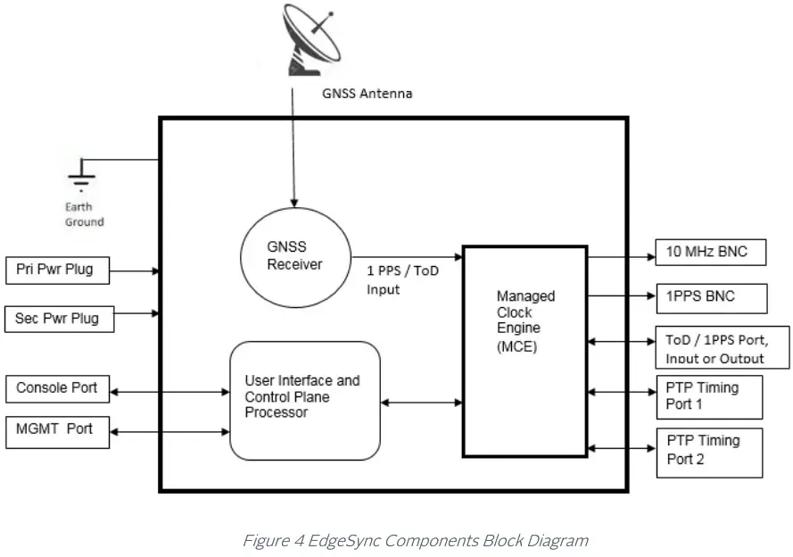
- Managed Clock Engine (MCE) is a full packet network-based synchronization engine supporting IEEE 1588-2008 Precise Time Protocol. The MCE is where IEEE 1588-2008 PTP packet communication processing runs, and port / BNC provisioning is applied. GNSS signals and User Interface Processor (UIP) commands are sent to the MCE.
- User Interface and Control Plane Processor, which supports all the user access and connectivity to the entire system. The Processor supports DHCP, HTTP webpage/CLI access, SSH, SFTP, XML and SNMP (v2, v3).
- GNSS Receiver GPS Receiver combined with either a Beidou or Glonass or Galileo Receiver with external antenna input. The selection of the constellation is user configurable.
Installation
Before the EdgeSync is installed, review the information in this section. If difficulties are encountered during the installation process, contact Orolia Customer Support, with the contact information provided in the Contact Section of this User Guide.
Security Recommendations
The EdgeSync Management port and PTP Timing ports should be installed behind the company’s firewall to prevent public access. Additionally, the PTP Timing ports should be connected to a Local Area Network (LAN) or Wide Area Network (WAN) dedicated to transporting PTP timing messages.
Environmental Requirements
The EdgeSync operating temperature is 0°C to 50° C (32°F to 122° F). Use only shielded cable for all signal wiring, including I/O, clocks and Ethernet. Use the Ground connector to appropriately ground the EdgeSync to earth ground.
Packaging List and Unpacking
The EdgeSync box contains the following:
- The EdgeSync Multi-Sync Gateway
- AC/DC power supply and spare terminal block connector
GNSS antenna and accessories, rack mounting bracket and secondary AC/DC power supplies are available.
The EdgeSync is packaged to be protected from normal shock, vibration, and handling damage during shipment. Unpack and inspect the box contents as follows:
- Wear a properly grounded protective wrist strap or suitable ESD protection.
- Inspect the shipping box for signs of damage. If the box appears to be damaged, notify both the carrier, and Orolia or your Orolia distributor. Retain the shipping box and packaging material for the carrier to inspect.
- Open the box, being careful to cut only the packaging tape.
- Locate and save the printed packaging list and paperwork that is included in the box.
- Remove the EdgeSync from the box and place the unit on an anti-static surface.
- Locate and set aside additional parts which may be contained in the box.
- Remove and dispose of the anti-static packaging from the EdgeSync and parts.
- Verify that the model and serial number shown on the packaging list agrees with the model and serial number on the EdgeSync. The model number can be found on a label affixed on the back of EdgeSync. Contact Orolia or your Orolia distributor if the model or serial number do not match.
Rack Mounting the EdgeSync
The EdgeSync is half of a 19-inch rack, and occupies 1.75 in (4.5 cm, 1RU) of vertical rack space. An optional mounting bracket is available.
Warning: When rack mounting the EdgeSync, use the original mounting screws provided with the mounting bracket so that the EdgeSync case will not be damaged. Do not substitute other mounting screws.
Power and Ground Connections
Power
The EdgeSync uses two VDC power sources, primary and backup. One or both power sources can be used. The power source can be 34 60 VDC. The VDC power connector uses two power feed lines, PWR A and PWR B. EdgeSync comes equipped with 2 Phoenix connectors to supply PWR A and PWR B and the user needs to connect the two terminals of it to their DC +/- supplies. The EdgeSync can also be powered by two VAC power sources, with 28 40 VAC supply.
IMPORTANT NOTE:
All operation, test and performance references and specifications that Orolia, Inc. makes in its EdgeSync customer documents, and on its label, and to certification authorities are based on actual measurements ONLY when operated with the power supplies that Orolia provides or offers as an optional accessory. If operated with other brands and/or different specifications of power supplies, Orolia will NOT guarantee EdgeSync’s proper operation, functionality or its compliance with the stated standards!
Ground
The EdgeSync ground is a 4 mm ground stud and is identified with the international ground marking as shown on Figure 3. This ground wire should be routed to earth ground.
Input / Output Signal Connections
Management
Using a standard CAT5 cable, connect the cable to the port labelled MGMT of the front panel to your network. The data rate is 10/100 Base-T shielded RJ45 receptacle. The Management port supports both forms of IP address assignment, static or DHCP.
Console
A mini-USB connector labelled Console is available for EdgeSync to have a serial connection to a PC or laptop. The user can connect to EdgeSync console via terminal emulation applications on PC like Tera Term, PuTTy, minicom or Procomm to access the CLI over the serial port.
FREQ Out
BNC connector to port labelled FREQ Out to provide syntonized selectable frequencies output from EdgeSync. The FREQ Out is DC Blocked.
Timing outputs, 1PPS A configurable 1PPS is provided on a BNC connector, labelled 1PPS. Connect the 1PPS signal output to a frequency counter or any other measuring device.
Timing inputs/outputs, ToD / 1PPS
An RJ45 port is provided, labelled ToD / 1PPS. These ports are configurable to provide input or output for ToD / 1PPS. Both, the ToD format and the 1PPS signal are configurable. Refer to [2] for details of the timing ports physical/electrical characteristics.
PTP Port 1 and Port 2
One shielded RJ45 copper port and one SFP port is provided in parallel for Port 1. Likewise, one shielded RJ45 copper port and one SFP port is provided in parallel for Port 2. These ports provide PTP protocol messages to the timing network. See Gateway and Boundary clock Section of this User Guide for information on how the PTP Port 1 and Port 2 perform when the Clock Type Mode is configured as Gateway or Boundary clock. Selecting the Clock Type Mode is described in the PTP :: Clock Section of this User Guide.
Connecting GNSS Antenna
Connect a suitable GNSS antenna, making sure the antenna has a clear view of the sky. When the GNSS receiver has good reception, the GNSS LED will be green. EdgeSync provides 5.0 VDC bias to power remote active antennas.
The GNSS antenna connector is a female SMA with external threads. Once the GNSS antenna is connected to EdgeSync antenna port, the GNSS operation can be configured and monitored in the Interface :: GNSS Section of this User Guide.
Applying Power
EdgeSync does not have a power switch, so power should not be applied until the Ground connector is installed and connected to earth ground. To avoid accidental power up of the EdgeSync, please recheck and ensure all connections are made including the Ground connector, before enabling external power to EdgeSync.
Getting Started
This chapter describes on how the user can start using EdgeSync system after installing EdgeSync device and making the necessary connections to the various hardware interfaces.
Logging in with the console
Log into EdgeSync using the mini-USB console. Default set-up is 115200 baud, 8 bits, no parity, and one stop bit. Login is admin and password are admin. Terminal emulation software like Tera Term, PuTTY, minicom and Procomm can be used for this purpose.
Set up IP address
The Management port IP address assigned to the EdgeSync can be viewed using the mini-USB console.
At the factory, the EdgeSync Management port IP is statically assigned to 192.168.2.100 with netmask of 255.255.255.0. This static IP address will be set after doing a restore to factory default configuration. To configure the Management port IP address for customer network:
- Connect the EdgeSync mini-USB console port to a PC and run a terminal emulator application (Tera Term, PuTTY, minicom, Procomm, etc.) to login to the EdgeSync. Login credentials are provided in the EdgeSync Basic Commands section. Use the “network configure” command to configure the Management port IP parameters. The Network Configure Command section provides CLI command details for setting the Management port IP address, subnet mask and Gateway IP.
- With the Management port IP address configured successfully, the IP address can be entered into a browser URL field to access the EdgeSync Login page, with login credentials (admin/admin).
Remote Network Access to EdgeSync
EdgeSync can be accessed remotely over IP network via the Management IP Interface. These are some of the methods to access EdgeSync remotely:
HTTP/Web access
EdgeSync can be accessed over the web from any standard browser (IE, Chrome, Firefox, Safari, etc.). This provides a Graphical User Interface (GUI) for the user to configure or monitor EdgeSync operations.
The following web browsers / versions are supported by the EdgeSync HTTP server:
- Internet Explorer / v11.0.31
- Chrome / v63.0.3239.132
- Firefox / v56.0
- Safari / v11.0.3
Secure Shell (SSH) access
SSH offers a secure shell for users to do remote login to EdgeSync using terminal emulation software. After login, the user can use EdgeSync CLI to send commands. Note that only SSH and not Telnet access is allowed for remote shell login.
SNMP (v2, v3)
EdgeSync can be one of many managed devices on the network with an Element Management System (EMS) or Network Management System (NMS) as the centralized server. Currently, only SNMP is supported for PTPBASE-MIB specification from Timing Over IP Connections and Transfer of Clock (TICTOC) Working Group. The text format of PTPBASE-MIB can be downloaded from https://files.spectracom.com/public-downloads/edgesync-snmp-mib
XML API
Applications using XML interface can access EdgeSync system via its XML API’s. Support for this will be added in future release.
Web Interface
This chapter deals with the Web Interface of EdgeSync. A topic for each page in the web interface is provided, with an explanation of each tab, button and selection on each page. The Login Webpage and Home Webpage are presented as a starting point for accessing the Web Interface.
Login Webpage
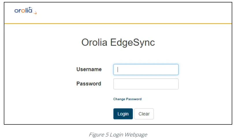
The Login webpage contains the following entries and buttons:
- Username (Factory default: “admin”)
- Password (Factory default: “admin”)
- Change Password hyperlink, selects Change Password webpage
- Login button Apply Username and Password to login
- Clear button Clear Username and Password
Change Password Webpage
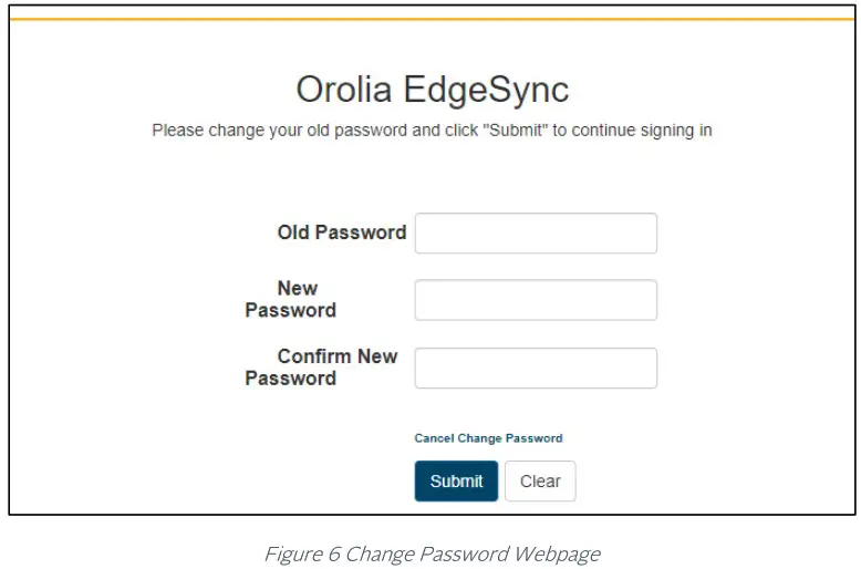
The Change Password webpage contains the following entries and buttons:
- Old Password Enter current password
- New Password Enter new password
- Confirm New Password Re-enter new password
- Cancel Change Password hyperlink, selects Login webpage
- Submit button Apply New Password
- Clear button Clear all entries
Hard Reset Button section of this User Guide describes how to reset the EdgeSync to factory defaults. When the EdgeSync completes the reboot, the password will be reset back to “admin”. Prior to doing a Hard Reset, saving the current configuration of the EdgeSync is recommended, and then reloading the configuration after reboot has completed.
Home Webpage
Prior to starting the Timing Engine, some basic configurations are needed to define the clock, the mode of operation and user deployment scenario. These basic configurations are provided inside the box at the top of the Home page.
(PTP) Profile dropdown selections
- Default profile (1588_V2)
- Telecom profile
- G8275.1 (frequency + phase, L2 multicast, requires full on-path timing network support)
- G8275.2 (frequency + phase, L3 unicast, for partial timing network)
- G8265.1 (frequency only from packet network)
- Power_V1 (IEEE C37.238-2011)
- Power_V2 (IEEE C37.238-2017)
- Power Utility (IEC61850-9-3:2016)
- SMPTE profile
- ST 2059-2:2015 – SMPTE Profile for Use of IEEE-1588 Precision Time Protocol in Professional Broadcast Applications.
Operating Mode dropdown selections
- PTP Only · GNSS Only
- GNSS Primary, PTP Secondary
- PTP Primary, GNSS Secondary
- PTP only, GPS debug (experimental, for Orolia internal use ONLY!)
EdgeSync Operating Modes are described in detail and can be managed as described in the
EdgeSync Engine Modes Section of this User Guide.
Clock Type dropdown selections
- Ordinary Clock (Grandmaster, Master, Slave)
- Boundary Clock (one port is Slave, and the other port is Master)
Network Type dropdown selections (to optimize for user network conditions)
- Unmanaged (networks with unknown packet delay variation)
- Managed (networks with distinct floor of minimum packet delay variation)
- Full on-path (networks as specified in G.8275.1, to comply with G.8273.2 for frequency response specification. NOTE: The slave Start and Main Time Constant values will be optimized to 100 and 1 when Full on-path support is configured
EEC Option dropdown menu (EEC = Ethernet Equipment Clock, with accuracy within ±4.6 ppm)
- Option-1 (for 2048 kbps network hierarchy, min BW = 1Hz, max BW = 10Hz, Europe)
- Option-2 (for 1544 kbps network hierarchy, min BW = none, max BW = 0.1Hz, N America)
- eEEC Option-1 (enhanced EEC bandwidth with Option-1)
- eEEC Option-2 (enhanced EEC bandwidth with Option-2)
Note: eEEC bandwidth option that can be combined with Option-1 (Europe) or Option-2 (N America).
Synchronous Ethernet dropdown menu
- OFF (Synchronous Ethernet is disabled, no clock recovery from either port, no ESMC processing or transmit, only PTP operation)
- GM GNSS Source (no clock recovery from ports, ref frequency from 1pps used for SyncE out (Ethernet Tx clock, ESMC/QL out on both ports), plus PTP operation)
- BC Ref input port-1 (SyncE in (recovered clock, input ESMC/QL) from port-1, SyncE out on port-2, plus PTP operation. For G8275.2 profile, SyncE out is disabled)
- BC Ref input port-2 (SyncE in (recovered clock, input ESMC/QL) from port-2, SyncE out on port-1, plus PTP operation. For G8275.2 profile, SyncE out is disabled)
NOTE:
- The above configurations that are encapsulated in the box on the Home webpage need to be configured BEFORE starting the timing engine. These configuration parameters in the box defines the basic mode of operation in customizing for customer deployment and application.
- Once the engine is stopped to change the profile or other configuration within this box, some of the timing engine related configuration may get reset to default values.
- Synchronous Ethernet is supported only for the following Operating Modes:
a. PTP Only, and
b. GNSS Only
Start Engine/Stop Engine
- Click the button to start Clock Engine if the engine is stopped, or stop it if it is already running. While the engine start is in progress, a label will display “Applying configuration and starting the engine – please wait!!” at the top of the screen.
Clock ID
- This is this EdgeSync node’s PTP Clock-Id.
Time Source
- GNSS
- PTP
PTP Sync (Status / State)
- Status can be “Locked” or “Unlocked”
- State can be
- Free Running no reference clock source, using internal oscillator
- Syntonizing 1pps reference but no reference ToD source, frequency only
- Synchronizing (1pps + ToD) or PTP reference source, timing synchronized to that
- Holdover Lost reference source, timing continues with earlier reference
EdgeSync Sync States are described in detail in the EdgeSync Clock Sync States Section of this User Guide.
GNSS Status (1PPS / ToD)
- Stable
- Unstable
UTC Time
- Format YYYY-MM-DD HH:MM:SS
- This is also known as Greenwich Mean Time (GMT) or Zulu time.
PTP Time
- Format YYYY-MM-DD HH:MM:SS:<fraction of a second>
Local Time
- Format YYYY-MM-DD HH:MM:SS <xxT>
- Can be customized to local time zone using “Local TZ” configuration
- Default setting is the same as UTC Time (i.e.. “GMT”)
Local TZ (time zone)
User can select one of many pull-down options to select the appropriate time-zone for the local time.
- (GMT +0:00) UTC, GMT, WET
- (GMT -11:00) MIT
- (GMT -10:00) HST
- (GMT +11:00) SST
- (GMT +12:00) NST
Daylight Saving
- Enable Daylight Saving
- Start Time: Month [Jan-Dec], Week [1..4, last], Day [Sun Sat], Hour [0-23], Min [0, 15, 30, 45]
- End Time: Month [Jan-Dec], Week [1..4, last], Day [Sun Sat], Hour [0-23], Min [0, 15, 30, 45]
Logout Button Logs the user out of the EdgeSync Web server.
Interface Webpage Tab
Interface Dropdown selections
- PTP Timing Ports
- MGMT Port
- GNSS
- ToD/1PPS Output
Interface: PTP Timing Ports
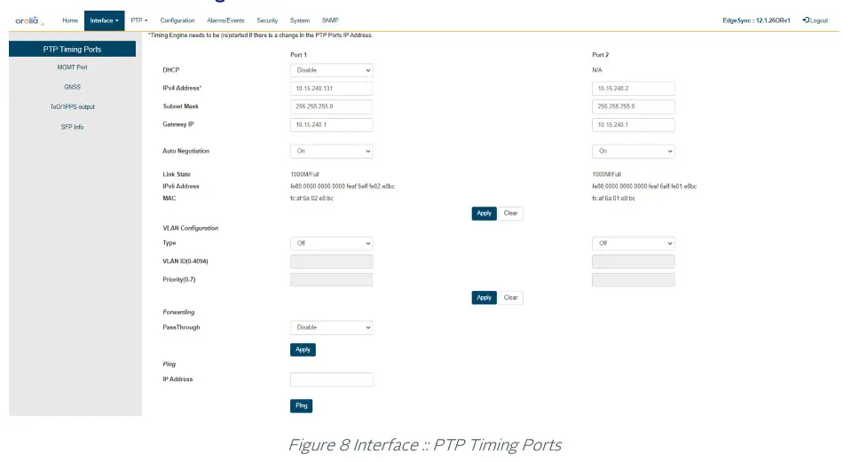
The PTP Timing Ports webpage contains the following displays, selections, entries, and buttons:
| PTP Timing Ports Legend: RO = Read Only, RW = Read/Write, WO = Write Only | ||
| Labels | Access | Description |
| PTP Timing Ports – Port 1 | ||
| DHCP | RW | Enable / Disable DHCP for dynamic IP assignment |
| Ipv4 Address | RW | Four dot separated octets (0 – 255) for static IP assignment |
| Subnet Mask | RW | Four dot separated octets (0 – 255) for static IP assignment |
| Gateway IP | RW | Four dot separated octets (0 – 255) for static IP assignment |
| Auto Negotiation | RW | Drop down menu for IEEE 802.3 Ethernet link auto-negotiation. Drop down menu options: On 1000 Full Duplex 1000 Half Duplex 100 Full Duplex 100 Half Duplex 10 Full Duplex 10 Half Duplex NOTE: Synchronous Ethernet is supported only for 1000 Full Duplex ports |
| Link State | RO | Link Up / Link Down Status with Mbps Data Rate and Full-Duplex I/O |
| IPv6 Address | RO | (Link-local) IPv6 address used when PTP::Port::Network Protocol is IPv6 |
| MAC | RO | Six colon separated hexadecimal MAC address display |
| PTP Timing Ports – Port 2 | ||
| DHCP | N/A (DHCP supported only for Port 1) | |
| Ipv4 Address | RW | Four dot-separated octets (0 – 255) |
| Subnet Mask | RW | Four dot-separated octets (0 – 255) |
| Gateway IP | RW | Four dot-separated octets (0 – 255) |
| Link State | RO | Link Up / Link Down Status with Mbps Data Rate and Full Duplex I/O |
| IPv6 Address | RO | (Link local) IPv6 address used when PTP::Port::Network Protocol is IPv6 |
| MAC | RO | Six colon separated hexadecimals |
| Apply / Clear | ||
| Apply Button | WO | Click for selection and Timing Port settings to be applied to EdgeSync |
| Clear Button | WO | Click to clear the recent changes |
| VLAN Configuration – Port 1 | ||
| Type | WO | Select Off / None / VLAN Off – Send and receive untagged frames only None – Send untagged frames, receive untagged frames and priority tagged frames VLAN – With Priority 0, send priority tagged frames, receive untagged and priority tagged frames VLAN – With VLAN ID and Priority 1 to 7, send and receive VLANtagged frames only |
| VLAN ID (04094) | WO | Set VLAN ID |
| Priority (0-7) | RW | Set VLAN Priority |
| VLAN Configuration – Port 2 | ||
| Type | RW RW | Select Off / None / VLAN Off – Send and receive untagged frames only None – Send untagged frames, receive untagged frames and priority tagged frames VLAN – With Priority 0, send priority tagged frames, receive untagged and priority tagged frames VLAN – With VLAN ID and Priority 1 to 7, send and receive VLANtagged frames only |
| VLAN ID (04094) | RW | Set VLAN ID |
| Priority (0-7) | RW | Set VLAN Priority |
| Apply / Clear | ||
| Apply Button | WO | Click for selection and VLAN settings to be applied to EdgeSync |
| Clear Button | WO | Click to clear recent changes |
| Forwarding | ||
| PassThrough | RW | Enable: All packets (including user data) received on the PTP port(s) that is not destined for this EdgeSync will be forwarded from one PTP port to another PTP port. Disable: Only (PTP) traffic destined for this EdgeSync will be processed. All other traffic will not be forwarded to the other port and will be dropped/terminated. |
| Ping | ||
| IP Address | RW | Four dot separated octets (0 – 255) IP to ping |
| Ping Button | WO | Click to ping to the entered IPv4 address (support for IPv6 in a future release) |
Interface : MGMT Port
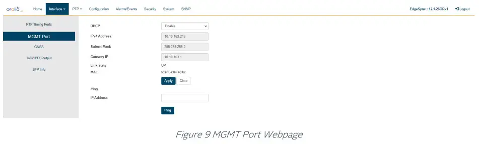
The MGMT Port webpage contains the following displays, selections, entries, and buttons:
| Interface: MGMT Port Legend: RO = Read Only, RW = Read/Write, WO = Write Only | ||
| Labels | Access | Description |
| MGMT Port | ||
| DHCP | RW | Enable / Disable DHCP for dynamic IP assignment |
| Ipv4 Address | RW | Four dot separated octets (0 – 255) for static IP assignment |
| Subnet Mask | RW | Four dot separated octets (0 – 255) for static IP assignment |
| Gateway IP | RW | Four dot separated octets (0 – 255) for static IP assignment |
| Link State | RO | Link UP / Link DOWN Status |
| MAC | RO | Six colon separated hexadecimal MAC address display |
| Apply / Clear | ||
| Apply Button | WO | Click for selection and settings to be applied to the EdgeSync MGMT port |
| Clear Button | WO | Click to clear the latest changes |
| Ping | ||
| IP Address | RW | Four dot separated octets (0 – 255) IP to ping |
| Ping Button | WO | Click to Ping to the entered IP address |
Table 3 Management Port Options
Interface: GNSS
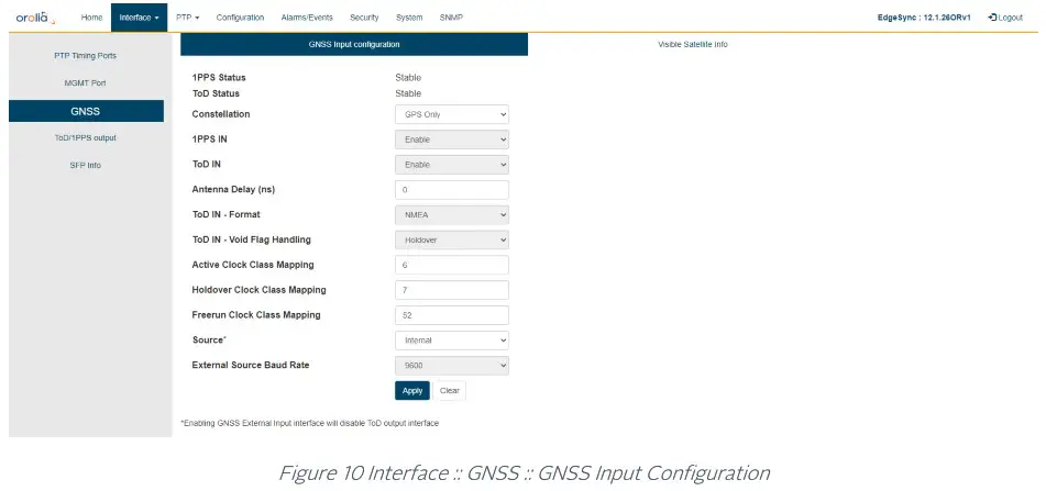
The GNSS webpage contains the following displays, selections, entries, and buttons:
| Interface:: GNSS Legend: RO = Read Only, RW = Read/Write, WO = Write Only | ||
| Labels | Access | Description |
| GNSS | ||
| 1PPS Status | RO | 1 pulse per second (1PPS) Stable or Unstable |
| ToD Status | RO | Time of Day (ToD) Stable or Unstable |
| Constellation | RW | Selection of one GNSS constellation option: • GPS-only • GPS + Glonass • GPS + Beidou • GPS + Galileo |
| 1PPS IN | RW | Enable/Disable of 1PPS from external GNSS Receiver |
| ToD IN | RW | Enable/Disable of ToD from external GNSS Receiver |
| Antenna Delay (ns) | RW | Calibration for cable delay in nano-seconds. Range [0 —2147483647] |
| ToD IN – Format | RW | Format of ToD message — NMEA, ASCII, or China Mobile |
| ToD IN — Void Flag Handling | RW | Option for handling Void (V) flag in RMC data in GNSS message. Options are Ignore: Ignore the Void flag in RMC and treat as Active (A) Syntonize: Do not ignore but accept 1PPS only as valid Holdover: Do not ignore Void flag and treat as not Active |
| Active Clock Class Mapping | RW | GNSS Active (A) clock class. The allowed Clock Class settings are defined in IEEE Std 1588-2008, section 7.6.2.4 and Table 5. |
| Holdover Clock Class Mapping | RW | GNSS Holdover clock class. The allowed Clock Class settings are defined in IEEE Std 1588-2008, section 7.6.2.4 and Table 5. |
| Freerun Clock Class Mapping | RW | GNSS Freerun clock class. The allowed Clock Class settings are defined in IEEE Std 1588-2008, section 7.6.2.4 and Table 5. |
| Source | RW | GNSS ToD/1PPS source: Internal or External Note: Selecting External will disable ToD and 1pps outputs as the same interface is used for both, input and output. |
| External Source Baud Rate | RW | GNSS ToD Baud Rate: 4800 or 9600 |
| Apply / Clear | ||
| Apply Button | WO | Click for selection and settings to be applied to the EdgeSync |
| Clear Button | WO | Click to clear the latest changes |
Table 4 GNSS Options
IMPORTANT NOTE on GNSS Clock Class mapping: :
By default, EdgeSync software will set the default configuration of GNSS Clock Class Mapping as: 6 for Active, 7 for Holdover, and 52 for Freerun. This is correct when the Engine Operating Mode (on the Home webpage) is set to GNSS-Only.
Please follow this table in setting up the GNSS Clock Class Mapping for the different Engine Operating Modes. This is important, to ensure proper operation of the timing engine in different operating modes.
| Operating Mode | Clock Active | Clock Class Mapping | Comment | |
| Holdover | Freerun | |||
| PTP Only | 6 | 7 | 52 | Don’t care – use default |
| GNSS Only | 6 | 7 | 52 | Use default |
| GNSS Primary, PTP Secondary | 6 | 7 | 187 | Freerun => 187 |
| PTP Primary, GNSS Secondary | 6 | 7 | 187 | Freerun => 187 |
| PTP only, GNSS debug | 6 | 7 | 52 | Use default |
Table 5 GNSS Clock Class Mapping configuration
Interface: GNSS Visible Satellite Info
Informational parameters of all the visible satellites are displayed on selecting this tab. Also, the physical geographical location & fix quality is displayed.
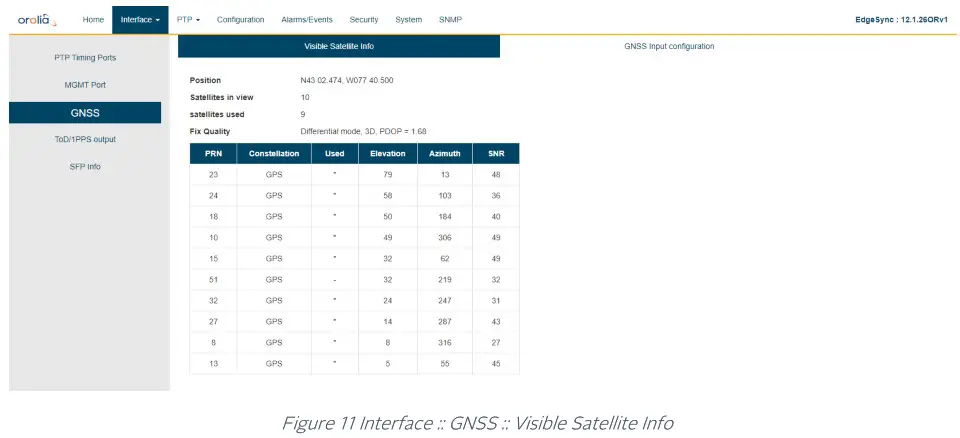
NOTE :
- The Visible Satellite Info field will get updated as constellations/satellites come into view. If user configures a different new constellation at run-time, some of the old stale information may still be displayed. This will be cleared on a reboot.
Interface :: ToD/1PPS Output
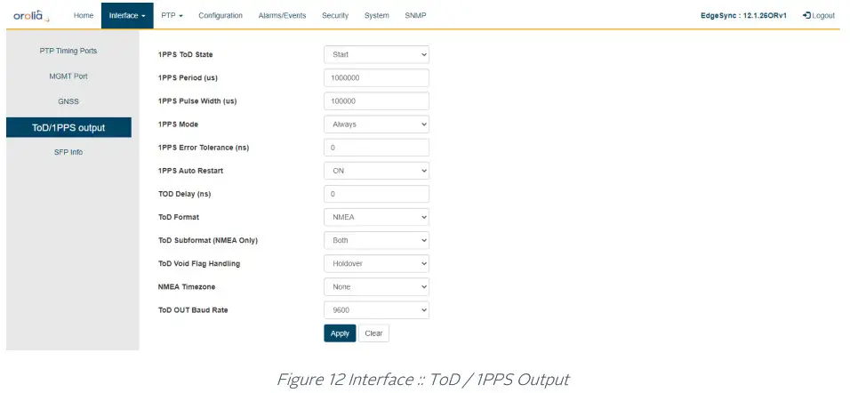
The ToD / 1PPS Output webpage contains the following selections, entries, and buttons:
Interface :: ToD / 1PPS Output
| Interface :: ToD / 1PPS Output Legend: RO = Read Only, RW = Read/Write, WO = Write Only | ||
| Labels | Access | Description |
| GNSS | ||
| 1PPS State | RW | Stop/Start control of 1PPS output |
| 1PPS Period (us) | RW | 1PPS pulse period in micro-seconds. Typically, one second but can be configured to be different. Range: 1000000 to 4294967295 (or – 1hour) |
| 1PPS Pulse Width (us) | RW | 1PPS pulse width in micro-seconds. Range: 250 to (1PPS Period minus 250) |
| 1PPS Mode | RW | 1PPS Mode options : Sync, Holdover, Always |
| 1PPS Error Tolerance (ns) | RW | 1PPS Error Tolerance Range: 0 to 4294967295 • If the 1PPS mode is Always, the Error Tolerance is simply ignored. For Sync and Holdover modes, the error tolerance has the following effects: • If the Error Tolerance is zero, then the ToD/1PPS signal is started/stopped as soon as the MCE enters/leaves corresponding Sync/Holdover states. • If the Error Tolerance is non-zero, and the MCE is in the Holdover state, the ToD/1 PPS signal is stopped as soon as either the estimated error becomes larger than the Error Tolerance or the MCE exits the Holdover state. |
| 1PPS Auto Restart | RW | 1PPS Auto Restart ON/OFF control |
| 1PPS Delay (ns) | RW | Delay between 1PPS and the following ToD message string to be put out Range: 0 to 2147483647 |
| ToD Format | RW | Format of ToD to be output. The options are: NMEA, ASCII, China Mobile |
| ToD Subformat (NMEA Only) | RW | ToD Subformat options are: RMC, ZDA, Both |
| ToD Void Flag Handling | RW | Void Flag generation in RMC message when: Never, Free-run, Holdover, |
| NMEA Timezone | RW | The Timezone options for ToD output are: None, TZ, TZ + DST |
| TOD OUT Baud Rate | RW | Select TOD OUT Baud Rate: 4800, 9600, 14400, 19200, 28800, 38400, 57600, or 115200 |
| Apply / Clear | ||
| Apply Button | WO | Click for selection and settings to be applied to the EdgeSync |
| Clear Button | WO | Click to clear the latest changes |
Table 6 ToD/1PPS Output Options
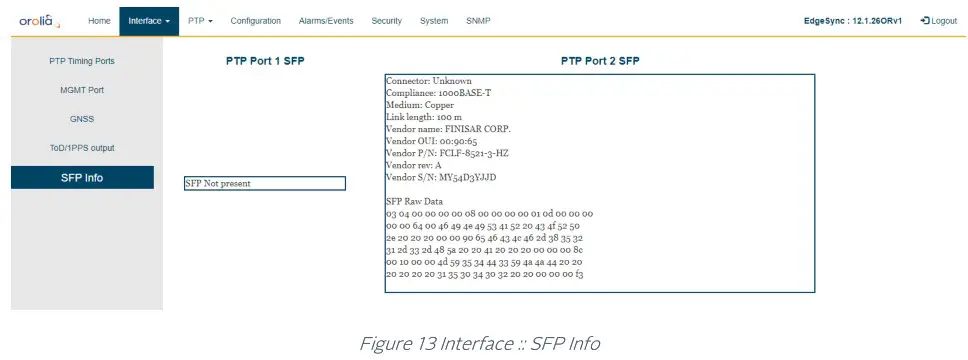
SFP Info
SFP Information page displays PTP ports optical module transceiver details as provided by the module vendor. Note that depending on specific SFP or vendor, some or all information may not be displayed.
PTP Webpage Tab
PTP Dropdown selections
- Config
- Clock
- Port
- Unicast
- Unicast Nodes
- Time
- SNTP
PTP:: Config
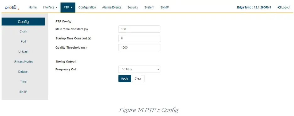
The Config webpage contains the following selections, entries, and buttons:
PTP:: Config | ||
| Labels | Access | Description |
| PTP Config | ||
| Main Time Constant(s) | RW | The main Time Constant used for the PTP servo after the servo has synchronized Range: 1 to 2147483647 |
| Startup Time Constant(s) | RW | The startup Time Constant used for the PTP servo before the servo has synchronized. Range: 1 to 2147483647 |
| Quality Threshold(ns) | RW | Maximum variation allowed in the sync and delay request direction, respectively, before packets are ignored. |
| Timing Output | ||
| Frequency Out | RW | Select Timing Frequency Output: 1544 kHz, 2048 kHz, and 10 MHz. |
| Apply / Clear | ||
| Apply Button | WO | Click for selection and settings to be applied to the EdgeSync |
| Clear Button | WO | Click to clear the latest changes |
Table 7 PTP Configuration Options
A description of the selections and settings for each entry on the PTP::Config web page is presented in the PTP (Slave) Servo Configuration Parameters Section of this User Guide.
PTP :: Clock
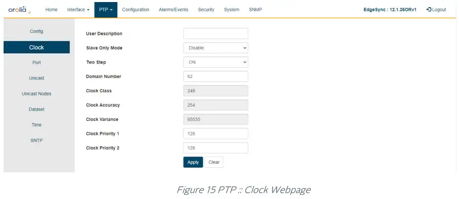
The Clock Webpage contains the following selections, entries, and buttons:
PTP:: Clock | ||
| Labels | Access | Description |
| Clock | ||
| User Description | RW | Optionally the user can provide a user description to identify this EdgeSync’s clock. Normal ASCII characters can be used -letters, numbers, and special characters. Note, the following characters are not allowed: ; (semi-colon), (space), and $. |
| Clock Type Mode | RW | Selection of PTP clock for this EdgeSync device. The options are: Ordinary Clock, Boundary Clock |
| Slave Only Mode | RW | Disable/Enable control for PTP Slave-only mode. In this mode, the PTP ports will always remain in Slave or Listening mode. |
| Two Step | RW | ON/OFF control of PTP two-step mode. |
| Clock Class | RW | PTP Clock class |
| Clock Accuracy | RW | PTP Clock accuracy |
| Clock Variance | RW | PTP Clock variance |
| Clock Priority 1 | RW | PTP Clock priority 1 |
| Clock Priority 2 | RW | PTP Clock priority 2 |
| Domain Number | RW | Configure the PTP Clock domain number |
| Apply / Clear | ||
| Apply Button | WO | Click for selection and settings to be applied to the EdgeSync |
| Clear Button | WO | Click to clear the latest changes |
Table 8 PTP Clock Options
There are additional PTP profile-specific parameters and options that will be selectively shown. More information is provided in the section describing PTP profiles.
PTP:: Port
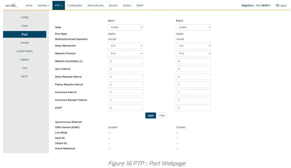
The Port Webpage contains the following displays, selections, entries, and buttons for Ports 1 and 2:
| PTP:: Port Legend: RO = Read Only, RW = Read/Write, WO = Write Only | ||||||||||||||||||||
| Labels | Access | Description | ||||||||||||||||||
| Port 1 and Port 2 | ||||||||||||||||||||
| State | RW | Select PTP port operational state: Disable / Enable | ||||||||||||||||||
| Port State | RO | PTP port state. The Clock Engine maintains the following states, and the port can be in one of these states. The statesare {Undefined, Initializing, Faulty, Disabled, Listening, Pre Master, Master, Passive, Uncalibrated, Slave} | ||||||||||||||||||
| L2 Multicast DA | RW | G8275.1 L2 multicast DA for PTP messages selection options: Forwardable, Non-forwardable, Forwardable only, and Non-forwardable only The table show more details for each of these options:
| ||||||||||||||||||
| Multicast/Unicast Operation | RO | PTP port operational mode status – Unicast or Multicast |
| Delay Mechanism | RW | Configuration of PTP delay mechanism: End-to-End (E2E) or Peer-to-Peer (P2P) |
| Network Protocol | RW | Configure PTP’s underlying network protocol. The options are: IPv4 (PTP over UDP/IPv4), IPv6 (PTP over UDP(6)/IPv6), ETH (PTP over L2 Ethernet) |
| Network Asymmetry (s) | RW | Configure Network Asymmetry delay to compensate for difference between the forward and return paths from this PTP slave port to PTP master as it may not be same or symmetric. The units are in seconds and can be configured as decimal. For e.g., to configure +1 usec asymmetry, this field should be set to 0.000001 seconds. |
| Sync Interval | RW | Configure the PTP Sync packet interval. The unit is in log to the base 2. For example, value = -5 is 32 packets/second, or value = 0 is 1 packet /second, or value = 2 is 1 packet in 4 seconds The range is -8 to +2 |
| Delay Request Interval | RW | Configure PTP Delay Request interval. The unit is in log to the base 2. For example, value = -5 is 32 packets/second, or value = 0 is 1 packet /second, or value = 2 is 1 packet in 4 seconds Range is -7 to +7 |
| Pdelay Request Interval | RW | Configure PTP Peer Delay Request Interval. The unit is in log to the base 2. For example, value = -5 is 32 packets/second, or value = 0 is 1 packet /second, or value = 2 is 1 packet in 4 seconds The range is -7 to +7 |
| Announce Interval | RW | Configure PTP Announce Interval. The unit is in log to the base 2. For example, value = -4 is 16 packets/second, or value = 0 is 1 packet /second, or value = 2 is 1 packet in 4 seconds The range is -4 to +5 |
| Announce Receipt Timeout | RW | Configure Announce Receipt Timeout in seconds. The range is +2 to +10 |
| DSCP | RW | Differentiated Service Code Point (DSCP) settings for PTP frames for network-wise QoS treatment |
| Apply / Clear | ||
| Apply Button | WO | Click for selection and settings to be applied to the EdgeSync |
| Clear Button | WO | Click to clear the latest changes |
| Synchronous Ethernet | ||
| SSM Channel (ESMC) | RO | ESMC channel is enabled or disabled |
| Link Mode | RO | IEEE 802.3 link mode: Master or Slave or none |
| Input QL | RO | Input QL on Rx ESMC message on this port |
| Output QL | RO | Output QL on Tx ESMC message on this port |
| Active Reference | RO | Following an active reference clock (frequency) |
Table 9 PTP Port Options
Note: The above configurations are per PTP port.
PTP:: Unicast
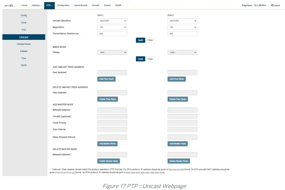
The Unicast Settings Webpage for Port 1 / Port 2 contains the following displays, selections, entries, and buttons:
| PTP :: Unicast Legend: RO = Read Only, RW = Read/Write, WO = Write Only | ||
| Labels | Access | Description |
| Port 1 and Port 2 | ||
| Unicast Operation | RW | Control of Unicast operation. The options are: DISABLED, MASTER, SLAVE, BOTH, MIXED |
| Negotiation | RW | Control for unicast negotiation, ON / OFF |
| Transmission Duration (s) | RW | Unicast transmission duration The range is 60 – 3600 seconds |
| Apply / Clear | ||
| Apply Button | WO | Click for selection and settings to be applied to the EdgeSync |
| Clear Button | WO | Click to clear the latest changes |
| MIXED Mode | ||
| PDelay | RW | Auto: pDelay responses will be multicast or unicast depending on pDelayReq Unicast: pDelay request and responses are always unicast |
| Peer Address | RW | Unicast peer address to use for peer delay mechanism |
| Delete Unicast Peer Address | ||
| Peer Address | RW | Remove Unicast peer address to add a different one |
| Add Master Node | ||
| Network Address | WO | IPv4 address of Master node to be added, four dot separate octets (0- 255) or Ethernet address, six dash separated double hexadecimal numbers (NN-NN-NN-NN-NN-NN) |
| ClockID [optional] | WO | Master Clock ID – optional field. Enter eight colon separated double hexadecimal numbers (NN:NN:NN: NN:NN:NN:NN:NN). |
| Clock Priority | WO | Clock priority Range is 0 – 255 |
| Sync Interval | WO | Configure the PTP Sync packet interval. The unit is in log to the base 2. For example, value = -5 is 32 packets/second, or value = 0 is 1 packet /second, or value = 2 is 1 packet in 4 seconds The range is -8 to +2 |
| Delay Request Interval | WO | Configure PTP Delay Request interval. The unit is in log to the base 2. For example, value = -5 is 32 packets/second, or value = 0 is 1 packet /second, or value = 2 is 1 packet in 4 seconds Range is -7 to +7 |
| Add Master Node Button | WO | Click for selection and settings to be applied to the EdgeSync |
| Delete Master Node | ||
| Network Address | WO | IPv4 address of Master node to be deleted, four dot separate octets (0- 255) or Ethernet address, six dash separated double hexadecimal numbers (NN-NN-NN-NN-NN-NN) |
| Delete Master Node Button | WO | Click for selection and settings to be applied to the EdgeSync |
Table 10 PTP Unicast Options
Note: The Sync Interval and Delay Request Interval are expressed in exponents of 2, with the Webpage entries being converted to intervals between messages in seconds or fractions of seconds.
Examples:
- an entry of 0 represents an interval of 1 second between messages
- an entry of -5 represents an interval of 1/32 seconds between messages or 32 messages per second.
PTP:: Unicast Nodes
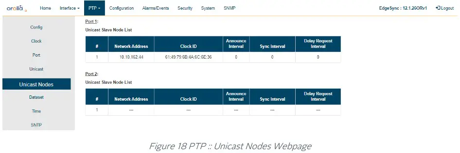
The Unicast Nodes Webpage contains the following selections, entries, and buttons:
| PTP:: Unicast Nodes Legend: RO = Read Only, RW = Read/Write, WO = Write Only | ||
| Labels | Access | Description |
| Port 1 and Port 2 | ||
| Unicast Master Node List | RO | Display Master Node List in a table format with the following information: Table Entry Number, Network Address, Clock ID, Priority, Sync Interval, Delay Request Interval, Announce granted state, Sync granted state, Delay response granted state. |
| Unicast Slave Node List | RO | Display Slave Node List in a table format with the following information: Table Entry Number, Network Address, Clock ID, Announce Interval, Sync Interval, Delay Request Interval |
Table 11 PTP Unicast Node Options
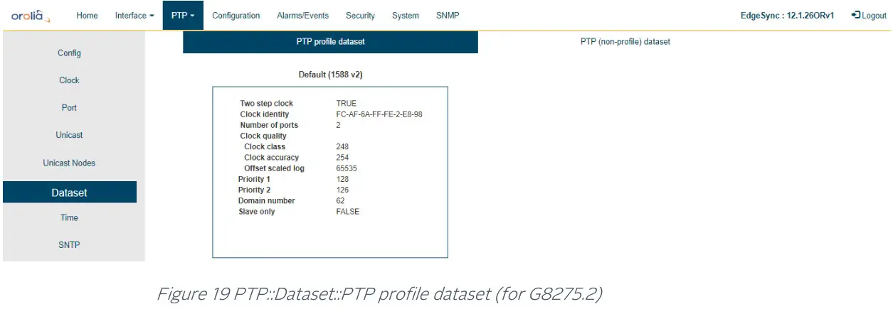
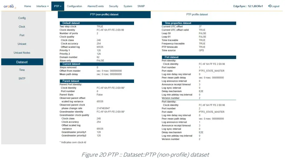
PTP:: Dataset
There are two sub-tabs on this webpage:
- PTP profile dataset
This tab provides profile specific information as shown below (G8275.2 profile, for example).
This information will be different based on what PTP profile has been chosen.
- PTP (non-profile) dataset

PTP:: Time
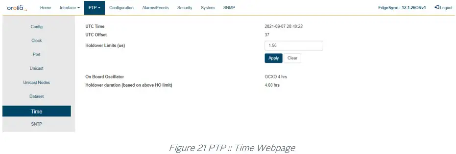
The Time Webpage for setting UTC time values contains the following displays, entries, and buttons:
| PTP:: Time Legend: RO = Read Only, RW = Read/Write, WO = Write Only | ||
| Labels | Access | Description |
| Time | ||
| UTC Time | RO | Display UTC time in the following format. YYYY-MM-DD HH:MM:SS |
| UTC Offset | RO | UTC offset in seconds. |
| Holdover Limits (us) | RW | Set the holdover limits. This time limit is used to determine the Holdover Duration Spec Achieved. The time limit value is the EdgeSync user’s maximum allowed error above the Quality Threshold setting on the PTP :: Config web page for the EdgeSync to remain in Holdover. |
| Apply / Clear | ||
| Apply Button | WO | Click for selection and settings to be applied to the EdgeSync |
| Clear Button | WO | Click to clear the latest changes |
| On-board Oscillator | ||
| On Board Oscillator | RO | Display OCXO and specified holdover duration |
| Holdover Duration Specs Achieved with Current XO and Holdover Limit Settings | RO | Display holdover duration based on the Holdover Limits (us) setting |
Table 12 PTP Time Options
PTP:: SNTP
The SNTP webpage is for setting up a Simple Network Time Protocol version 4 server. SNTP is a subset of Network Time Protocol used to synchronize computer systems in the network. SNTP synchronizes clients time with the server, that has already been synchronized by a source such as a from GNSS, PTP master or manually set, using date command using connectionless User Datagram Protocol in IP networks. This requires that there be an IP address configured on both PTP ports before enabling SNTP.
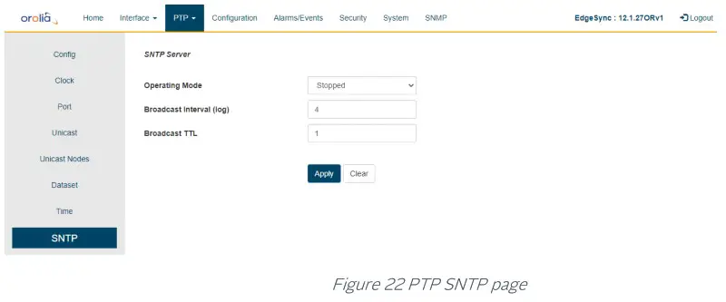
Enabling SNTP will make it operational on both PTP ports. The SNTP Webpage for setting server contains the following displays, entries, and buttons:
| PTP:: SNTP Legend: RO = Read Only, RW = Read/Write, WO = Write Only | ||
| Labels | Access | Description |
| Time | ||
| Operating Mode | RW | Stopped – To stop / disable SNTP server Unicast – To operate in unicast mode. Only IP unicast requests are answered Manycast – To operate in Manycast mode. IP unicast & multicast (224.0.1.1) requests are answered Broadcast – Periodic SNTP replies are broadcasted (224.0.1.1) Mixed – This is combination of Manycast and Broadcast |
| Broadcast Interval (log) | RW | Configure the Broadcast packet interval. The unit is in log to base 2. For example, value = 0 is 1 packet /second, or value = 3 is 1 packet in 8 seconds The range is 0 to 16 |
| Broadcast TTL | RW | Configure ttl value in broadcast packets. By default the value is set to 1. The range is 1 to 255 |
| Apply / Clear | ||
| Apply Button | WO | Click for selection and settings to be applied to the EdgeSync |
| Clear Button | WO | Click to clear the latest changes |
Table 13 SNTP Options
Configuration Webpage Tab
Configuration Tab supports the following:
- Restore Default Configuration
- Download Configuration
- Upload Configuration
The Configuration selections are described in the Configuration Webpage Tab Section of this User Guide.
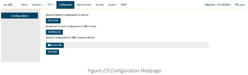
The Configuration Webpage for Restoring and Downloading the EdgeSync operational configuration contains the following displays, entries, and buttons:
| Configuration Legend: RO = Read Only, RW = Read/Write, WO = Write Only | ||
| Labels | Access | Description |
| Restore Default Configuration on Device | ||
| RESTORE button | WO | Click to restore EdgeSync Factory Default configuration. |
| Download Current Configuration in XML Format | ||
| DOWNLOAD button | WO | Download current EdgeSync configuration into browser’s default download folder. Downloaded in XML format. |
| Upload Configuration in XML Format to Device | ||
| Choose file button | WO | Browser button to navigate through the Host PC where the browser is running to select previously saved EdgeSync file to upload. |
| UPLOAD button | WO | Click to start the upload configuration option |
Table 14 Configuration Options
Alarms/Events Tab
Alarms/Events Tab Provides hardware alarm states and an event log generated by the EdgeSync software.
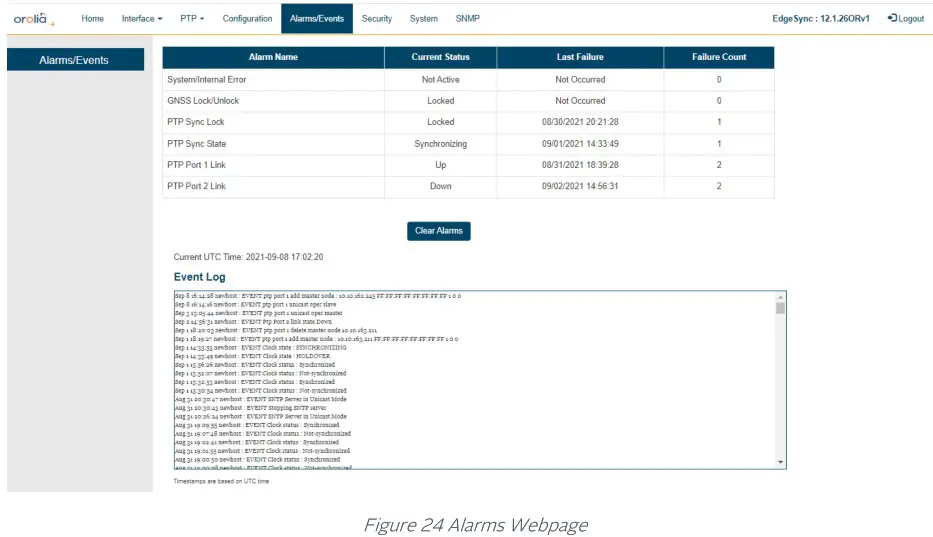
The Alarms section will list all the EdgeSync Alarms and their current status. The following is a list of the EdgeSync Alarms.
| Alarm | Detection Reason |
| System Internal Error | Any power or hardware component error detected |
| GNSS Lock/Unlock | When GNSS goes from Lock to Unlock state |
| PTP Sync Lock | When PTP engine goes from Lock to Unlock state |
| PTP Sync State | When PTP engine state goes out of Synchronizing |
| PTP Port 1 Link | Link goes from UP to DOWN |
| PTP Port 2 Link | Link goes from UP to DOWN |
Table 15 Alarm Detection Reason
Each Alarm entry will have the Alarm’s Name, the Alarm’s Current Status, the Alarm’s Last Occurrence and the number of times the Alarm has occurred since EdgeSync startup. The timestamp of last occurrence is UTC time.
The Clear Alarms button will clear Alarms that are no longer in a fault state, and the “Last Cleared At” time (in UTC) will be displayed on the page.
The Events section will display the event Log that is maintained by EdgeSync software. The information it maintains include operations like configuration changes, reboot, software upgrade, as well as any asynchronous events detected from hardware or operation like link loss, synchronization status change, etc. For each event, a timestamp is also shown. The timestamps in the log are based on the EdgeSync generated UTC time.
Security Tab
Security Tab Currently, this page provides control for https secure way of accessing EdgeSync over the web. The web access or GUI for EdgeSync is over http protocol which can be either:
non-secure (http): Mainly for inside customers’ secure or internal network does not need SSL certificate secure (https): For improved security, or in public network encrypted with or without a proper Secure Sockets Layer (SSL) certificate issued or signed from a public certified authority (CA) for authentication against man-in-the-middle or similar security risks.
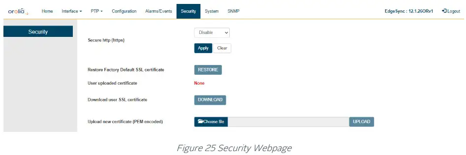
| Security Legend: RO = Read Only,,Bsiligga/Write, WO = Write Only | ||
| Labels | Access | Description |
| Security | ||
| Secure http (https) | RW | Enable/Disable HTTPS |
| Apply / Clear | ||
| Apply Button | WO | Click for selection and settings to be applied to the EdgeSync |
| Clear Button | WO | Click to clear the latest changes |
| Restore Factory Default SSL certificate | WO | Restore Orolia’s self-signed SSL certificate |
| User-uploaded certificate | RO | File name of the user-specific SSL certificate (PEM format) |
| Downloaded user SSL certificate | RO | Download user-specific SSL certificate that was uploaded previously |
| Upload new certificate (PEM encoded) | WO | Upload a user-specific SSL certificate. This may be a proper public certificate signed by a valid Certificate Authority (CA) |
Table 16 Security Options
Without proper authentication, the client or browser accessing EdgeSync may warn the user that the access is “not secure” since the SSL certificate has not been authenticated. With https, all web transactions are encrypted regardless of SSL certificate is authenticated or not.
NOTE: If an incorrect file or wrongly formatted user SSL certificate is uploaded and the web access to EdgeSync stops working, then the user can restore to factory default https configuration from CLI using the “HTTPS Restore” command.
System Tab
System Tab Provides EdgeSync hardware and software information like version, Oscillator type, GNSS Receiver type, and entries, upgrade, and logs.
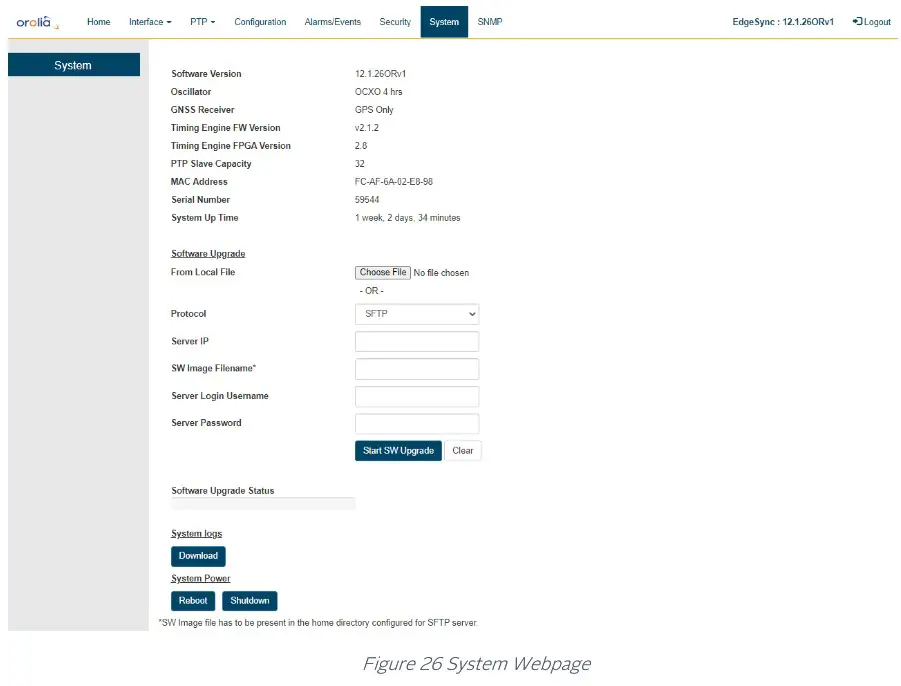
The System Webpage for EdgeSync system and firmware information contains the following displays, entries, and buttons:
| System Legend: RO = Read Only, RW = Read/Write, WO = Write Only | ||
| Labels | Access | Description |
| System | ||
| Software Version | RO | Version of EdgeSync software |
| Oscillator | RO | OCXO 4 hours or OCXO 8 hours |
| GNSS Receiver | RO | GNSS Receiver information |
| Timing Engine FW Version | RO | Version of firmware that is running on the Orolia’s internal Managed Clock Engine |
| Timing Engine FPGA Version | RO | Version of FPGA that is running on the Orolia’s internal Managed Clock Engine |
| MAC Address | RO | MAC address of port 1 |
| Serial Number | RO | Serial number |
| System Up Time | RO | Time since last reboot |
| Software Upgrade | ||
| From Local File button | RW | Browser button to navigate through the Host PC where the browser is running to select previously downloaded EdgeSync software |
| Protocol pull-down option | RW | Only SFTP option is supported. Note, the image file is expected to be in the home directory on SFTP server |
| Server IP | RW | IPv4 address of SFTP server |
| SW Image Filename | RW | Software file to be used for the upgrade |
| Server Login Username | RW | Login credentials for SFTP server |
| Server Password | RW | Login credentials for SFTP server |
| Start SW Upgrade button | WO | Clicking the button initiates upgrade process |
| Clear button | WO | Click to clear the latest changes |
| Software Upgrade Status | RO | Display bar to show the upgrade progress |
| System Logs | ||
| Download | WO | Download the EdgeSync MCE Event Log to the Host PC. The log file is encrypted and is for Orolia use. |
| System Power | ||
| Reboot button | WO | Reboot the EdgeSync system |
| Shutdown button | WO | Shutdown of the EdgeSync in controlled and sequential steps that will protect the EdgeSync memory storage. Using this button is recommended prior to disconnecting physical power to the EdgeSync. |
Table 17 System Options
IMPORTANT NOTE ON SOFTWARE UPGRADE:
Stopping the Engine is recommended before doing the software upgrade
SNMP Tab
SNMP Tab Provides SNMP (v2, v3) Management Server configuration.
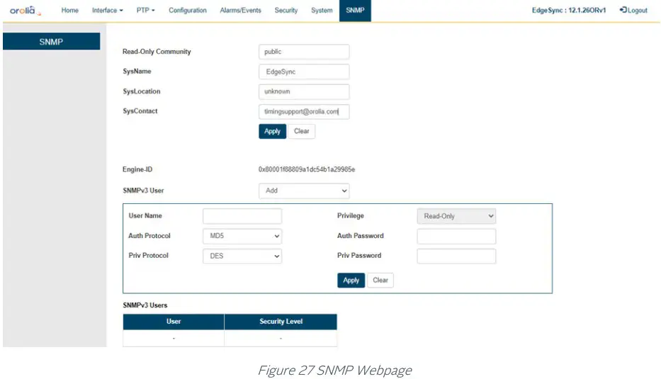
The SNMP Webpage for the SNMP configuration contains the following entries, and buttons:
| SNMPv2 Legend: RO = Read Only, RW = Read/Write, WO = Write Only | ||
| Labels | Access | Description |
| SNMPv2 | ||
| Read-Only Community | RW | Community string — usually ‘public’ or ‘private’ |
| SysName | RW | Administratively assigned name for this EdgeSync node in the network |
| SysLocation | RW | Location of this EdgeSync node |
| SysContact | RW | Contact information for support for this EdgeSync node |
| Apply / Clear | ||
| Apply Button | WO | Click for selection and settings to be applied to the EdgeSync |
| Clear Button | WO | Click to clear the latest changes |
Table 18 SNMPv2 Options
EdgeSync supports SNMP v3 as well and the table below shows the related parameters.
| SNMPv3 Legend: RO = Read Only, RW = Read/Write, WO = Write Only | ||
| Labels | Access | Description |
| SNMPv3 | ||
| Engine-Id | RO | Unique Engine-Id specific to a EdgeSync unit |
| SNMP v3 user | RW | Add/Delete SNMP users |
| User Name | RW | User name to be added (or deleted) |
| Privilege | RO | Read-Only (as specified in PTPMIB) |
| Auth Protocol | RW | Selection of authorization protocol: MD5 or SHA (applicable only when adding a new user) |
| Auth Password | WO | Authorization password – should be at least 8 characters (applicable only when adding a new user) |
| Priv Protocol | RW | Selection of privacy protocol: MD5 or SHA (applicable only when adding a new user) |
| Priv Password | WO | Privacy password – should be at least 8 characters (applicable only when adding a new user) |
| Apply / Clear | ||
| Apply Button | WO | Click for selection and settings to be applied to the EdgeSync |
| Clear Button | WO | Click to clear the latest changes |
Table 19 SNMPv3 Options
EdgeSync maintains the list of active SNMPv3 users with the user name and their security level at the bottom of the webpage.
Command Reference
EdgeSync Basic Commands
The login credentials for accessing EdgeSync CLI shell is admin/admin. This is a list of the available commands related to the control and monitoring of the EdgeSync. The CLI commands are case insensitive.
Help Command
help – After logging in, the user can enter “help” to get a list of commands and descriptions to be displayed on the command terminal.
History Command
history – To view the history of previously entered commands, enter “history”.
Quit Command
quit – To terminate the command session and log out, enter “quit”. Note that, pressing Control-C will have the same effect as “quit” command.
Show commands
The “show” command can be used to show alarms or clock status.
Show Alarms Command
show alarms – This command will display any active EdgeSync alarms. If no alarms are present, the Alarm Name and State columns will be blank.
Show Status Command
show status – This command shows the Managed Clock Engine’s Sync information EdgeSync Sync Status and EdgeSync Sync State.
- EdgeSync Sync Status can be either LOCKED or UNLOCKED.
- EdgeSync Sync State can be one of the following: FREE RUNNING, SYNTONIZING, SYNCHRONIZING, or HOLDOVER.
- GNSS 1PPS Status can be either Stable or Unstable.
- GNSS ToD Status can be either Stable or Unstable.
System commands
These are system-level commands.
System Info Command
system info -The System Info command displays the basic system information EdgeSync firmware version, on-board oscillator type, Managed Clock Engine Firmware version, number of PTP slaves supported and GNSS module type.
System Restore Command
system restore – The EdgeSync System Restore command will restore factory default configuration.
System Upgrade Status Command
system Upgrade_Status – The EdgeSync System Firmware Upgrade Status will be displayed if the upgrade was initiated previously from either CLI or through Web User Interface.
System Upgrade Start Command
system Upgrade_Start – The EdgeSync System Upgrade Start command will perform firmware upgrade when the following inputs are provided:
- File transfer protocol, 1 or 2 (for FTP or SFTP).
Note: Option 1 (FTP) has been deprecated and is not available anymore - Hostname, as either IP address or DNS name
- File name containing the upgrade FW
Network Commands
The Network Command operate on the Management port. The user can set up the network parameters like enable/disable DHCP, static IPv4 address, netmask, and gateway addresses and display the current setting of it. By factory default, the Management port network parameters are set statically as follows:
- DHCP: Disabled
- IP Address: 192.168.2.100
- Netmask: 255.255.255.0
- Gateway: 0.0.0.0
Network Configure Command
network config – This command lets the user configure EdgeSync Management port network parameters.
Network Status Command
network status – Get network status for the Management Port, PTP Timing Port-1, and PTP Timing Port-2.
Network Ping Command
network ping – Send a ping message to a device on the network to test reachability. The results of the ping operation are displayed as “Ping Success” or “Ping Failed”.
The ping command takes an additional parameter “mgmt” or “ptp” to specify from which port the ping request needs to go out.
HTTPS Restore command
HTTPS restore – This command is provided in case of user uploading an incorrect file or wrongly formatted SSL certificate (PEM format) file via the EdgeSync GUI. Executing this command gives the user to option to reset to factory default removing the user uploaded SSL certificate file and restoring the self-signed certificate. This is needed if wrong user file got uploaded and user is unable to access EdgeSync from their browser.
Date command
date – This command is provided mainly for initial customer lab bring-up or for those deployments where there is no timing reference (like GNSS) but need EdgeSync to act as a Grandmaster to propagate time and synchronization over PTP to slave units. This command enables the user to set the date and time (ToD) on EdgeSync manually. The user can enter the wall-clock time for the present date and time with this command with the “set” option. The date command without any parameters will display the current ToD.
NOTE: If there is a proper timing reference available (like GNSS time or a remote PTP master), then the time set by this command will be overwritten by the actual ToD received from the timing reference. This command is not needed for normal operation with a good timing reference.
Reboot command
reboot – The Reboot command is to provide for user initiated manual reboot of EdgeSync system. Note that a firmware upgrade will automatically initiate reboot of the system.
Monitoring Log command
monitoring log – This command will start a log of the Managed Clock Engine’s Sync information in PTP only and PTP primary and GNSS secondary mode. The data points are: EdgeSync Sync Status, EdgeSync Sync State, Steps removed, Offset from master (in ns), Mean path delay (in ns) and the timestamp.
The log will be printed out on the console every 10 to 13 seconds. To stop the log, the user will have to press “Ctrl + c”. Once “Ctrl + c” is pressed the console will print “Stopping the monitoring log” and a new command line will appear.
- EdgeSync Sync Status can be either LOCKED or UNLOCKED.
- EdgeSync Sync State can be one of the following: FREE RUNNING, SYNTONIZING, SYNCHRONIZING, or HOLDOVER.
Troubleshooting and Safety Considerations
This section provides some EdgeSync Troubleshooting and Safety Considerations. References are provided on how to get technical or sales assistance and how to obtain manual updates.
Troubleshooting
This section provides some EdgeSync Troubleshooting practices and the indicators for when a problem may be present in the EdgeSync operation. Some of the indicators of EdgeSync problems are Front Panel LED states, Interface and PTP Webpage statuses and the Alarms/Events Tab Webpage.
| Symptom | Probable Cause | Recommended Action |
| Power LED is Red | User Interface and Control Plane Processor has not completed its boot up process. | Wait for a few seconds for it to turn orange and then finally green when all of software has been brought up. It takes approximately 4 minutes for the LED to turn green when system is ready for operation. |
| Power supply does not meet EdgeSync requirements. | Verify that the voltage from the EdgeSync power source meets the specifications of the Power Section. | |
| EdgeSync Alarm condition is affecting power. | Check the Alarms/Events Tab Webpage for information about any EdgeSync alarms that might affect power. | |
| GNSS LED is Off | EdgeSync has not completed its boot up process. | Wait approximately 4 minutes for software to complete booting. |
| MCE running in PTP Only mode. | None. The LED is off when MCE is in PTP Only mode. | |
| GNSS LED is Red | 1 PPS Input Error on Front Panel RJ45 port | Verify that the input RJ45 connector is securely inserted in the port. Verify that the 1 PPS source is outputting a 1 PPS signal. |
| ToD Input Error on Front Panel RJ45 port | Verify that the input RJ45 connector is securely insertedin the port. Verity that the ToD source is outputting a ToD signal. | |
| GNSS input signal from Antenna and cable is missing or weak. | Verify that the GNSS Antenna coax is securely plugged into the SMA port. Verity that the GNSS Antenna signal is present. | |
| EdgeSync Alarm condition is affecting 1 PPS or ToD Input. | Check the Alarms/Events Tab Webpage for information about any EdgeSync alarms that might affect 1 PPS or ToD Input. | |
| Sync Status LED is Off | MCE Processor has not completed its boot up process. | Wait approximately 4 minutes for the MCE processor to complete booting. |
| Sync Status LED is Red | MCE is operating in GNSS Only mode and is not receiving the GNSS inputs. | Verify that the GNSS LED is Green. |
| MCE is operating in PTP Only mode and is not receiving PTP Grand Master timing messages. | Verify that the PTP Port 1 or Port 2 is connected to a PTP Grand Master time source through the RJ45 or SFP connectors. Verify that the PTP Grand Master is providing PTP Timing messages. | |
| MCE is operating in GNSS Primary / PTP Secondary mode, or in PTP Primary / GNSS Secondary mode and is not receiving timing signals from either source. | Verify that the GNSS LED is Green. Verify that the PTP Port 1 or Port 2 is connected to a PTP Grand Master time source through the RJ45 or SFP connectors. Verify that the PTP Grand Master is providing PTP Timing messages. | |
| The user has selected external 1PPS / ToD inputs but has not connected the input sources. | On the EdgeSync Front Panel, connect the 1PPS / ToD RJ45 input source. On the Interface :: GNSS web page, Enable 1PPS In and ToD In. | |
| EdgeSync Alarm condition is affecting inputs from the GNSSor the PTP Grand Master. | Check the Alarms/Events Tab Webpage for information about any EdgeSync alarms that might affect timing input signals. | |
| Sync Status LED is Amber | MCE is operating in GNSS Only mode and is not synchronized to the GNSS input. | Verify that the GNSS LED is Green. |
| MCE is operating in PTP Only mode and is not synchronized to the PTP Grand Master. | Verify that the PTP Port 1 or Port 2 is connected to a PTP Grand Master time source through the RJ45 or SFP connectors. | |
| Verify that the PTP Grand Master is providing PTP Timing messages | ||
| MCE synchronization loop control system has not converged to the input timing source. | Wait 2 to 15 minutes for the MCE to converge and synchronize to the input timing source. | |
| EdgeSync Alarm condition is affecting MCE synchronization. | Check the Alarms/Events Tab Webpage for information about any EdgeSync alarms that might affect MCE synchronization. | |
| Home Webpage – GNSS 1 PPS Status Unstable/Unavailable | GNSS input signal from Antenna and cable is missing or weak. | Verify that the GNSS Antenna coax is securely plugged into the SMA port. Verify that the GNSS Antenna signal is present. |
| GNSS Antenna / cable configuration does not meet requirements of the Antenna input Section. | Verify that the GNSS Antenna / cable meets requirements of the Antenna input Section. | |
| EdgeSync Alarm condition is affecting inputs from the GNSS | Check the Alarms/Events Tab Webpage for information about any EdgeSync alarms that might affect GNSS input signals. | |
| Home Webpage – GNSS ToD Status Unstable/Unavailable | GNSS input signal from Antenna and cable is missing or weak. | Wait approximately 2 minutes for the MCE processor to complete booting. |
| GNSS Antenna / cable configuration does not meetrequirements of the Antennainput Section. | Verify that the GNSS Antenna / cable meets requirements of the Antenna input Section. | |
| The user has selected external 1PPS / ToD inputs but has not connected the input sources. | On the EdgeSync Front Panel, connect the 1PPS / ToD RJ45 input source. On the Interface :: GNSS web page, Enable 1PPS In and ToD In. | |
| EdgeSync Alarm condition is affecting inputs from the GNSS. | Check the Alarms/Events Tab Webpage for information about any EdgeSync alarms that might affect GNSS input signals. | |
| Interface :: PTP Timing Ports Webpage – Link State not up | PTP Timing Port 1 or Port 2 IP address configuration is incorrect. | Verify that IP configuration for Port 1 and Port 2 is correct on the Interface :: PTP Timing Ports Webpage. Verify that the network routers/switches/hubs between the EdgeSync Port 1 and Port 2 and the timing network are properly connected. |
| Port 1 and Port 2 are in the same network / subnet as the MGMT port. | Make sure that the IP addresses of Port 1, Port 2 and MGMT port are on different networks/subnets. | |
| EdgeSync Alarm condition is affecting Timing Ports Link State. | Check the Alarms/Events Tab Webpage for information about any EdgeSync alarms that might affect Timing Ports Link State. | |
| Interface::MGMT Port Webpage – Link State not up | MGMT Port IP address configuration is incorrect. | Verify that IP configuration for MGMT Port is correct on the Interface:: MGMT Port Webpage. Verify that the network routers/switches/hubs between the EdgeSync MGMT Port and the management network are properly connected. |
| MGMT Port is on the same network/subnet as the timing ports. | Make sure that the IP address of the MGMT port and the addresses of Port 1 and Port 2 are on different networks/subnets. | |
| EdgeSync Alarm condition is affecting MGMT Port Link State. | Check the Alarms/Events Tab Webpage for information about any EdgeSync alarms that might affect MGMT Port Link State. |
Safety Considerations
The following safety consideration should be used when handling and installing the EdgeSync.
- When installing or working on the EdgeSync equipment, ESD wrist straps should be worn.
- Use the specified power supply and ground for the EdgeSync equipment as stated in the Power and Ground Connections section.
- Refer to the Applying Power section when applying power to the EdgeSync equipment.
- When rack mounting the EdgeSync equipment, use the original mounting screws provided with the mounting bracket so that the EdgeSync case will not be damaged. Do not substitute other mounting screws.
- Only authorized personnel should open the EdgeSync equipment enclosure. Unauthorized access to the EdgeSync equipment could result in equipment damage and voiding the EdgeSync warranty.
- Use caution when installing the GNSS antenna near, under, or around high voltage lines. The GNSS antenna should be equipped with proper external lightning protection/grounding to avoid equipment damage should the antenna receive a lightning strike.
- If the EdgeSync is rack mounted, 1RU above the EdgeSync enclosure must be left unoccupied for heat dissipation.
Managed Clock Engine Overview
EdgeSync Engine Modes
The EdgeSync Managed Clock Engine can operate in four different modes. The operational mode defines the functionality supported by the engine, EdgeSync clock behavior and its properties in different operating conditions. The operational mode is specified upon startup and can only be changed by restarting the engine on the Home Webpage.
- PTP Only
- GNSS Only
- GNSS Primary, PTP Secondary
- PTP Primary, GNSS Secondary.
In addition to these four modes, a Slave Only mode is supported. The clock can be switched to the Slave Only mode and back at any time and from any of above operational modes. The Slave Only mode is selected on the PTP:: Clock Webpage.
PTP Only mode
This is an ordinary PTP master-slave mode. The GNSS interface is disabled. In this mode, the clock normally acts as a PTP slave, but may also become a PTP master if no better clock exists on the network based on the Best Master Clock Algorithm (BMCA).
The clock class is initialized to value of DEFAULT (248).
GNSS Only mode
In this mode, the clock is a GNSS-clock and the GNSS is the only source of synchronization. The clock can never become a slave to another clock regardless of its clock class.
In this mode, the clock class is automatically controlled by the engine. The clock is initialized with class of DEFAULT (248), and when it locks to a stable GNSS signal it raises the class to PRC_SYNC (6) or APP_SYNC (13). If only the 1PPS-input signal is available, then the class APP_SYNC (13) is selected. If the ToD-input signal is available as well, then the timescale is automatically switched to PTP and the clock class is PRC_SYNC (6).
Later, if the GNSS-signal is lost, the clock switches to the holdover mode and lowers its class to PRC_HOLDOVER (7) or APP_HOLDOVER (14). If after the holdover period, the GNSS-signal is still not available the clock downgrades its class PRC_DEGRADATION_A (52) or APP_DEGRADATION_A (58) and stays as the PTP master in the free running mode. If a better clock exists on the network based on BMCA, the clock will switch to the PTP passive state.
GNSS Primary, PTP Secondary mode
This mode is almost the same as the previous mode, Mode GNSS Only, but after the holdover duration the clock degrades its class to PRC_DEGRADATION_B (187) or APP_DEGRADATION_B (193), so clock can potentially become a PTP slave if a better clock appears on the network.
This mode means that the EdgeSync clock has the GNSS-signal as its primary source of synchronization and the PTP as a backup source, i.e. when no GNSS-signal present.
PTP Primary, GNSS Secondary Mode
This mode is designed for unstable GNSS-reception environments, where the node having a better signal reception becomes a PTP master and all others become PTP slaves, even if they have their own GNSS signal.
The clock is initialized with class DEFAULT (248) and the class is not changed by the engine while operating. Instead after detecting the stable GNSS signal the engine increases the priority2 member of the Default Dataset (lowers its value) by some small margin, which might depend on the reception quality. That clock which has a higher priority2 (better GNSS signal reception) becomes the PTP master on the network and all others synchronize with it.
GNSS Interface
The EdgeSync supports GNSS L1 input signals from a GNSS antenna. Signal frequency is 1575.42 MHz for GPS; 1561.098 MHz for Beidou; and 1602.0 MHz for Glonass. The status and configuration of GNSS interface can be accessed via the Interface:: GNSS Webpage.
EdgeSync Clock Sync States
EdgeSync clock at any instance of time can be in one of four following sync states:
- FREE RUNNING
- SYNTONIZING
- SYNCHRONIZING
- HOLDOVER
- UNKNOWN/ERROR
FREE RUNNING State
The EdgeSync clock comes into this state upon initialization. The EdgeSync clock time is not set, the clock class is DEFAULT (248), clock accuracy is UNKNOWN (0xFE).
The timescale is PTP, the UTC offset is initially set to 37 secs, leap flags are FALSE. In Free Running state, the clock frequency comes from the on-board oscillator.
SYNTONIZING State
This state is only possible when the 1PPS-input signal from the GNSS interface is available, but not the ToD-input signal and the clock become a PTP master.
When the EdgeSync engine is running in GNSS Only mode or PTP Only mode, the clock class is automatically changed to either PRC_SYNC (6) or APP_SYNC (13) and the clock accuracy is set to WITHIN_100_NS. In GNSS Primary, PTP Secondary mode, the clock class remains unchanged.
Note that the frequency can be traced, but not the time in this state. Once the ToD-input signal becomes available the clock switches to SYNCHRONIZING state.
SYNCHRONIZING State
The EdgeSync clock enters this state when it starts to synchronize its time and frequency with either a PTP or GNSS source. If the synchronization source is the GNSS, then both time and frequency are present and traceable. The timescale is changed to PTP, the clock class is changed to PRC_SYNC (6) and the clock accuracy is set to WITHIN_100_NS.
If the ToD-input signal becomes unavailable, while the 1PPS-input is still present, the EdgeSync clock switches to SYNTONIZED state.
If the synchronization source is a PTP master, then the clock quality remains unchanged. The timescale is set according to what is distributed by the PTP master. If the timescale distributed is PTP then the UTC offset (if valid) and leap flags are also set to master’s values and the time source is set to PTP.
HOLDOVER State
The EdgeSync clock enters this state when the synchronization source is lost. If the clock was synchronized with PTP master its clock class remains unchanged. Otherwise the clock class is modified according the engine’s operational mode and the clock accuracy is changed based on the time spent in the holdover state.
There is a static parameter which defines the clock stability. Currently it is fixed to 1 ns/s for a temperature-stable environment. During the holdover state an estimated error value is calculated and the clock accuracy is set according to that value.
The maximum time the clock stays in holdover state is defined by the holdover duration. By default, this value is set to 1000 seconds which gives about 1 microsecond error at the end of holdover duration. After the holdover duration, the clock switches to the FREE RUNNING state, and its accuracy is reset to UNKNOWN (0xFE).
UNKNOWN/ERROR State
The EdgeSync clock has entered a failed or error condition and the sync state is unknown.
Unicast Operations
By default, unicast operations are disabled and the EdgeSync port operates in multicast mode. After unicast mode is enabled no multicast communications are possible.
The PTP port can be switched to unicast operations and back at any time using the There are additional PTP profile-specific parameters and options that will be selectively shown. More information is provided in the section describing PTP profiles.
PTP:: Port and PTP :: Unicast Sections of this User Guide.
Unicast Master
A EdgeSync port in unicast master state can support:
- Slave nodes which dynamically request unicast message transmission services from the master using the unicast negotiation mechanism.
- Slave nodes which do not support the unicast negotiation and simply rely on the reception of unicast messages from the master.
To accept unicast negotiation requests from slave nodes the master needs to be configured as follows:
- Unicast negotiation must be enabled.
- Slave acceptance filter must be populated. Note that in the current design, the slave acceptance filter is not user-configurable, and it is set to accept all slaves.
To provide message transmission services to slave nodes which do not support the unicast negotiation the master needs to be manually configured with the list of static slave nodes.
Enabling Master Unicast Negotiation
The unicast negotiation state is controlled by the PTP :: Unicast Section of this User Guide.
When unicast negotiation is enabled the master accepts unicast transmission requests from negotiation-capable nodes. If a node is allowed by the acceptance filter and if enough resources are available, the master grants message transmission services to that node.
If unicast negotiation is disabled no new requests are accepted, but all existing grants remain serviced until they are either expired or cancelled.
Maintaining Master’s Slave Acceptance Filter
Note: In the current implementation, the slave acceptance filter is not user-configurable and it is set to accept all slaves. In that respect, the following documentation on slave acceptance filter is only for academic purpose.
The slave acceptance filter is a mechanism to control which slave nodes may obtain unicast services from the master. If the filter table is empty no services will be granted to any node. The PTP :: Unicast Section of this User Guide is used to manipulate the slave acceptance filter.
As the result of the filter table modification, if a node becomes unacceptable or message rates of any active grants becomes beyond the newly configured limits, all affected grants will be cancelled.
Maintaining Master’s List of Static Slaves
Note: In the current implementation, this is not supported. To provide unicast services to slaves which do not support the unicast negotiation the master maintains a list of static slave nodes.
When a node is in this list the master can send Announce and Sync messages to that node and can reply to Delay Request messages received from that node.
PTP:: Unicast Section of this User Guide is used to monitor and manipulate the static slave node list.
Unicast BOTH mode of operation
The PTP port on EdgeSync can be configured to automatically assume either the role of a unicast Master or a unicast Slave when the port mode is unicast BOTH. For example, if a port is in unicast Master mode and has GNSS reference and if the GNSS reference is lost, it can switch over to unicast Slave to another GM in the network. It is important to note that it is mutually exclusive, and cannot assume both, unicast Master and unicast Slave role at the same time as the case would be in a singlearmed boundary clock.
Unicast MIXED mode of operation
The MIXED mode of operation is also referred to as PTP hybrid mode. In this mode, the Announce and Sync messages are sent as a multicast, but the delay mechanism is in unicast mode. The advantage of doing so is two-fold in a network of single master and many slaves that are being serviced by that Master:
- The Master does not have to replicate the Announce and Sync (and Follow-up) messages for each slave in its time domain or in the network,
- Each slave does not have to receive, process and drop DelayReq and DelayResponse messages from other slaves in the network.
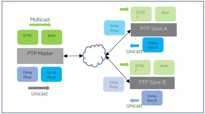
Figure 28 MIXED mode of operation
The delay mechanism can be end-to-end (E2E) as show in the figure or can be peer-to-peer(P2P). In P2P, typically the peer delay mechanism (i.e., sending a Peer Delay Request and getting a Peer Delay Mechanism) is typically over multicast. But, in the case of MIXED mode and with P2P delay mechanism enabled, then the peer unicast addresses may be used and need to be statically configured.
The MIXED mode of operation is used in the broadcast industry with SMPTE profile.
Monitoring Unicast Operations
Monitoring the status of master unicast operations can be done on the PTP :: Unicast Nodes and PTP :: Dataset Sections of this User Guide.
PTP Clocks
IEEE 1588 v2 standard specifies different types of clocks that are used to propagate timing and synchronization. The grandmaster, master and slave (or subordinate) clocks are generally grouped as ordinary clocks. Intermediate switches and routers in the network can either be a Transparent Clock (TC) or Boundary Clock (BC). BCs are preferable to TCs as they provide more accuracy and can easily scale in large networks. Using a hierarchical architecture and using divide and conquer principle, a single grandmaster does not have to serve large number of slaves.
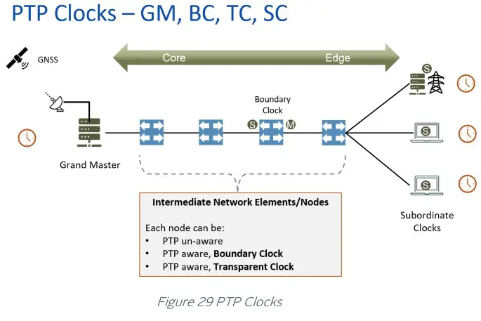
Gateway and Boundary clock
The EdgeSync Multi-Sync Gateway has the capability of using both of its Ethernet ports (Port 1 and Port 2) as PTP ports. This opens the possibility of using the EdgeSync as a two-port gateway or boundary clock. For more information about Gateway and Boundary Clocks, see [1].
The Gateway Clock
The Gateway Clock (GC) can be considered as an Ordinary Clock (OC) with two ports, with one port configured as a master and the other port configured as a slave.
Another capability of the EdgeSync is for both ports to be configured as master ports. In that configuration, each port would have its own IP address and be associated with different subnets. However, both ports would have the same PTP Clock Identity. With each port connected to different subnets, the ports can serve as GM for the slaves on the two different subnets. The slaves on the two separate subnets would then use the BMCA to select the best GM from which to recover the PTP time messages.
The Boundary Clock
The Boundary Clock (BC) has one port defined as a master port and the second port as a slave port receiving PTP messages from an external Grand Master (GM) Clock. The PTP Clock Webpage is used to set the EdgeSync clock as a boundary clock, described in PTP :: Clock Section of this User Guide.
The following figure illustrates the difference between a Gateway Clock and a Boundary Clock. The slaves connected to a Gateway Clock will only recognize the Gateway Clock as a Grand Master and not any other upstream masters. In the following figure, the slaves connected to the Gateway Clock will not recognize the Clock 1(GM). The slaves that are connected to the Boundary Clock will recognize Clock 1(GM) as the Grand Master.
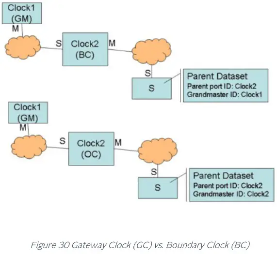
PTP (Slave) Servo Configuration Parameters
Main Time Constant
The main time constant used by the PTP Servo (slave) algorithm, in seconds. A longer time constant makes the oscillator frequency change more slowly and less responsive to changes in a network environment, such as the temperature or the network delays. For networks with low packet delay variation a short time constant (e.g., 30 sec) can be used. For networks with unknown or high traffic load, a longer time constant (e.g., 300 sec) would be a better setting. A longer time constant requires a more stable oscillator to be effective. For example, a time constant above 500 sec requires the EdgeSync+ HP OCXO. The default value is 100 sec.
Startup Time Constant
The time constant used during the period of obtaining a preliminary synchronization (startup phase), in seconds. If this field is set to 0 the main time constant will be used. This parameter can help to shorten the synchronization time when a long main time constant is required. But values that are too short may lead to unwanted oscillations which increase the total time required to synchronize and eliminate any positive effects of shorter startup time constant. The default value is 0.
Quality Threshold
Defines the maximum allowed time variation in nanoseconds before the slave goes into holdover. The time variation is based on a statistical measurement of time error between the source input time and the slave’s formulated time, where the source input time is the GNSS or ToD + 1PPS input. The default value is 1500 nsec.
Network Type
The Network Type selection is used to adjust the loop control algorithm behavior according to the underlying network characteristics. There are three types of networks currently supported: Unmanaged, Managed, and Full on-path.
“Unmanaged” selection is used for a network with unknown or unspecified packet delay and delay variation or with packet delay distribution that may dramatically change its characteristics over time.
“Managed” selection is used for a network where the packet delay and delay variation distribution are specified and that always has a distinct “floor”. That “floor” may vary over the time, but the distribution limitations provided by the “floor” should still be present.
“Full on-path” selection is used along with G.8275.1 profile, where all network elements in the network participate in PTP protocol.
Frequency Out
The syntonized frequency that will be output on the FREQ Out port on the EdgeSync Front Panel. The valid options are 10MHz (default), 1.54MHz (T1 frequency) and 2.048 (E1 frequency).
SNTP
Besides PTP timing protocol, EdgeSync supports SNTP (Simple Network Time Protocol) for those applications where very high precision (i.e., sub-microsecond accuracy) synchronization is not a requirement. Many client devices and their operating systems synchronize to a NTP server. EdgeSync can operate as a Stratum-1 NTP server to provide of this time. In this regard, Stratum-1 NTP server is the same as SNTP server. EdgeSync can operate as a PTP grandmaster or as a NTP Stratum-1 server, by getting time reference from GNSS and distributing that over the network to PTP slaves or NTP clients. If SNTP is enabled, then EdgeSync can service both, PTP slaves as well as NTP clients.
 SNTP server implementation of EdgeSync as per the specification in RFC 4330 – Simple Network Time Protocol (SNTP) Version 4 for IPv4, IPv6 and OSI.
Network Architecture, Deployment Considerations
Network Operator’s or Carrier’s perspective
The diagram below shows the carrier’s perspective of the network with a view of the synchronization requirements. The left side of the drawing is more on the customer/applications side which require synchronization while the core of the network is on the right. Traditionally, from TDM world to packet world, the synchronization flow is hierarchical, starting from the core and propagating down to the endpoints.
Network Topology – Synchronization Overview
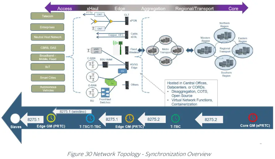
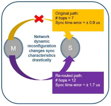 For tighter precision, this method of propagation is changing with more Grandmasters put in the network path and the Grandmasters are moving to the edge. Timing and synchronization over large segments of network has its challenges, especially when higher layer protocols and traffic engineering (TE) methods can dynamically re-route traffic based on network conditions.
With less hops, a good accuracy and precision can be maintained. Conceptually, this is similar to how low-latency applications require caching or mirroring of data locally onsite or at the edge. The figure shows how network dynamic reconfiguration could impact the sync characteristics at the end-point (PTP slave).
PTP Profiles
EdgeSync provides the flexibility and ease for customers to select one of the many PTP profiles provided to set the EdgeSync timing engine mode of operation. In the current release, both ports will be set to the same profile and not independently.
There are many different PTP profiles that have been specified based on specific industries like Telecom, Power, Broadcasting, Enterprise, etc. while a few others are being created. These profiles will put some restrictions on some of the configuration parameters that are part of the IEEE 1588 to make it simpler and targeted towards specific industry and deployment. Typically, the profile dictates the PTP domain value range, PTP over L2 (Ethernet) or IP/UDP, multicast or unicast or mixed mode, message rates, announce timeout, delay mechanism, datasets, etc. are customized per profile. This covers most of it but for some of the profiles some additional parameters also need to be specified.
With EdgeSync, the user can select one of these PTP profiles for the timing engine to operate in. To make it user friendly, once the profile is selected, internally EdgeSync software will set up the most of the PTP profile specific parameters to default values for that profile and it is up to the customer if they want to customize it further (like a power user).
Below is the list of PTP profiles that EdgeSync currently supports. More profiles will be added in future releases and this documentation will be updated accordingly.
IEEE 1588 Default Profile
This is the profile that is specified by IEEE 1588 Standard itself. It uses domain 0, PTP over IPv4/UDP and multicast mode of operation.
G.8275.1 Telecom Profile
This is one of the Telecom profiles specified by ITU-T and is recommended for new deployment or green-field networks comprising switches. It is expected that every node or element in the network is PTP-aware, or in other words, the network has full on-path support. This is used in conjunction with Synchronous Ethernet (SyncE) which provides the physical layer frequency synchronization. G.8275.1 uses L2 (Ethernet) multicast as PTP transport layer. This is a better option as using the physical layer assist for frequency and phase/time from PTP over packet network as it gives the best of both worlds.
With G.8275.1 profile and SyncE, a slave or the network is congruent if the PTP source and SyncE source is traced back to the same Grandmaster. If they are not, then it is said to be non-congruent. In either case, the SyncE frequency reference that is used by the slave should be traceable as specified in the Quality Level (QL) value in the ESMC messages.
The figure below shows the details of G.8275.1 telecom profile.

In the PTP::Clock page, additional configuration parameters are provided that are specific to G.8275.1 profile as shown below.
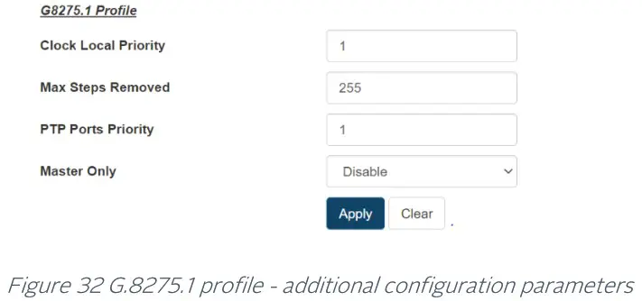 G.8275.2 Telecom Profile
This is another Telecom profile specified for legacy (brownfield) networks that work in conjunction with the older networks which can comprise switches and routers. This profile is used where there are network elements which are not PTP-aware and do not participate in PTP protocol processing. They act as pass-through elements but introduce additional delays which the end-points or slaves need to compensate for, to maintain timing precision. Since the sync path traverses over routers, this profile specifies PTP over UDP/IPv4 or UDP/IPv6 and unicast mode of operation. The figure below shows the details of G.8275.2 telecom profile.
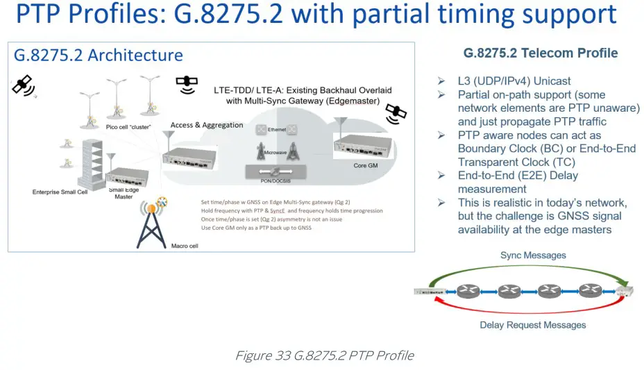
In PTP::Clock page, additional configuration parameters are provided that are specific to G.8275.2 profile as shown below.
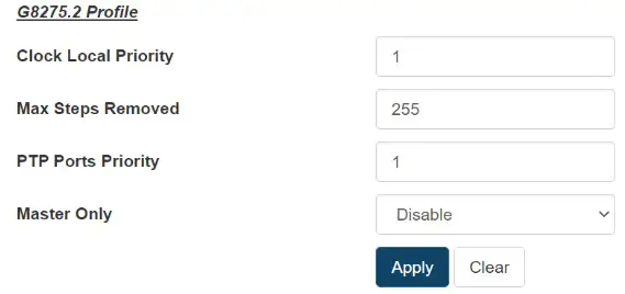
Figure 34 G.8275.2 profile – additional configuration parameters
G.8265.1 Telecom Profile
This is yet another Telecom profile from ITU-T for providing frequency-only synchronization (or syntonization) over packet network. This was specified to support legacy TDM networks like (SONET/SDH, etc.). It does not provide time/phase synchronization.
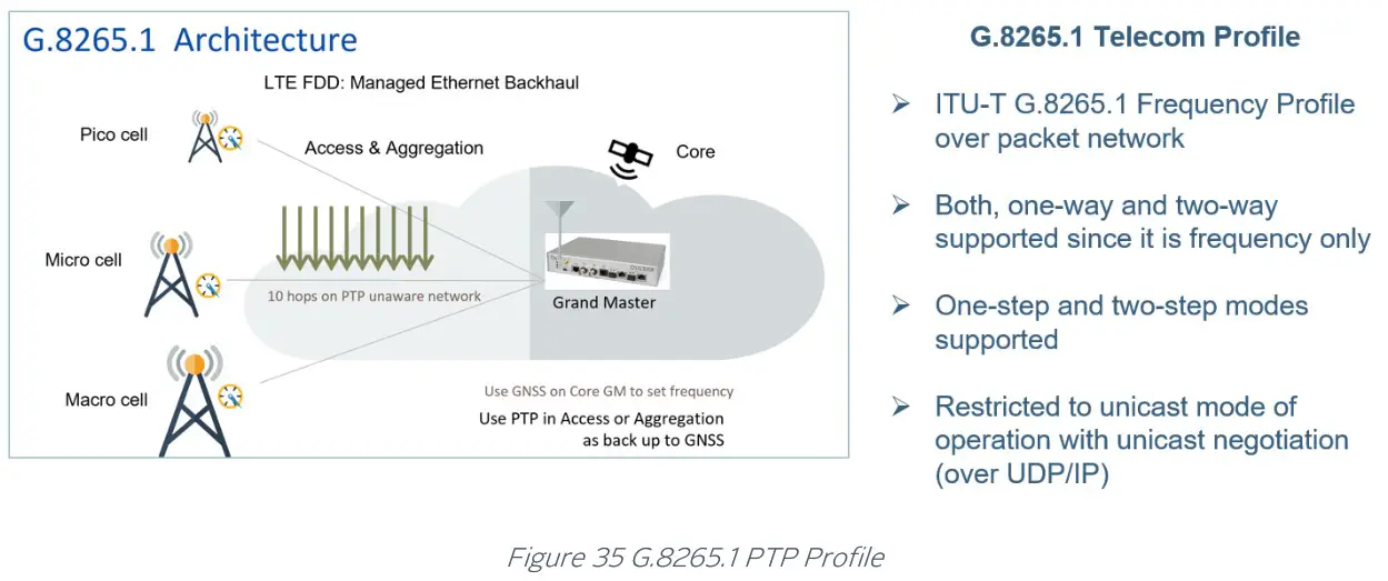
Power version-1 profile
This profile is specified for the power industry mainly in power system protection, control, automation, and data communication applications. This specific Power V1 is according to the IEEE C37.238-2011 standard. It uses PTP over L2 multicast, P2P delay mechanism and one of the salient features of this profile is that it uses priority tagging for VLAN (i.e., VLAN-id = 0, priority = 4).
In PTP::Clock page, additional configuration parameters are provided that are specific to Power Profile v1 as shown below.
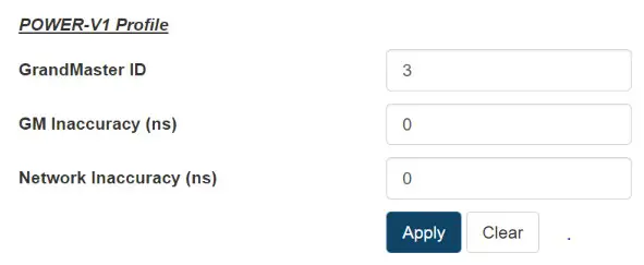
Figure 36 Power Profile v1 – additional configuration parameters
Power version-2 profile
This is version 2, 2017 edition of the power industry standards, IEEE C37.238-2017). One of the main differences from the 2011 edition is that there is no restriction on VLAN priority tagging on the PTP ports.
In PTP::Clock page, additional configuration parameters are provided that are specific to Power Profile v2 as shown below.
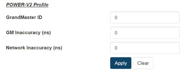
Figure 37 Power Profile v2 – additional configuration parameters
Power Utility Profile
This profile is specified as in Power Utility (IEC/IEEE 61850-9-3:2016) standard: Communication networks and systems for power utility automation Part 9-3: Precision time protocol profile for power utility automation. In many aspects, this is very similar to the Power v2 profile mentioned earlier.
In PTP::Clock page, additional configuration parameters are provided that are specific to the Power Utility profile as shown below.
Power Utility:
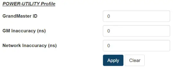
Figure 38 Power Utility Profile – additional configuration parameters
SMPTE Profile
SMPTE 2059 is a standard from the Society of Motion Picture and Television Engineers (SMPTE) that describes how to synchronize video equipment over an IP network. The standard is based on IEEE 1588-2008. SMPTE 2059 is published in two parts on 9 April 2015:
- SMPTE 2059-1 Defines signal generation based on time information delivered by the IEEE 1588 protocol.
- SMPTE 2059-2 Defines an operating profile for the IEEE protocol optimized to the needs of media synchronization.
The new television standard as specified by ATSC 3.0 uses SMPTE and for synchronization via IEEE 1588 v2. ATSC 3.0, also known by the moniker NextGen TV, is a major version of the ATSC standards for television broadcasting created by the Advanced Television Systems Committee (ATSC).
In PTP::Clock page, additional configuration parameters are provided that are specific to Power Utility profile as shown below.
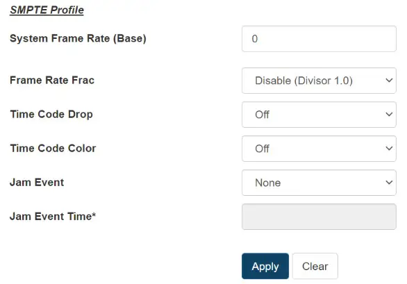
Figure 39 SMPTE Profile – additional configuration parameters
Synchronous Ethernet (SyncE)
What is Synchronous Ethernet?
Synchronous Ethernet feature is to help in providing frequency syntonization over packet based networks using Ethernet. It provides a mechanism to distribute frequency from Ethernet packet network to Time Division Multiplexed (TDM) circuits and nodes. For this, the (natively asynchronous) Ethernet physical layer is utilized in a fashion like (natively synchronous) SONET/SDH networks, with clock recovery and the assist of a new IEEE 802.3 slow-protocol packet called Ethernet Synchronization Messaging Channel (ESMC). This ESMC message is to convey the reference clock quality and traceability information in the form of Quality Level (QL). The SyncE feature is considered a physical layer characteristic unlike PTP which is in higher-layer software.
In current and next generation networks, there is need for time and not just frequency synchronization. That is, a combination of frequency, phase and time-of-day synchronization is required and expected to be delivered in a reliable and resilient fashion. Synchronous Ethernet can provide a stable frequency and can also be used as a local short-term holdover clock for maintaining time.
The Synchronous Ethernet standard is specified in ITU-T G.8262 and ESMC message in ITU-T G.8264.
SyncE feature in EdgeSync
Synchronous Ethernet feature is a configurable option on EdgeSync that can be enabled or disabled from the Home webpage, depending on the customer use-case and deployment. There are 4 main modes of operation in which SyncE feature can be deployed as described below. The PHY’s used in EdgeSync support SyncE in terms of supporting clock recovery on Ethernet Rx and being able to provide 125MHz clock externally for Ethernet Tx. This is supported with native RJ45 (1000BASE-T) PTP port interfaces and with optical 1GE SFP modules. SyncE is currently not supported on Copper SFPs.
SyncE in OFF mode
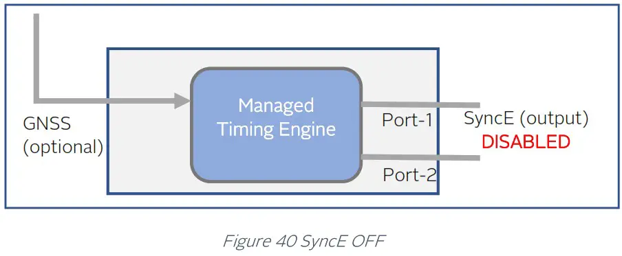
In this mode of operation, Synchronous Ethernet feature is turned off completely. Any incoming ESMC packets will be ignored and not processed, and no generation of outgoing ESMC packets. No clock recovery is done on Ethernet Rx. Frequency, along with phase and time are extracted from GNSS or PTP. This applies to both PTP ports.
SyncE in Master mode
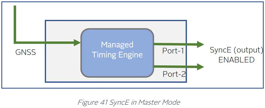
In this mode of operation, EdgeSync is in GNSS-only operating mode where it gets 1pps and ToD signals from a GNSS receiver (internal or external to EdgeSync), which was originally extracted from GNSS L1 signal. In this mode, the frequency, phase and time references are extracted from GNSS signal, and SyncE is output on both ports for frequency with ESMC/QL message distribution to next downstream L2 network node. The outgoing QL enumeration is PRC (for EEC Option-1) or PRS (for EEC Option-2) when locked to GNSS.
SyncE in Boundary Clock Mode
In Boundary Clock mode, SyncE feature can be enabled when engine is operating in PTP-only mode. In this mode, one of the PTP ports operates as a PTP-slave synchronizing to a PTP master upstream, while the other PTP port operates as a PTP-master distributing time and sync downstream to other PTP slaves.
There are some differences that should be noted when using L2 (Ethernet multicast) based PTP profile like G8275.1 and L3 based PTP profile like G8275.2. More details to follow in the sections below.
SyncE in Boundary Clock Mode for G8275.1 Telecom Profile
G8275.1 profile is specified for PTP clock distribution in a Layer-2 Ethernet multicast network. This network is expected to have full on-path support, i.e.. every node is PTP-aware and participates in the PTP protocol. When EdgeSync is put in Boundary Clock mode in this network, the input SyncE from upstream is used as frequency reference and used directly for SyncE distribution on downstream port, after getting cleaned up by the internal PLL in the clock engine.
On EdgeSync Home webpage, the SyncE selection provides the flexibility of specifying upstream port (PTP slave + SyncE reference input) and downstream port (PTP slave +SyncE output) and as shown in the figures below.
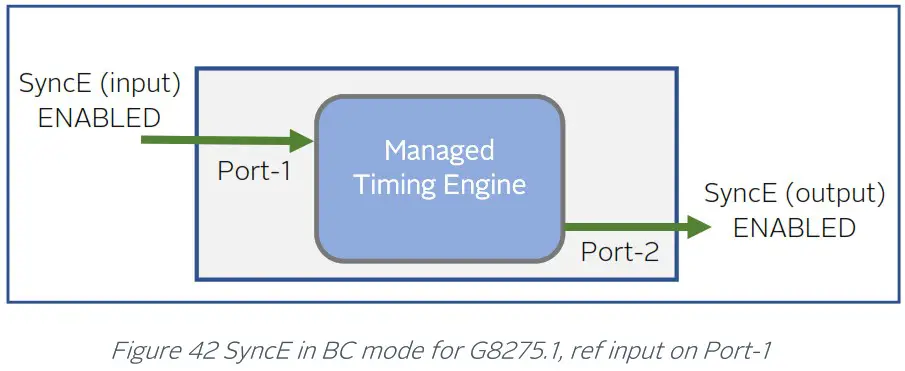
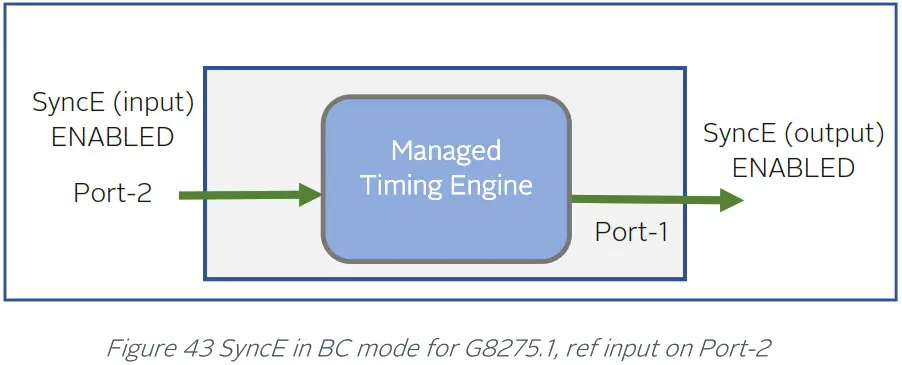
SyncE in Boundary Clock Mode for G8275.2 Telecom Profile
G8275.2 profile is specified for L3 unicast network and is based on partial timing support from the network. This means that not all network nodes may participate in PTP protocol. In this mode, SyncE input frequency reference can be used as a frequency assist for PTP. The physical layer (i.e. frequency) output is controlled by both, the input (from SyncE) and PTP engine. Unlike in G8275.1, here the physical layer output is NOT directly from input reference and hence not traceable and cannot be used for SyncE output distribution. SyncE output is disabled in this case.
The figures below show the flexibility of specifying the ports for operation in this mode.
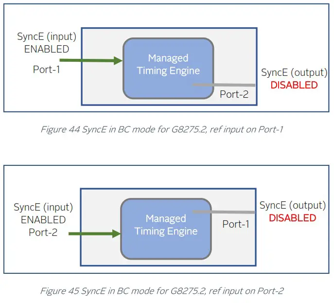
SyncE – status
The SyncE status is displayed at the bottom of PTP :: Port webpage.
SyncE Status in GM mode
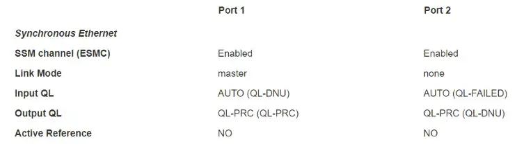
Figure 46 GM SyncE status output on PTP::Port webpage
The above figure is a sample status when EdgeSync is operating as a GM and Port1 is connected to a SyncE slave and Port2 is not connected to a link partner (link down condition). The following describes the different fields in this use case:
- SSM channel (ESMC) it is enabled for both ports.
- Link Mode This is applicable only for Copper/RJ45. This is as per 802.3 standard which specifies the physical media and the working characteristics of Ethernet. To work in conjunction with SyncE, link mode on EdgeSync ports will be (forced) set to master clock and 1000 Mbps full-duplex and auto-negotiation turned off. In the example above, there is a link on port-1 and its Link Mode set to “master”, while for port-2 there is no link, it shows as “none”.
- Input QL This is the Quality level in the ESMC message received on that port (from its link partner).
- For Port1, it indicates AUTO (QL-DNU), and
- For Port2, it indicates AUTO (QL-FAILED)
In GM mode, the input QL processing in EdgeSync is set to AUTO to take the input from the port and feed it into the PLL as one of the inputs. What is shown in the parentheses is the actual value received. - Port1, receives QL-DNU (DNU = do not use) from its link partner.
- Port2, since the link is down, it shows QL-FAILED.
- Output QL In this use case, the frequency reference is coming from GNSS (or 1pps) and not from either of the two Ethernet ports. The quality level for that is PRC (or PRS). This QL is what should be propagated downstream as the EdgeSync is a Grand Master.
- For Port1, the link is up and so the actual QL that is put in the outgoing ESMC message is QL-PRC as shown in the parentheses.
- For Port2, not that it matters since the link is down, the value that will be put in the ESMC message will be QL-DNU.
- Active Reference this will indicate YES or NO to indicate the recovery of frequency on that Ethernet port. The YES would mean that the frequency is recovered from this port. In a BC clock mode of operation with SyncE enabled, it will YES on the (slave)port where we get the frequency reference and NO on the other (master) port. In our sample use case of GM, it will show NO on both pots as the active reference is from GNSS (1pps) and not from the Ethernet ports.
SyncE Status in BC mode
![]()
Figure 47 BC SyncE status output on PTP::Port webpage
The above figure is a sample status of SyncE when EdgeSync is operating as a BC, getting the SyncE reference from Port1 and propagating it on Port2. Here, on port-2 a SFP optical module is used instead of the native RJ45 Copper port. The following explains the different fields for this use case:
- SSM channel (ESMC) – it is enabled for both ports. On Port1 it is recovered and on Port2 it is transmitted.
- Link Mode – this is as per 802.3 standard as mentioned in the previous GM use case.
- Port1: The link mode is in alignment with SyncE as this is a SyncE slave port and getting the frequency reference from its link partner.
- Port2: The link mode does not matter as it is not copper but is SFP optical. It is displayed as “master-slave”. If it had been Copper/RJ45, then it would have displayed as “master”.
- Input QL – This is the Quality level received on that port (from its link partner).
- For Port1, it indicates AUTO (QL-PRC) indicating that incoming SyncE ESMC has QLPRC. This is used as SyncE reference.
- For Port2, it indicates AUTO (QL-DNU) indicating that incoming SyncE ESMC has QLDNU.
- Output QL – This is the Quality level transmitted out on the port.
- For Port1, QL-DNU is sent out. This is required on the port that is being used as SyncE reference to avoid any clock loops
- For Port2, the AUTO indicates that we are transmitting QL that was received as reference. The actual value is QL-PRC, the frequency propagated from Port1 input.
- Active Reference – This will indicate YES or NO and pertains to recovery of frequency on a specific Ethernet port
- For Pot1, it is YES since the reference frequency is recovered here
- For Port2, it is NO since the recovered frequency is not used as reference
SyncE – some additional notes
Some additional notes regarding SyncE feature in EdgeSync:
- Synchronous Ethernet is supported only for 1GE interface speed. If user had configured previously on Interfaces::PTP webpage for a different Auto-Negotiation and speed parameters, they will be reset to 1000Mbps Full-duplex.
- For other profiles besides G8275.1 and G8275.2, the SyncE operation will depend on whether the profile is specified for L2-multicast or L3-unicast. If L2-multicast, then it will follow G8275.1 operation, and if L3-multicast, it will follow G8275.2 operation.
- SyncE operation is valid only in association with Operating Modes, GNSS-only and PTP-only. Synchronous Ethernet field should be set to off for other operating modes.
5G and Synchronization
As the reader may be aware, in 5G the base stations is decomposed into remote radio unit (RRU), distribution unit (DU), and the control unit (CU). For the proper functioning and getting optimal performance from RU, DU and CU in 5G RAN, precise timing and synchronization plays a crucial role. Not only just from RAN perspective, but also from an end-to-end network perspective for new applications and services like network slicing that run on 5G network.
For 5G RAN, the typical sync and time error budget is +/-1.5us from the core to RAN over the air (OTA) interface. For specific deployments and network operation use case scenarios, a higher precision or sync accuracy may be required. For Time Alignment Error (TAE) within a cluster of RUs, , all of which synchronizing from the same DU, it is +/-130ns. It should be noted that this budget is specified for synchronization and not latency.
Open RAN, ORAN deployment scenarios
EdgeSync is a simple yet powerful and flexible stand-alone timing and synchronization solution for todays and next generation networks. Specifically with the advent of commercial off the shelf hardware (COTS), open-source software and disaggregation concepts and technologies into Radio Access
Network (RAN).
Below shows the RAN Architecture evolution. Prior to 5G, the RAN architecture was such that the base stations are co-located with the Radio tower and all the layer-1 (or PHY or Radio) including analog/digital conversions at or near the radio. In 5G, with massive MIMO, millimeter wave with shorter range radios, and more end applications, there will be more radios (small cells, and towers). This is needed to provide the necessary coverage. The radios need to be small, economical, and efficient and located remotely for 5G. Centralized RAN, virtualized RAN and Open RAN are some of the new architectures that are gaining traction in this regard.
EdgeSync for 5G deployment
There is a lot of activity currently going on in 5G as the ecosystem evolves. There are legacy vendors (Ericsson, Huawei, Nokia, etc.) working with the carriers in building and deploying a single-vendor solution. Besides these legacy vendors and providers, a new host of companies have entered the 5G ecosystem. The basic driving factor for new players is that 5G is seen as a new technology that requires products from multi-vendors to be interoperable and there is no single vendor “lock-in”. Most of the hardware is off-the-shelf and the software is open source which empowers smaller players to enter into this market. Regardless of whether the network operator deploys a disaggregated multi-vendor or the legacy single-vendor infrastructure, precise timing and synchronization is critical.
Shown below is how EdgeSync can be deployed for the different configurations as specified in Synchronization plane (or S-plane) of ORAN Workgroup-4. The configurations are specified as LLS-C1 through LLS-C4, where LLS = low-level split. The recommendation by ORAN is to use G.8275.1 profile along with SyncE.
The figure below shows other deployment scenarios – for 5G using legacy network architecture for synchronization.
Physical Interfaces
Antenna input
SMA 50 ohm. Protected for shorted antenna. The EdgeSync provides 5.0 VDC bias to power remote active antennas that provide 40 dB gain. The antenna system supports cable length up to 50 meters with RG59/RG58 and 50 to 100 meters with LMR500/LMR600.
Console
The console port uses mini-USB serial terminal protocol. The connector is on the front panel and the default settings are as follows:
- Baud = 115.2K
- Data Bits = 8 bits
- Parity = None
- Stop Bits = 1
- Flow Control = None
When Hard Reset Button is pushed and held for a longer duration (at least 10 seconds), it will do a factory reset of the unit followed by a reboot. The current configuration of EdgeSync will NOT be preserved and the user should save and restore their configuration as needed.
Note: It should be noted that using the Hard Reset Button should be a last resort consideration as it is abrupt and not a graceful way.
Hard Reset Button – Quick Push for Reboot
When Hard Reset Button is pushed and held for a short duration (approx. 1 or 2 seconds), it will reboot the unit. The current configuration of EdgeSync is preserved.
Hard Reset Button – Long Push for Factory Reset
When Hard Reset Button is pushed and held for a longer duration (approx. 10 seconds), it will do a factory reset of the unit followed by a reboot. The current configuration of EdgeSync will NOT be preserved and the user should save and restore their configuration as needed.
Important Note: Do NOT power cycle or do another reset of the EdgeSync until the long push button reset is finished and the system comes back in normal operation mode. This is indicated by the power LED turning green or EdgeSync log on Alarms/Events page indicates that it is ready for operation. Prematurely cutting off power or doing another reset after a long push button reset could potentially make the unit non-operational permanently and cannot be fixed in the field or customer site.
Management interface
Management port is 10/100BaseT RJ45. The Management port supports DHCP, HTTP Webpages, XML, SNMP (v2,v3), and SSH remote login.
Frequency Out port
BNC 50 ohm. 3.3V LVTTL DC blocked. Frequency Out selectable on the PTP :: Config Webpage.
1PPS timing output
BNC High Impedance 3.3V LVTTL output.
Time-of-Day / 1PPS input/output
ToD / 1PPS port is RJ45, input/output. The pin-outs for this RJ45 connector are defined in ITU-T G.703 Transmission Systems and Media, Digital Systems and Networks, Section 19. For more information about ITU-T G.703, see Error! Reference source not found..
The Time-of-Day Input format is selectable on the Interface :: GNSS Webpage and the Time-of-Day Output format is selectable on the Interface :: ToD/1PPS Output Webpage. The selections for both input and output are NMEA, ASCII text and China Mobile.
PTP interface, Port 1 and Port 2
Two Electrical RJ45 ports and two SFP ports. Each RJ45 port can support triple-speed (10/100/1000 Mbps) and each SFP port can support 1GE.
For Port 1, the same PTP messages/packets will be present in both the RJ45 and SFP connections, but the data rates may be different depending on the speed of the network to which they are connected.
For Port 2, the same PTP messages/packets will be present in both the RJ45 and SFP connections, but the data rates may be different depending on the speed of the network to which they are connected.
SFP (and SFP+) optical modules for PTP Port 1 and 2
SFP optical modules can be plugged into the PTP ports for Ethernet connectivity instead of the electrical RJ45 ports. These ports have been designed for standard SFP 1GE modules and dual-rate SFP+ modules operating at 1GE speed.
Orolia has verified the operation with modules from leading vendors as shown below:
Finisar: FTRJ8519P1BNL, FCLF-8521-3, FTLF1318P3BTL (available from Orolia as SFP-FIBER-SM)
Intel: AFBR709DMZ-IN3
Avago: AFBR-709SMZ, AFBR-5710LZ (available from Orolia as SFP-FIBER-MM)
Ubiquity: UF-MM-1G
FiberStore (FS): H3C SFP-10GSR-85 (SFP+ dual-rate configured for 1GE)
NOTE: SFP Copper modules are also available and will work with EdgeSync. The user should be aware that in that case, the PHY is inside the SFP Copper and in most cases will not fully support Synchronous Ethernet feature. In that case, we recommend using the native electrical RJ45 ports on EdgeSync.
LED Description
The EdgeSync has 3 LED’s on the front panel which communicates the status of the Power, GNSS Signal and Sync Status.
Power
| Power LED state | Description |
| Red | Any of the internal voltages are in alarm state |
| Amber/Orange | Initial boot and OS load completed successfully. Loading Applications. |
| Green | HW and SW Applications loaded and ready for normal operation |
| Green – blinking | EdgeSync software upgrade in progress – do NOT reboot or turn power off! |
| Red – blinking | Previous attempt to upgrade software on EdgeSync failed |
GNSS
| GNSS LED state | Description |
| Off | MCE not running or MCE running in PTP only mode or software upgrade in progress |
| Red | 1PPS Input Error or ToD Input Error |
| Green | Signal acquired, 1PPS Input or ToD Input Available |
Sync Status
| Sync Status LED state | Description |
| Off | MCE not running or software upgrade in progress |
| Red | MCE running, Not Synchronized and engine state is FREE RUNNING |
| Amber | MCE running, Not Synchronized and engine state is SYNCHRONIZING, SYNTONIZING or HOLDOVER |
| Green | MCE running, Locked / Synchronized |
Power
The options are -48 VDC, (-34 to -60 VDC supply) or 28 – 40 VAC. 17-25W power consumption, depending on oscillator option.
| Estimated Power Consumption based on Oscillator Option | |
| Oscillator Option | Power Consumption |
| OCXO | 17 watts |
| HP OCXO | 25 watts |
Physical dimensions
Size: 218 (W) x 160 (D) x 43 (H) mm excluding connectors Weight: 1.01 kg
Part Numbers
| Part Number | Description |
| 100-925-02 | EdgeSync, OCXO, 32 PTP Unicast Slaves |
| 100-927-03 | EdgeSync+, HP OCXO, 128 PTP Unicast Slaves |
Glossary
| Acronyms and Abbreviations | |
| 1PPS | Pulse Per Second |
| 1RU | 1 Rack Unit, 1.75 inches or 44.45 millimeters |
| API | Application Program Interface |
| ASCII | American Standard Code for Information Interchange |
| BaseT | Megabits / second Transferred over CAT5 cable |
| BC | Boundary Clock |
| BMCA | Best Master Clock Algorithm |
| BNC | Bayonet Neill-Concelman connector |
| CAT5 | Category 5 cable |
| CLI | Command Line Interface |
| C-RAN | Cloud-Radio Access Network |
| DHCP | Dynamic Host Configuration Protocol |
| DNS | Domain Name Server |
| DST | Daylight Savings Time |
| E2E | End to End delay measurement mechanism |
| ESD | Electrostatic Discharge |
| ETH | Layer 2 network communication for PTP messages |
| FTP | File Transfer Protocol |
| FW | Firmware |
| GC | Gateway Clock |
| GM | Grand Master |
| GNSS | Global Navigation Satellite System |
| GPS | Global Position System |
| HMI | Human Machine Interface |
| HTTP | HyperText Transfer Protocol |
| IEEE | Institute of Electrical and Electronics Engineers |
| IPv4 | Internet Protocol version 4 |
| IPv6 | Internet Protocol version 6 |
| LAN | Local Area Network |
| LED | Light-emitting Diode |
| MAC | Media Access Control address |
| Mbps | Megabits per second |
| MGMT Port | Management Port |
| MHz | Megahertz Frequency |
| Mini-USB | Mini Universal Serial Bus |
| MCE | Managed Clock Engine |
| NMEA | National Marine Electronics Association |
| NV | Nonvolatile Memory |
| OC | Ordinary Clock |
| OCXO | Oven Controlled Crystal Oscillator |
| P2P | Peer to Peer delay measurement mechanism |
| PLL | Phase Locked Loop |
| PoE | Power over Ethernet |
| PTP | Precise Time Protocol |
| PWR | Power |
| RF | Radio Frequency |
| RU | Rack Unit |
| RMC | Recommended Minimum data for GPS, Sentence C from NMEA |
| SFP | Small Form-Factor Pluggable transceiver |
| SFTP | SSH File Transfer Protocol or Secure File Transfer Protocol |
| SMA | SubMiniature version A connector |
| SNMP | Simple Network Management Protocol |
| SSH | Secure Shell cryptographic network protocol |
| ToD | Time of Day |
| TTL | Transistor-transistor Logic |
| TZ | Time Zone |
| UDP | User Datagram Protocol, IPv4. Layer 3 network communication |
| UDP6 | User Datagram Protocol, IPv6. Layer 3 network communication |
| UIP | User Interface Processor |
| UTC | Coordinated Universal Time |
| VAC | Voltage Alternating Current |
| VDC | Voltage Direct Current |
| WAN | Wide Area Network |
| XML | eXtensible Markup Language |
| ZDA | Data and Time from GPS, NMEA standard |
References
- IEEE1588-2008 IEEE Standard for a Precision Clock Synchronization Protocol for Networked Measurement and Control Systems
- ITU-T G.703, Physical/electrical characteristics of hierarchical digital interfaces
Revision History
| Revision Number | Software Version | Release Date | Updates |
| 1 | 12.1.26 | Oct-21 | First Generation EdgeSync Manual |
| 2 | 12.1.27 | Nov-21 | Added an Important Note on GNSS Clock Class mapping, updated note to not do another reset after a long push button reset for factory default. Corrected minor errors. |
Contact
Should you have any questions or comments please visit the following link, where you can request product information or technical assistance:
orolia.com/support/
You can also email Technical Support directly at:
[email protected]
– End of document –


