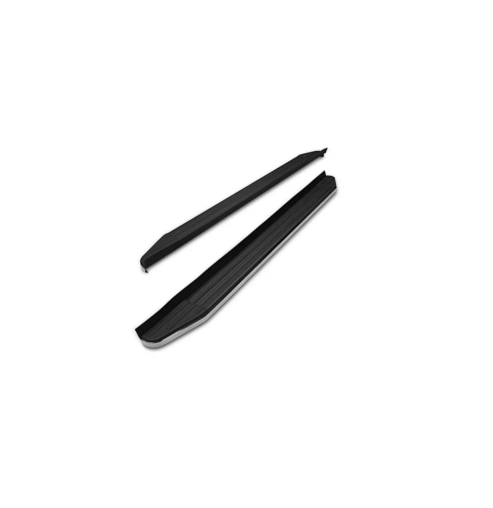
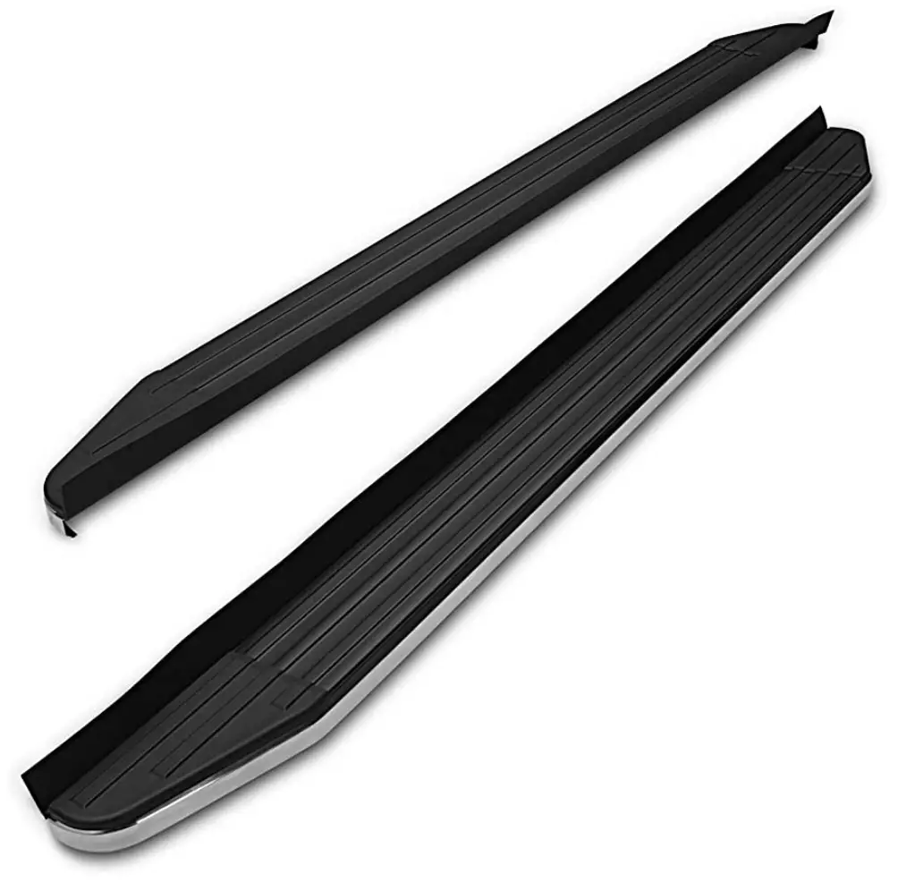
TAC 104300 Chevy Trailblazer
PARTS LIST
| 1 | Driver/Left Viewpoint Running Board | 2 | Compression Plates |
| 1 | Passenger/Right Viewpoint Running Board | 6 | 10mm x 40mm Large Bolt Plates |
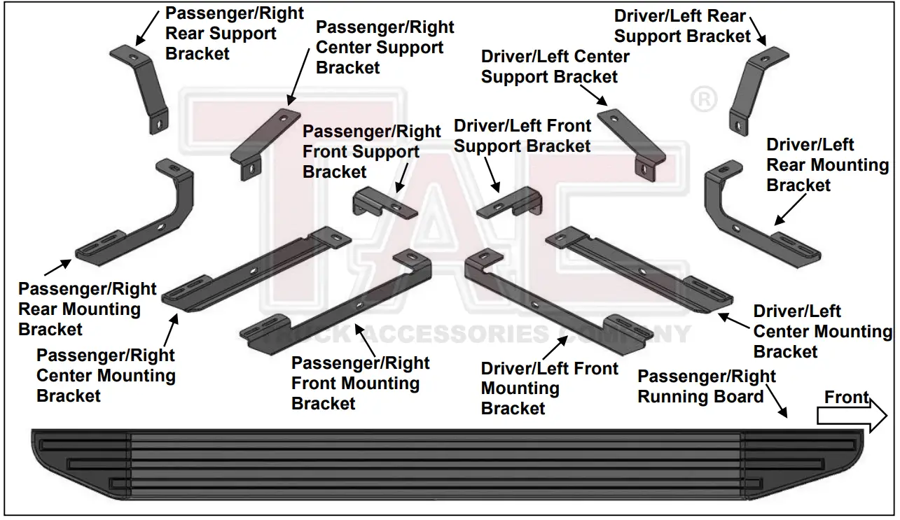
| 1 | Driver/Left Front Mounting Bracket | 6 | 10mm x 30mm Small Bolt Plates |
| 1 | Passenger/Right Front Mounting Bracket | 2 | 10mm x 45mm Hex Bolts |
| 1 | Driver/Left Center Mounting Bracket | 6 | 10mm x 30mm Hex Bolts |
| 1 | Passenger/Right Center Mounting Bracket | 12 | 10mm x 30mm OD x 2.5mm Flat Washers |
| 1 | Driver/Left Rear Mounting Bracket | 14 | 10mm x 20mm OD x 2mm Flat Washers |
| 1 | Passenger/Right Rear Mounting Bracket | 20 | 10mm Lock Washers |
| 1 | Driver/Left Front Support Bracket | 20 | 10mm Hex Nuts |
| 1 | Passenger/Right Front Support Bracket | 12 | 10mm Plastic Retainers |
| 1 | Driver/Left Center Support Bracket | 12 | 6mm x 20mm T-Bolts |
| 1 | Passenger/Right Center Support Bracket | 12 | 6mm x 22mm OD x 2mm Flat Washers |
| 1 | Driver/Left Rear Support Bracket | 12 | 6mm Lock Washers |
| 1 | Passenger/Right Rear Support Bracket | 12 | 6mm Hex Nuts |
PROCEDURE
- REMOVE CONTENTS FROM BOX. VERIFY ALL PARTS ARE PRESENT. READ INSTRUCTIONS CAREFULLY. ASSISTANCE IS HIGHLY RECOMMENDED.
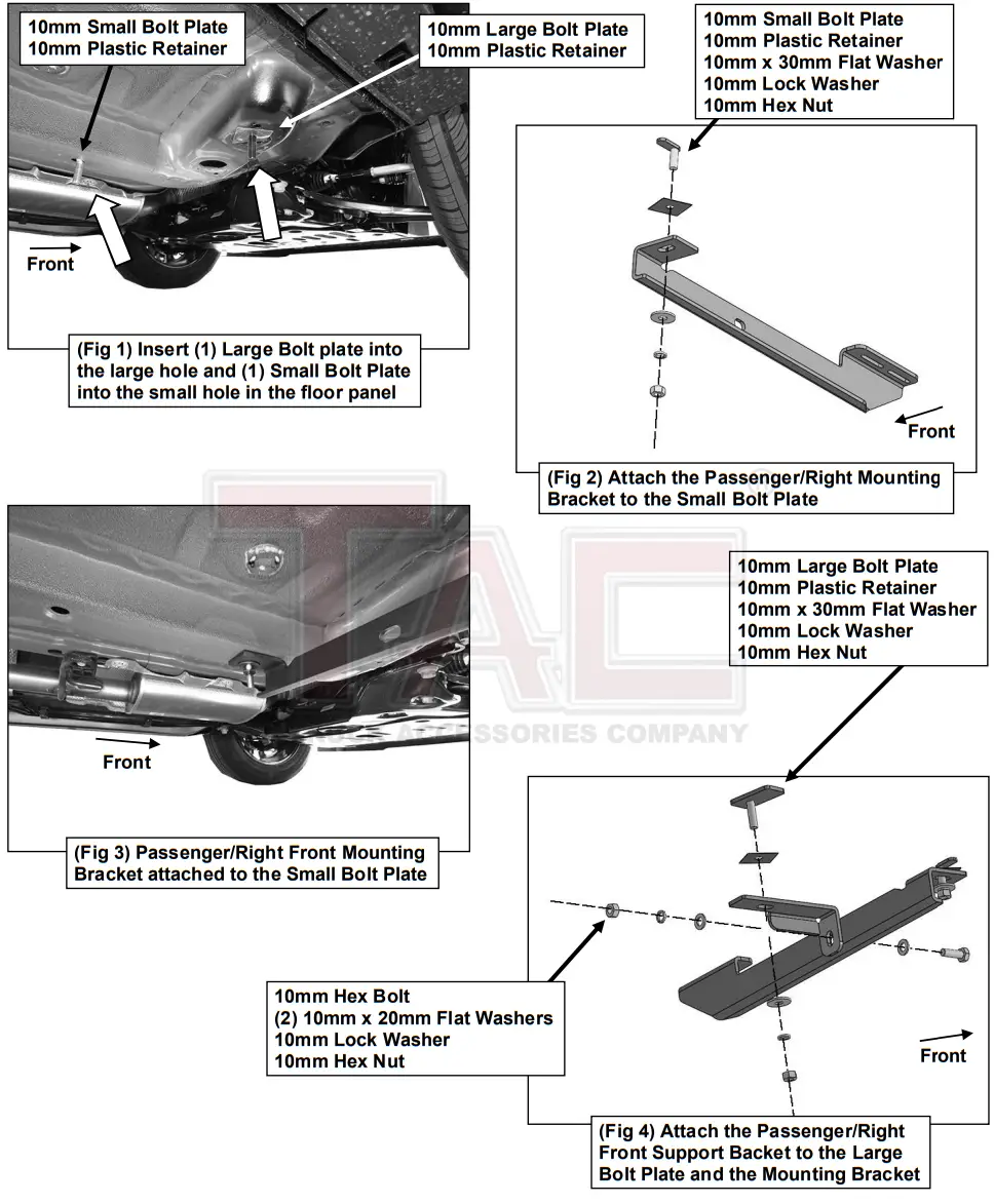
- Starting on the Passenger/Right side of the vehicle, locate the front mounting location, (Figure 1). Select (1) Large 10mm Bolt Plate and thread (1) 10mm Plastic Retainer onto the threads. Insert into the large hole in the floor panel, (Figure 1). Select (1) Small 10mm Bolt Plate and thread (1) 10mm Plastic Retainer onto the threads. Insert into the small hole in the floor panel, (Figure 1).
- Select the Passenger/Right Front Mounting Bracket. Attach the Mounting Bracket to the Small Bolt Plate with (1) 10mm x 30mm Flat Washer, (1) 10mm Lock Washer and (1) 10mm Hex Nut, (Figures 2 & 3). Do not tighten hardware.
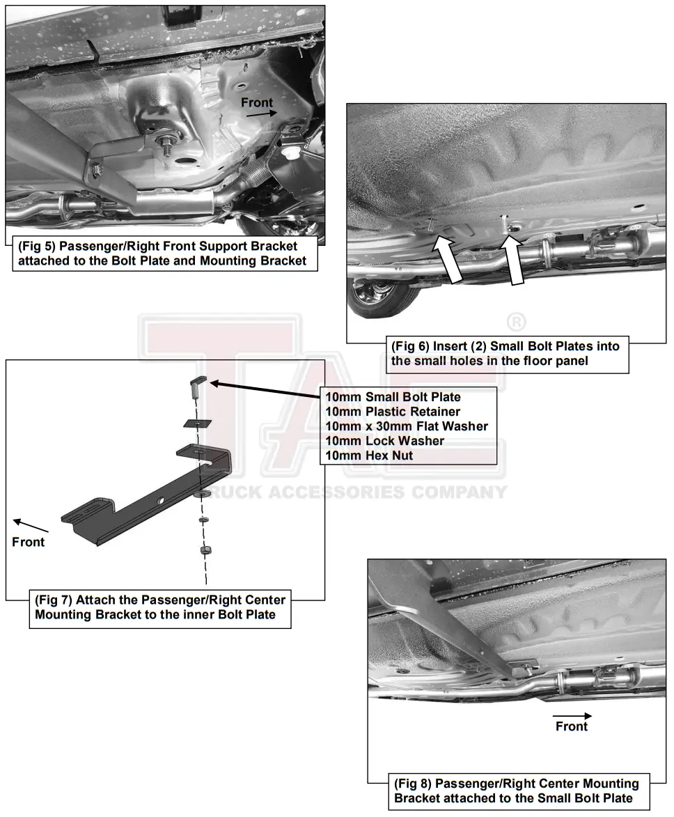
- Select the Passenger/Right Front Support Bracket. Attach the Support Bracket to the Large Bolt Plate in the floor panel with (1) 10mm x 30mm Flat Washer, (1) 10mm Lock Washer and (1) 10mm Hex Nut. Attach the Support Bracket to the Mounting Bracket with (1) 10mm Hex Bolt, (2) 10mm x 20mm Flat Washers, (1) 10mm Lock Washer and (1) 10mm Hex Nut, (Figures 4 & 5). Do not tighten hardware.
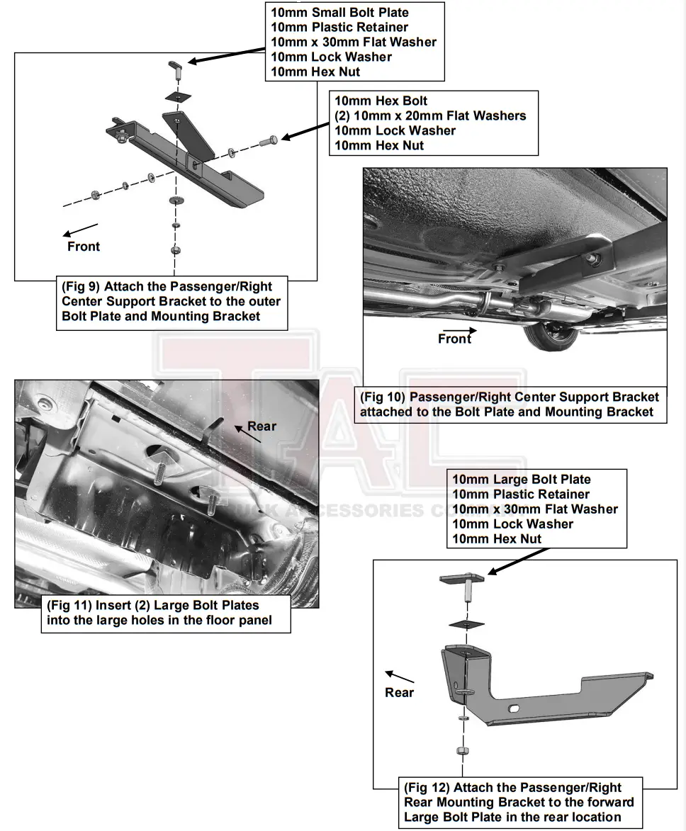
- Move to the center location, (Figure 6). Select (2) 10mm Small Bolt Plates and thread (1) 10mm Plastic Retainer onto each of the threads. Insert the (2) 10mm Small Bolt Plates into the holes in the floor panel, (Figure 6). Repeat Steps 3 & 4 to attach the Passenger/Right Center Mounting Bracket and Center Support Bracket, (Figures 6—10). NOTE: Attach the Mounting Bracket to the forward Bolt Plate and the Support Bracket to the rear Bolt Plate.
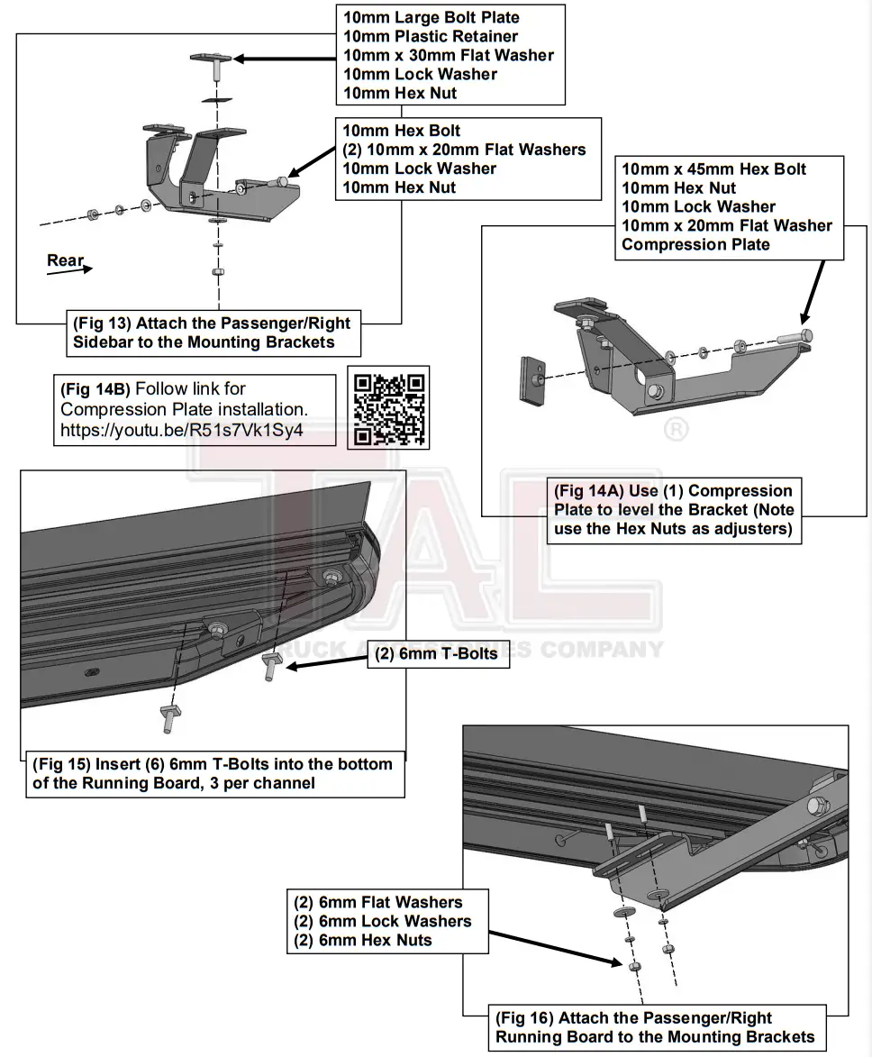
- Move to the rear mounting location, (Figure 11). Select (2) 10mm Large Bolt Plates and thread (1) 10mm Plastic Retainer onto each of the threads. Insert the (2) 10mm Large Bolt Plates into the large holes in the floor panel, (Figure 11). Repeat Steps 3 & 4 to attach the Passenger/Right Rear Mounting Bracket and Rear Support Bracket to the (2) Large Bolt Plate, (Figures 12 & 13). Do not tighten hardware. NOTE: Attach the Mounting Bracket to the forward Bolt Plate and the Support Bracket to the rear Bolt Plate.
- Select (1) Compression Plate.
a. Thread (1) 10mm Hex Nut to (1) 10mm x 45mm Hex Bolt.
b. Slide (1) 10mm Lock Washer and (1) 10mm Flat washer onto the 10mm Hex Bolt.
c. Thread the 10mm Hex Bolt assembly into the welded nut on the back of the Mounting Bracket.
Place the Compression Plate onto the end of the 10mm Hex Bolt, (Figures 14A & 14B).
d. Tighten Hex Bolt to place the Compression Plate onto the floor panel. Do not tighten Hex Bolt all the way. NOTE: Use the 10mm Hex Nut to adjust the level of the Mounting Bracket.
e. Follow link for Compression Plate installation. https://youtu.be/R51s7Vk1Sy4
- Select the Passenger/Right Viewpoint Running Board. Insert (6) T-Bolts into the channels in the bottom of the Running Board, (3) per channel, (Figure 15). Place the Running Board onto the Mounting Brackets and line up the T-Bolts. Attach the Running Board to the Mounting Brackets with (6) 6mm Flat Washers, (6) 6mm Lock Washers and (6) 6mm Hex Nuts, (Figure 16). Do not tighten hardware.
- Level and adjust the Running Board and fully tighten all hardware.
- Repeat Steps 1—9 to attach the Driver/Left Viewpoint Running Board.
- Do periodic inspections to the installation to make sure that all hardware is secure and tight.
To protect your investment, Do not use any type of polish or wax that may contain abrasives that could damage the finish. Use only mild soap to clean the Running Boards.
Passenger/Right Side Installation Pictured