GODZILLA CG-007 Smart Key Cutting Machine User Manual
![]()
![]()
Please read instruction carefully before using.
Disclaimer and Limitation of Liability
All information and illustrations in the manual are the latest information. Shenzhen Changguang Technology Co., Ltd. reserves the right to make changes without notice.
Our company does not bear any direct, indirect, special, incidental damages or any indirect economic damages.
Note:
Before operating or maintaining the equipment, please read this manual carefully, especially the safety precautions and warnings.

Safety Precautions
In order to ensure the safety of the operator, and to avoid damage to the machine/key and property loss, the operator must carefully read this operation manual before using the machine and observe the following safety precautions:
![]() Please take out the device support plate when using.
Please take out the device support plate when using.
![]() Always operate the machine in a safe environment.
Always operate the machine in a safe environment.
![]() During operation, please wear goggles that comply with ANSI standard.
During operation, please wear goggles that comply with ANSI standard.
![]() During the operation of the machine please do not keep clothes, hair, hands, and other tools near the key cutting area.
During the operation of the machine please do not keep clothes, hair, hands, and other tools near the key cutting area.
![]() Do not place the device in a humid, dusty, or direct sunlight environment for a long time.
Do not place the device in a humid, dusty, or direct sunlight environment for a long time.
![]() Do not have heavy pressure, fading, immersion device and other behaviors.
Do not have heavy pressure, fading, immersion device and other behaviors.
![]() If not used for a long time, it is recommended to unplug the power supply.
If not used for a long time, it is recommended to unplug the power supply.
![]() Please use original lithium battery or power adapter.
Please use original lithium battery or power adapter.
![]() In the event of an abnormality, turn off the power immediately.
In the event of an abnormality, turn off the power immediately.
Product Description
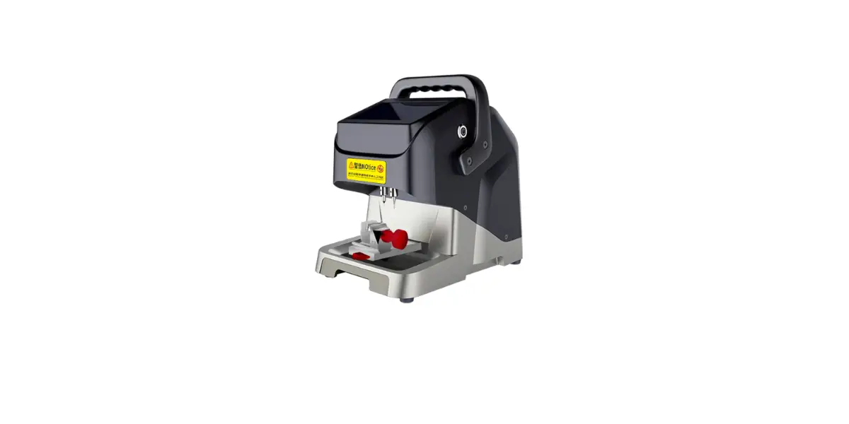
Godzilla Key Cutter is easy to carry with super powerful and advanced Design. It is a new generation of key processing device tailored for global locksmiths. It is equipped with a 7.0-inch LCD operation screen, which is easy to operate and can be quickly and accurately copy all kinds of car keys.
Features
Godzilla Key Cutter has following features:
![]()
7 inch LCD operation screen.
![]() Portable and exquisite, built-in large capacity lithium battery, ultra long continuous cutting ability.
Portable and exquisite, built-in large capacity lithium battery, ultra long continuous cutting ability.
![]() Standard dual fixture T1 / T2.
Standard dual fixture T1 / T2.
![]() Support external milling / internal milling, etc.
Support external milling / internal milling, etc.
![]() Allaluminum structure.
Allaluminum structure.
![]() High precision imported lead screw with high cutting efficiency.
High precision imported lead screw with high cutting efficiency.
![]() High-rigidity cross guide rail for smoother operation.
High-rigidity cross guide rail for smoother operation.
![]() Support multiple languages.
Support multiple languages.
![]() Automatic network update.
Automatic network update.
Note:
Lithium battery is optional purchase product.
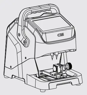
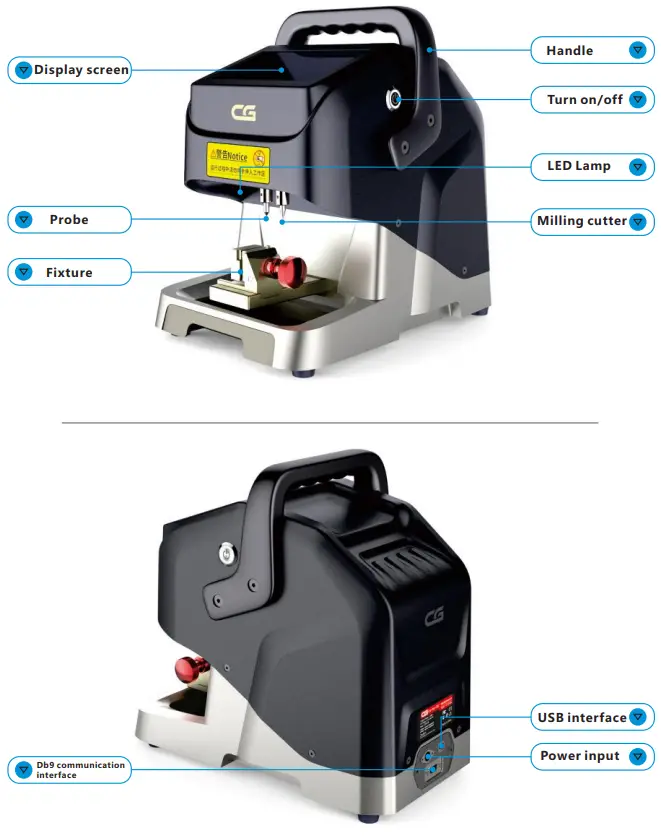
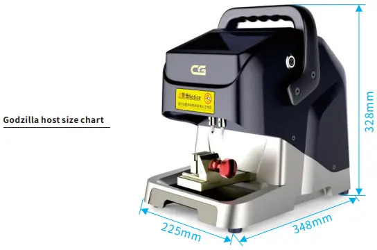
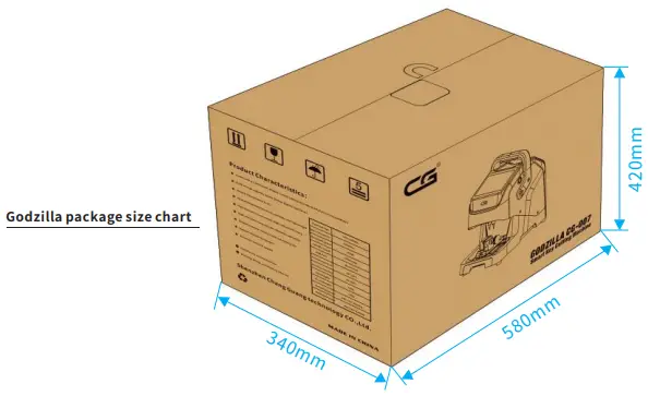
Product Structure Diagram
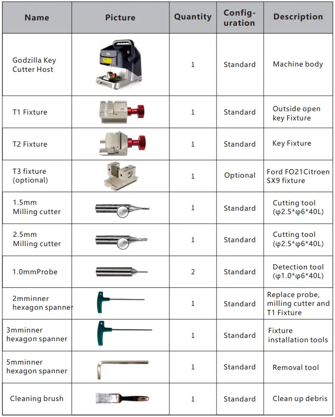
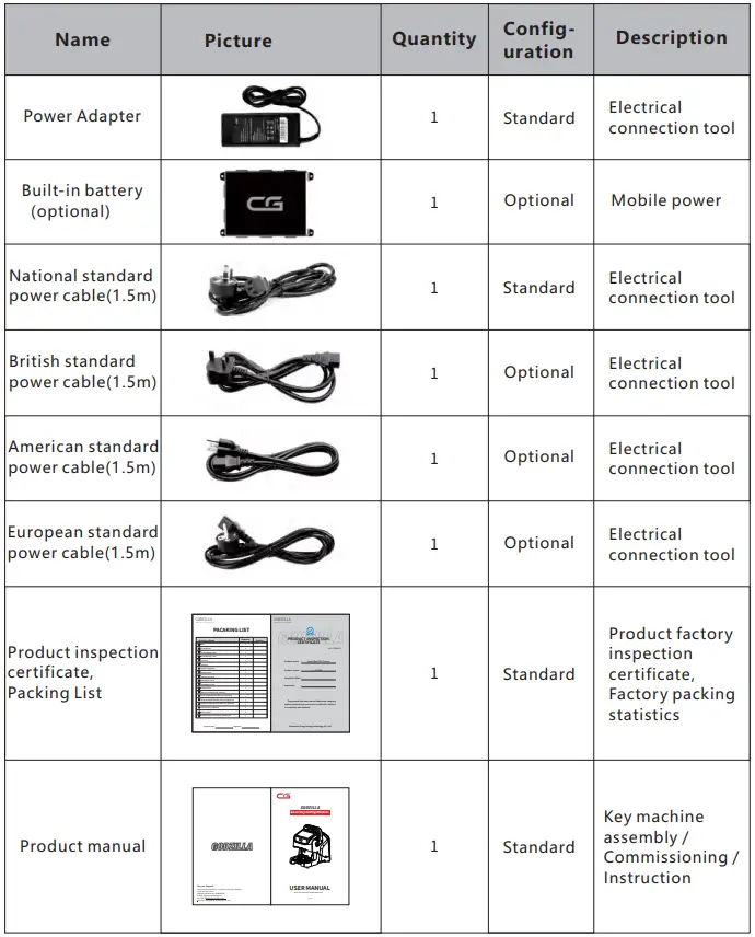
Product List
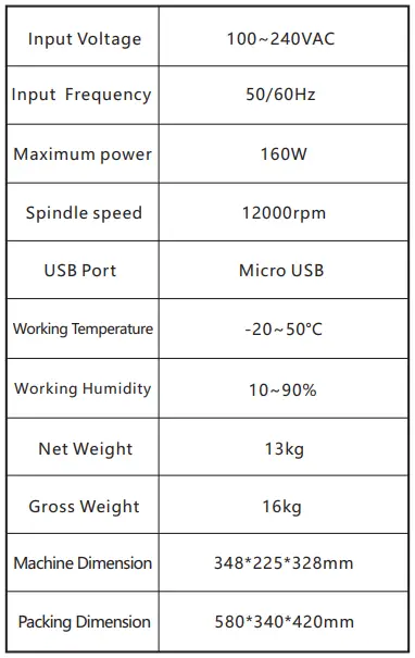
Product Specifications
Installation instructions
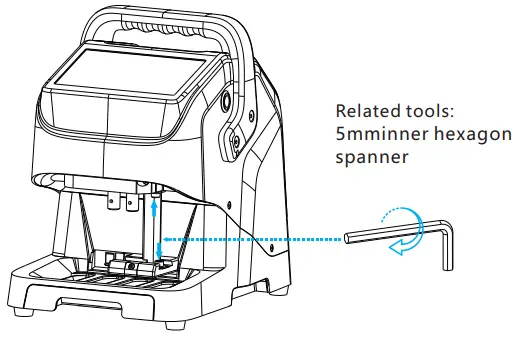
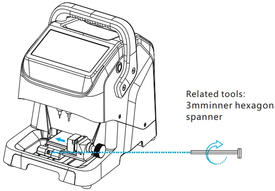
Support plate removal
Support plate removal steps:
- As shown above picture, firstly counterclockwise turn the “support plate locking screw” above the support plate until removed the screw.
- Secondly counterclockwise turn the “support plate locking screw” below the su- pport plate until removed the screw, and finally remove the support plate.
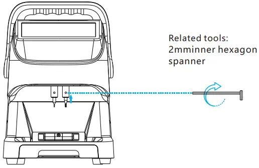
Milling cutter and probe installation
Milling cutter and probe installation steps:
- As shown above above, firstly turn counterclockwise the “milling screw” , then insert the milling cutter into the mounting hole of the milling cutter, push it up to the limit, and then move it down to a certain distance (2-5mm). Finally clockwise turn the “milling screw” until the milling cutter is locked.
- Refer to step 1 for the installation of the probe, and make sure that the end of the probe is higher than the milling cutter.
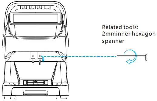
Milling cutter and probe Disassembly
Disassembly steps of milling cutter and probe:
- As shown in picture, counterclockwise turn the “milling cutter/ probe top tightening screw”until the milling tool or probe is loosened, and then remove it.
Fixture
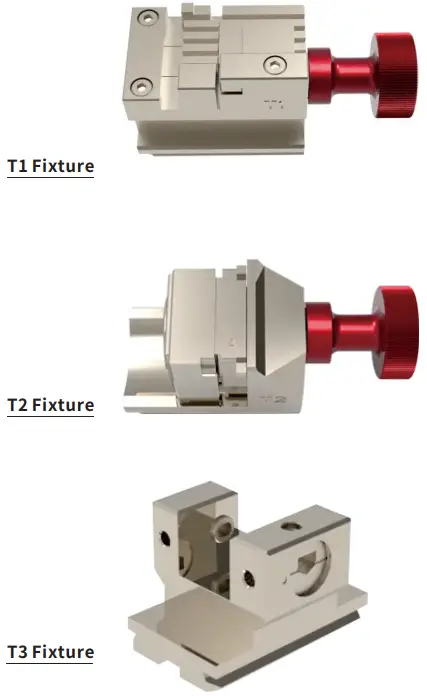
Fixture installation
Fixture installation steps:
- As shown in picture, firstly loosen the “fixture locking device” to to make it easier to place the fixture;
- Secondly, push the required fixture into the “fixture locking device” from the right side to the limit position;
- Finally, tighten the “fixture locking device” to fully lock the fixture.
Operation instructions
Please calibrate for the first-time turn on the device,as follow:
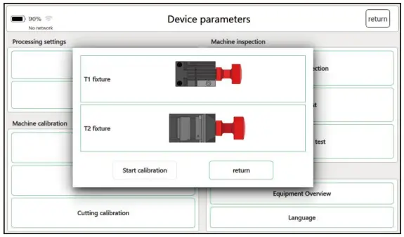
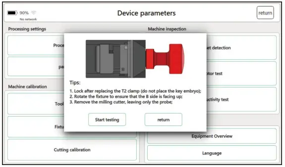
Fixture offset detection
- On the main interface of software, click “Device Parameters”.
- On the “Device Parameters” interface, click “Fixture offset detection”.
- On the “Fixture offset detection” interface, select “T1 fixture”.

- Follow the interface prompts, replace the T1 fixture and lock it, then click “Start Inspection” to enter the calibration program.
- After the machine steady stopped , click “return” to exit the interface and complete T1 fixture offset detection.
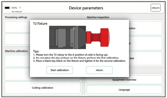
- Select “T2 fixture” in the “fixture offset detection” interface.
- According to the interface prompt, replace the T2 fixture, keep the B side upward, and then click “start detection” to enter the calibration procedure.
- After the machine steady stopped , click “return” to exit the interface and complete T2 fixture offset detection.
- This step is already calibrated at the factory, and it is recommended to re- calibrate after replacing the new fixture (the original fixture is damaged or lost during the cutting process) (Note: After completed the calibration , the replacement between the T1 and T2 fixtures not need to re-calibrated).
Leveling the changed height
- On the main interface of the software, click “Device Parameters”.
- On the “Device Parameters” interface,click“Leveling the changed height”.
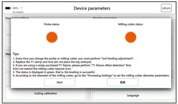
- Follow the instructions on the interface to replace the T1 fixture and lock it., and then click “Start” to enter the Leveling process.
- After the machine steady stopped, you can adjust the milling cutter and the probe. When both states show green light, it is leveled.
- Tighten the cutter and probe, and click “Exit” to complete the leveling.
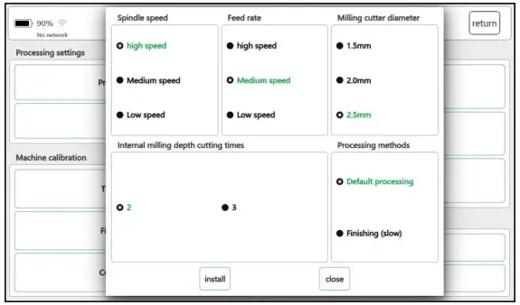
- After the machine steady stopped, according to the installed milling cutter diameter, click “Processing Settings”, select the corresponding milling cutter diameter on the interface depending on the actual needs, and click “Settings” to complete the setting, and then click “Close” to exit.
Leveling the changed height
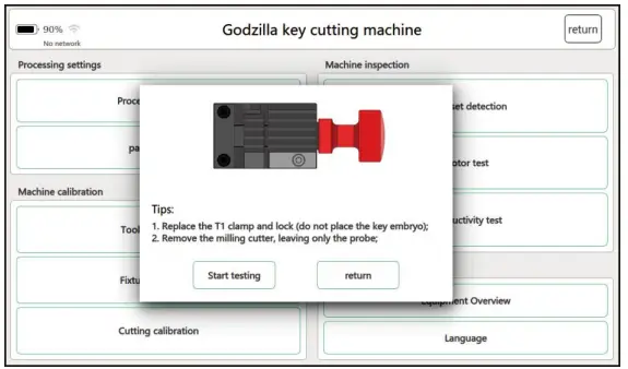
- On the main interface of the software, click “Device Parameters”.
- After entering the self-test page, click on “tool leveling”.
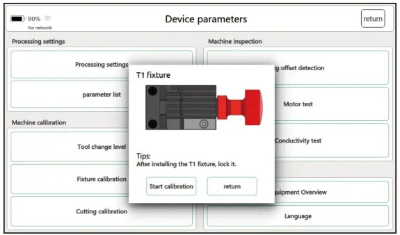
- Select “T1 Fixture” in the “fixture calibration” interface.
- Following the prompts, replace the T1 fixture and lock it, click “start calibration”and wait for the calibration to complete.
- After the calibration is complete, click “Back”.
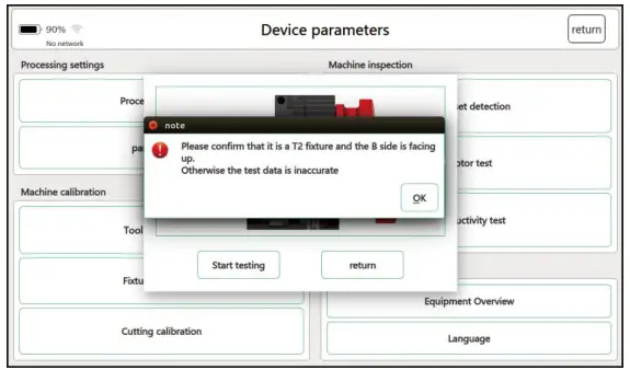
- Select “T2 fixture” in the “fixture calibration” interface and then click “T2A”.
- Enter the calibration of the A side of the T2 fixture, replace the T2 fixture and lock it according to the prompts, rotate the fixture to the A side up, and then click “Start Calibration”
- After completing the calibration, place a blank key on side A and clamp it, and click “Start Calibration” again
- After completing the calibration, click “Exit” to finish the calibration of the T2 fixture A side.
- Then complete the calibration of T2b, T2C and T2D in turn, and the installation interface prompts calibration.
- After all four sides are calibrated, T2 fixture calibration is completed.
- This step is already calibrated at the factory, and it is recommended to recalibrate after replacing the new fixture (the original fixture is damaged or lost during the cutting process) (Note: After completed the calibration , the replacement between the T1 and T2 fixtures not need to re-calibrated).

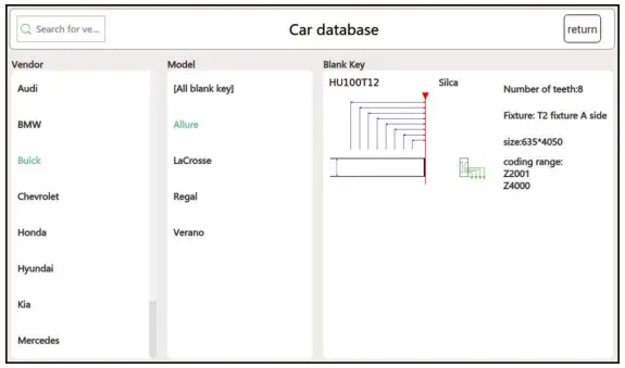
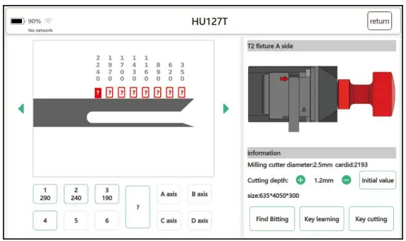
Car Database
- Firstly determine the model and year of the car when copy key. On the main interface of the key cutter, click “Car Database” to enter the next page.

- Enter the vehicle manufacturer or model in the search box, or select the model from the list, and click to enter the next page.

- Select the model and blank key, and click to enter the processing interface.
- Follow the prompts to properly insert the key, and click “Key Learning”.
- Obtain the original key tooth code. After confirmed correct, click “Key Cutting”,.

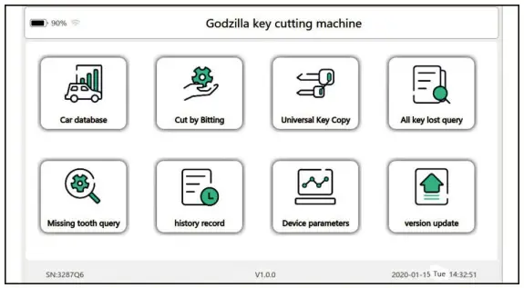
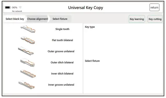

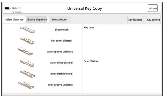
Universal Key Copy
- Click “General Key Copy” to enter the general key copy interface.
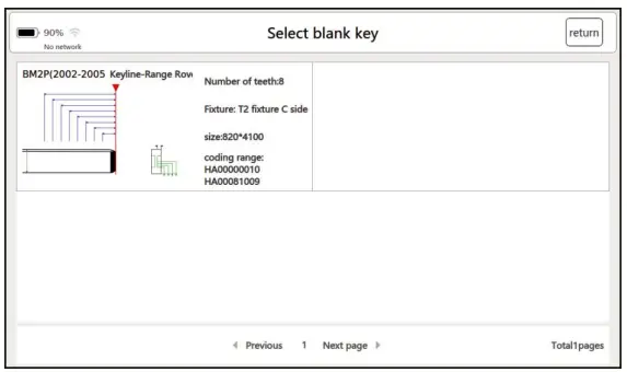
- Click the “Select Blank Key” button and click to go to the next page.
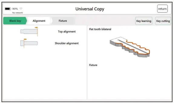
- Select the alignment method and proceed to the next page.
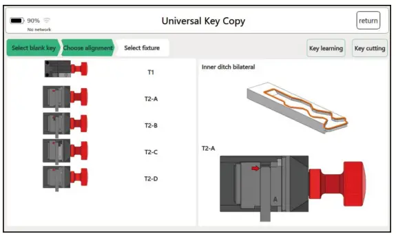
- Select the correct fixture and click “Key Learning”.
- Obtain the original key tooth code. After confirmed correct, click “Key Cut”.
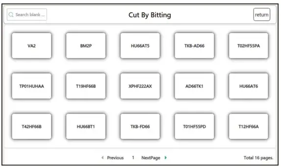
Cut By Bitting
There are two ways for using Cut By Bitting according to whether the original key is available.
The First way
There are two ways to obtain the tooth code without the original car key:
1. Get the number of teeth with a special tools.
2. Disassemble the car lock, check the lock plate to get the tooth number.
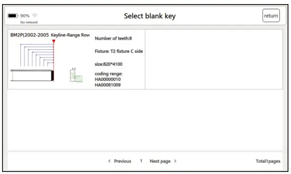
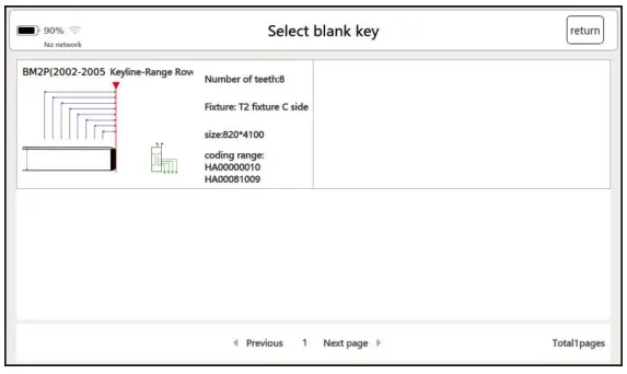
- Click “Cut By Bitting” to enter the key embryo selection interface.

- Select the key type to enter the processing page.
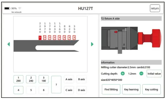
- Check the relevant parameters according to the page prompts, confirm the type of fixture and adjust the position of the fixture.
- Enter the known tooth profile number, click “Key Cut” after confirming.


The second way
There are original car keys, keys are made by Cut By Bitting.
- Click “Cut By Bitting”, select or enter the key
- Select the key type and click to enter the processing interface.
- Click “Key Learning” to get the original key tooth shape.
- After confirming, click “Key cutting”.
All Key Lost Query
- Click “All Key Lost Query” to enter the vehicle brand selection interface.
- Click on the selected vehicle brand, enter the key tooth code, and click “Query”.
- Select the key serial number from the list and click to enter the processing page.
- The tooth code will be generated automatically.
- After confirming no error, click “Key Cutting” to start processing.


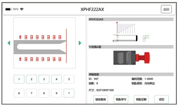
Missing Tooth Query
- Click “missing query” to enter the vehicle brand or model selection interface.
- Select or enter the vehicle brand or model and click to enter.
- Select the key embryo type and click to enter.
- Enter the known tooth shape code. If the tooth shape code is not clear, enter “?” directly, and click “missing tooth query” after input.According to the system calculated tooth shape to code and process


Onlineupgrade
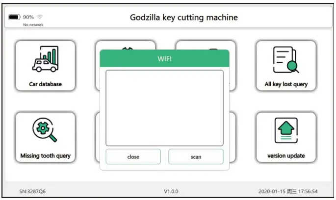
Wi-Ficonnection
- On the “Main Interface” or “Version Update” interface, click the WIFI logo
 to enter the WIFI connection interface.
 - Follow the interface prompts to connect. If it is connected, the WIFI mark as .

Software online upgrade
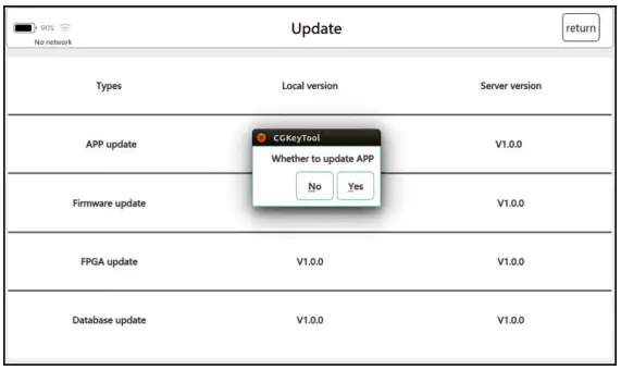
- On the main interface, click ” Version Update”.
- If the server version need update, the text will turn red, if not, it is the latest version.

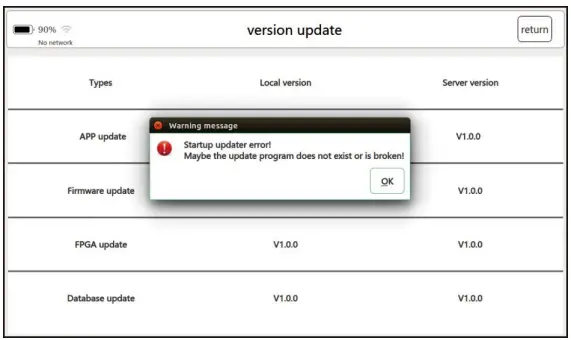
- Click “APP Update” and click “Yes” in the pop-up dialog box to download and install the latest version.

- If prompted as above shown when updated fails, you can update again after restarting.
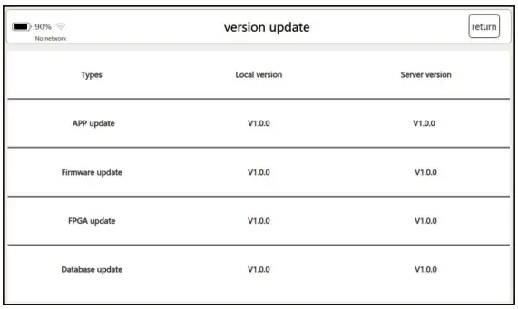
Firmware upgrade online
- On the main interface, click “Update Version”.
- If the server version update, the text will turn red, if not, it is the latest version.
- Click “Firmware Update” and click “Yes” in the pop-up dialog box to download and install the latest version.
- After completed upgrade the firmware, restarts the machine to apply the update.
Database online upgrade
- On the main interface, click “Update Version”.
- If the server version update, the text will turn red, if not, it is the latest version.
- Click “Database Update” and click “Yes” in the pop-up dialog box.
- Wait for the device offline data packet download to complete.
- After the database is updated successfully, click “OK” to complete the upgrade.
Maintenance
Maintenance instructions
The following explains how to maintain the equipment and the necessary precautions.
![]()
Using a soft cloth or a mild glass cleaner to clean the LCD touchscreen.
![]() Do not use abrasive cleaners or detergents on the touch screen and all parts of the machine.
Do not use abrasive cleaners or detergents on the touch screen and all parts of the machine.
![]() Dry your hands before using the screen. If the touch screen times overtime, or if you tap the screen with a wet finger, it may affect the touch sensitivity.
Dry your hands before using the screen. If the touch screen times overtime, or if you tap the screen with a wet finger, it may affect the touch sensitivity.
![]() Keep the key cutting and processing area clean, otherwise debris and impurities will corrode the machine parts and reduce the accuracy of key processing.
Keep the key cutting and processing area clean, otherwise debris and impurities will corrode the machine parts and reduce the accuracy of key processing.
![]() Do not wash the machine and its components directly with water, and do not use a damp cloth to wipe the machine to prevent the machine from leaking electricity or rusting metal parts.
Do not wash the machine and its components directly with water, and do not use a damp cloth to wipe the machine to prevent the machine from leaking electricity or rusting metal parts.
![]() Do not drop the equipment or subject it to severe impact.
Do not drop the equipment or subject it to severe impact.
![]() Do not replace the battery yourself or use a charger that is not included in the package.
Do not replace the battery yourself or use a charger that is not included in the package.


