DEWALT PFM3613012 Push In Thread Coupler
GENERAL INFORMATION
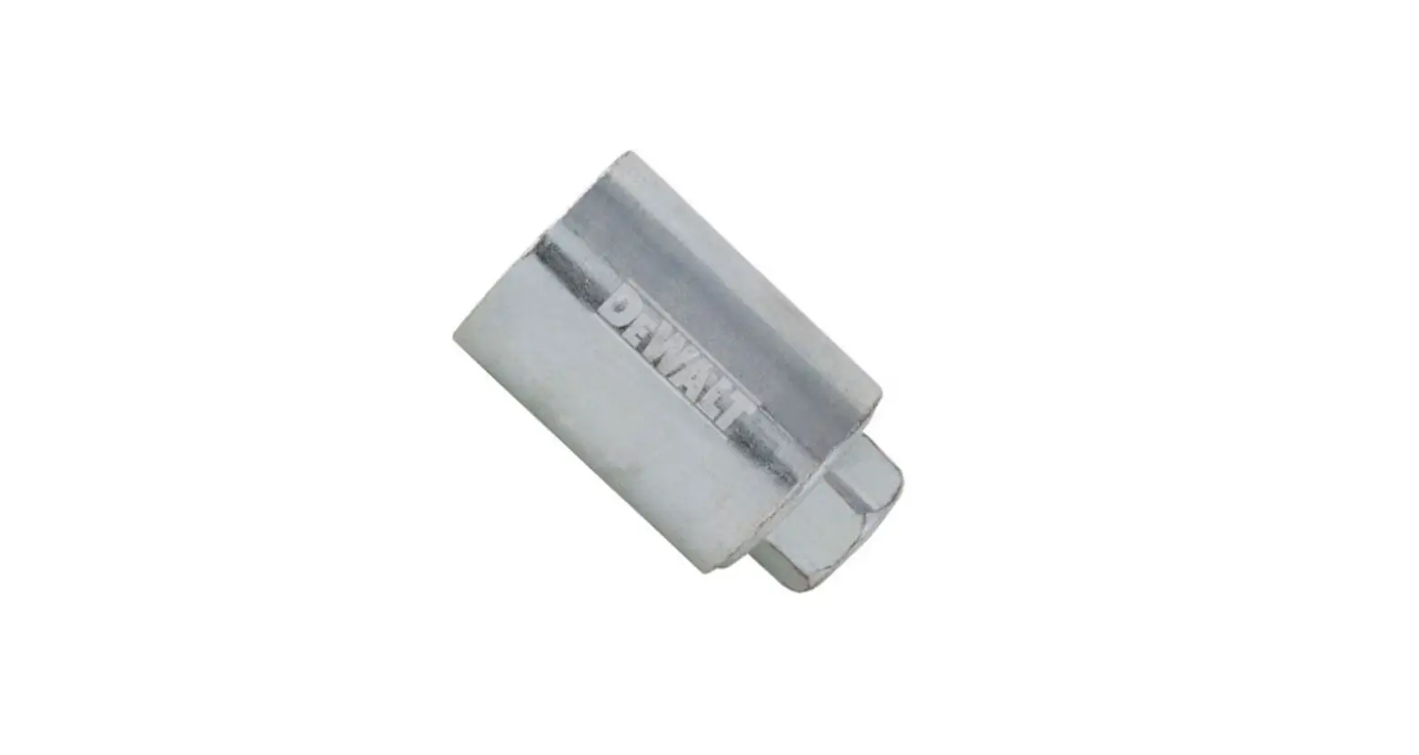
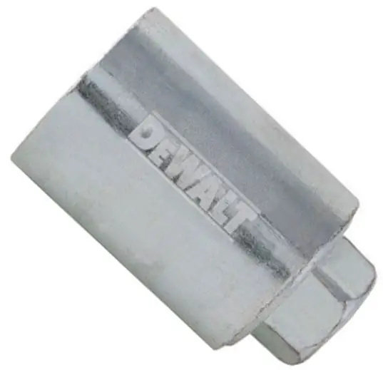
PUSH-IN THREAD COUPLER
Steel-to-Steel Threaded Connections
PRODUCT DESCRIPTION
Push-In Thread Couplers have one end that does not require turning threaded rod elements for placement during installation. These high-performance couplings can be ideal for applications such as mounting prefabricated hardware and hanger assemblies.
GENERAL APPLICATIONS AND USES
- Rod Hangers and Supports
- Prefabrication Connections
- Trapeze Assemblies
- Threaded Rod Extensions
- Cast-In Inserts and Anchors
- Distribution Systems / Utility Lines
- Replacement for Typical Rod Coupling Nuts
FEATURES AND BENEFITS
- Push-In thread does not require turning threaded rod elements during installation
- Cinch nut mechanism designed to eliminate thread misalignment
- Threaded rod compatibility can accept burred or oiled common standard UNC threaded rods
- Separate thread-in and push-in connection ends are designed for attaching existing anchor points to pre-fabrication assemblies
- Hex nut side enables installation with a wrench for the threaded end
- Couplers compatible with 3/8″-16 or 1/2″-13 UNC threads (threaded rods and bolts)
APPROVALS AND LISTINGS
- International Code Council, Evaluation Service (ICC-ES), ESL-1485 for steel threaded connections
- Code compliant with the 2021 IBC/IRC, 2018 IBC/IRC, 2015 IBC/IRC, and 2012 IBC/IRC
- Tested in accordance with ASTM F606/606M for static loading and in accordance with ACI 355.2/ASTM E488 and ICC-ES AC193 for seismic loading
GUIDE SPECIFICATIONS
CSI Divisions:
05 05 23 – Metal Fastenings. Couplers shall be Push-In Thread Couplers as supplied by DEWALT, Towson, MD. Anchors shall be installed in accordance with published instructions and the Authority Having Jurisdiction.
ANCHOR MATERIALS
- Zinc Plated Carbon Steel Body
ROD/ANCHOR SIZE RANGE (TYP.)
- 3/8″ to 3/8″ (UNC)
- 1/2″ to 1/2″ (UNC)
INSERT VERSIONS
- Single Push-In Thread
SUITABLE BASE MATERIALS
- Steel Threaded Connections
MATERIAL SPECIFICATIONS
Push-In Coupler
| Push-In Coupler | |
| Anchor Component | Component Material |
| Coupler body | Carbon steel |
| Zinc Plating | AsTM b633 (Fe/Zn5) Min. plating requirements for mild service condition |
Material Properties for Common Threaded Rods
| Description | Steel Specification (ASTM) | Threaded Rod Diameter (inch) | Minimum Yield Strength, fy (ksi) | Minimum Ultimate Strength, fu (ksi) |
| standard Carbon steel | A36 | 3/8 or 1/2 | 36.0 | 58.0 |
| High strength Carbon steel | A193, Grade b7 | 3/8 or 1/2 | 105.0 | 125.0 |
| Couplers may be considered for use in conjunction with all grades of continuously threaded carbon steels (all-thread or threaded bolts) that comply with code reference standards and that have thread characteristics comparable with ANsI b1.1 UNC Coarse Thread series. | ||||
INSTALLATION SPECIFICATIONS
Installation Specifications for Push-In Thread Coupler
| Nominal Size | Internal Thread Diameter Size | Approximate Push-In Rod Length | Approximate Outside Diameter | Approximate Length | Hex Nut Size |
| 3/8″ | 3/8″-16 (both ends) | 7/8″ | 1/2″ | 1-9/16″ | 1/2″ |
| 1/2″ | 1/2″-13 (both ends) | 1″ | 21/32″ | 1-13/16″ | 3/4″ |
INSTALLATION INSTRUCTIONS
Installation Instructions for Push-In Thread Coupler
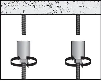
HEX NUT SIDE UP / PUSH-IN SIDE DOWN:
- Step 1
Thread couplers onto hanging rod
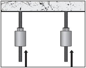
- Step 2
Push assembly into couplers
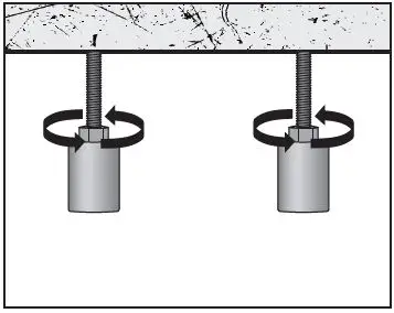
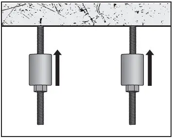
PUSH-IN SIDE UP / HEX NUT SIDE DOWN:
- Step 1
Thread couplers onto assembly
- Step 2
Push couplers (attached to assembly) into hanging rod
REFERENCE DATA (ASD)
Ultimate and Allowable Load Capacities for Push-In Thread Couplers1,2,3,4
| Ultimate and Allowable Load Capacities for Push-In Thread Couplers1,2,3,4 | ||
| Threaded Rod/Anchor Diameter in. | Tension | |
| Ultimate lbs. (kN) | Allowable lbs. (kN) | |
| 3/8 | 12,375 (55.1) | 4,125 (18.4) |
| 1/2 | 18,000 (80.1) | 6,000 (26.7) |
| 1. Allowable load capacities are calculated using an applied safety factor of 3.0 2. The tabulated allowable load capacities must be checked against the steel strength of the corresponding steel threaded insert, the lowest load level controls. 3. Allowable load capacities for 3/8-inch-diameter couplers may also be used for seismic tension loading provided the allowable values are reduced by 15 percent. 4. Allowable load capacities for the 1/2-inch-diameter couplers may also be used for seismic tension loading with no additional reduction. | ||
Allowable Loads Based on Steel Strength for Common Threaded rods1,2
| Allowable Loads Based on Steel Strength for Common Threaded rods1,2 | ||||
| Rod Diameter in. | Tension, lbs. | |||
| ASTM A36, ASTM F1554 Grade 36 Fu = 58 ksi | ASTM A307 Fu = 60 ksi | ISO 898 Class 5.8 Fu = 72.5 ksi | ASTM A193 Grade B7 Fu = 125 ksi | |
| 3/8 | 2,115 | 2,185 | 2,640 | 4,555 |
| 1/2 | 3,755 | 3,885 | 4,700 | 8,100 |
| For sI: 1 inch = 25.4 mm; 1 lbf = 0.0044 kN, 1 ksi = 6.894 MPa. 1. Allowable load used in the design must be the lesser of internally threaded coupler values and tabulated steel threaded insert values. 2. Allowable loads for steel strength are calculated using allowable tension equal to 0.33 x Fu x Anom. | ||||
ORDERING INFORMATION
Push-In Thread Couplers
| Push-In Thread Couplers | |||
| Cat. No. | Description | Internal Thread Diameter | Pack Qty. |
| PFM3613038 | 3/8″-16 Coupler Push-In | 3/8″ to 3/8″ | 20 |
| PFM3613012 | 1/2″-13 Coupler Push-In | 1/2″ to 1/2″ | 20 |


