![]() DOC1003077
DOC1003077
Operation Manual
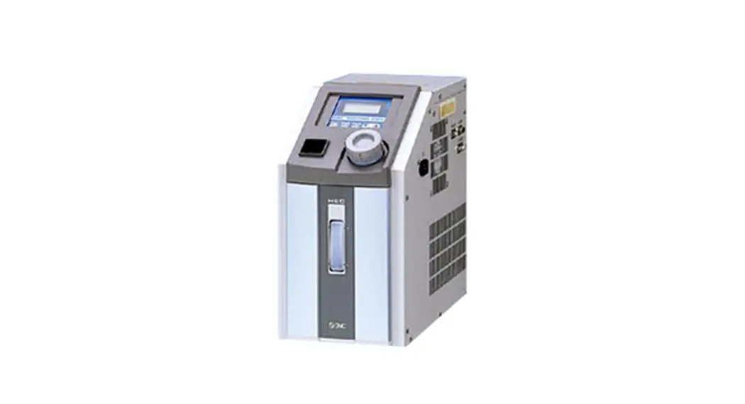
Air Cooled Thermo-con (Compact type)
HEF Series
Read Before Using
Thank you for purchasing SMC’s Thermo-con (hereinafter referred to as the “product”). This “Operation Manual” (hereinafter referred to as “this manual”) briefly explains the essential safety instruction procedures to start and stop the product and reset its alarms. Read this manual before using.
Safety Instructions
This manual contains essential information for the protection of users and others from possible injury and/or equipment damage.
- Read this manual before using the product, to ensure correct handling, and read the manuals of related apparatus before use.
- Keep this manual in a safe place for future reference.
- These instructions indicate the level of potential hazard by label of “Caution”, “Warning” or “Danger”, followed by important safety information which must be carefully followed.
- To ensure safety of personnel and equipment the safety instructions in this manual and the product catalogue must be observed, along with other relevant safety practices.
| Caution | If instructions are not followed there is a possibility of injury or equipment damage. | |
| Warning | If instructions are not followed there is a possibility of serious injury or loss of life. | |
| Danger | In extreme conditions, there is a possibility of serious injury or loss of life. |
- This manual provides the following symbols in addition to “Danger”, “Warning”, and “Caution” to present warning details in an easy-to- understand manner.
 | This symbol warns you of potential electrical shock. |
| This symbol warns you of potential burns. |
![]() Danger
Danger
- During operation or maintenance of the product, do not disable the interlock function of any device. Otherwise unexpected personnel injury or damage to the product may occur.
- When turning on/off the power observe the procedure. Otherwise unexpected malfunction or danger may occur.
- When maintaining, cleaning or in case of emergency, turn off the power source.
- After identifying a problem be sure to check the cause and take necessary countermeasures before turning on the power.
- The product is operated at high voltage.
![]() Warning
Warning
- The compatibility of equipment is the responsibility of the person who designs the system or decides its specifications.
Since the products specified here can be used in various operating conditions, their compatibility with the specific system must be based on specifications or after analysis and/or tests to meet specific requirements. - Only trained personnel should handle or operate the product.
Transportation, installation and maintenance of the product can be dangerous and should be done by persons who have full knowledge and experience on the product and system. Cover panels of the product should be opened only by qualified service technicians or qualified personnel. - Do not modify or reconstruct the unit.
- Do not service machinery/equipment or attempt to remove components until safety is confirmed.
Safety Instructions Continued
- Inspection and maintenance of machinery/equipment should only be performed after confirmation of safe locked-out positions.
- When equipment is to be removed, confirm the safety process as mentioned above. Switch off electrical supplies and ensure any high temperature parts have cooled to ambient temperature.
- Before machinery/equipment is re-started, ensure all safety measures are taken so the product and system can be started in a safe manner.
- Do not use this product outdoor (indoor use).
Do not use this product outside of the specifications. Contact SMC if it is to be used in any of the following conditions.- Conditions and environments beyond the given specifications.
- Installations in conjunction with atomic energy, railway, air navigation, vehicles, medical equipment, food and beverage, recreation equipment, emergency stop circuits, press applications, or safety equipment.
If abnormal conditions occur, such as abnormal noise or smoke, or water leakage, take the following actions.- Shut down power.
- Contact an authorised SMC dealer for repair.
![]() Caution
Caution
- After shutting down the power supply, ensure a time interval at least 3sec between ON and OFF. Restarting the product within that interval may cause it to malfunction.
- Do not use devices that generate electromagnetic radiation such as cellular phones near the product. There is a possibility that this can cause the product to malfunction.
- This unit has several interlock functions, which activate when a dangerous operation or condition occurs to stop the product and make it safe. This is a function to protect personnel and restrict operation that may cause damage to the product or facility, and to remove dangers related to safety.
- When dispose the product, contact an industrial waste disposal company for disposal of the product. To minimize the risk, drain the fluid from the product when it is scrapped. If the fluid is left inside, an accident and amage can result during transportation.
- When the circulating fluid temperature is low, do not operate it at a low flow rate. It may freeze circulating fluid in the product when used at low temperature and low flow rate.
- This unit does not use parts that meet the SCCR specifications.
Specifications
3.1 General Description and Intended Use
This product uses a built in pump to circulate liquid (water or 20% EG) at a constant temperature, controlled by Thermo-Electric (Peltier) Modules. This circulating fluid cools parts of the customer’s machine that generates heat.
3.2 General Specifications
| Item | Spec. |
| Operation temp. range | 10.0 to 60.0 °C (No dew condensation) |
| Ambient environment | Temperature: 10 to 35 °C Humidity : 35 to 70%RH Altitude : up to 2000m Environment : No corrosive gas, solvent such as thinner and flammable gas |
| Storage environment | Temperature :-40 to 70 °C (No dew condensation and icing) Humidity : 5 to 95%RH Environment : No corrosive gas, solvent such as thinner and flammable gas |
| Accuracy related to temp | Stability: +/- 0.1 °C (Circulating fluid OUT is directly connected with IN) |
| Cooling capacity | Approx. 220W (Flow rate 1L/min, set temperature 25°C and ambient temperature 25°C) |
| Circulating fluid | Water, Ethylene glycol solution up to 20% |
| Tank capacity | Approx. 110mL |
| Pump capacity | Refer to performance chart. |
| Port size | IN/OUT: Rc1/4 |
| Wetted materials | Stainless steel, EPDM, NBR, Ceramic, PPE, PPS, Carbon, PP, POM |
| Power supply | DC24V+/-10% |
| Current consumption | 12.5A (Peak current 18A) |
| Insulation resistance | 50MW or more (DC500V) |
| Over voltage category | Category I |
| Pollution degree | Pollution degree II |
| Limitation of hazardous substance | RoHS compliant products |
| Acoustic noise | 45 to 60dBA (variable fan speed control) |
| Cooling method | Air cooled |
| Main functions | Offset function, Setting value memory function, Communication, RUN/STOP input signal, Output shut off alarm, Fan speed control |
| Input operation and indications RUN/STOP input signal Output shut off alarm | Key switch / LCD display RUN/STOP input signal Circuit voltage: Approx.DC5V, Passing current: Approx.DV10mA Relay contact specification for output shut off alarm DC30V, 1A (Resistance load) |
| Communications | RS-232C / RS-485 Communications: Reading of measured temperature, Setting and reading of target temperature, Setting and reading of offset value, Storage of set value, Setting and reading of control mode. For operation by communication, it is necessary to order “Communication Manual”. Use shielded cable for serial communications. |
| Item | Spec. |
| Mass (at dry) | Approx. 3.5kg |
| Option | NPT fitting: Fluid IN/OUT fitting High head pump |
| Contents of package | Thermo-con 1pc Operation Manual 1pc Power supply cable (1m, 16AWG, with Ferrite core) 1pc |
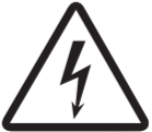
3.3 Performance Charts
Values on the performance charts are not guaranteed values but representative values. Allow margins for safety when selecting the model
3.3.1 Cooling Capacity
*Cooling capacity decrease approx. 20W when high pressure pump option selected
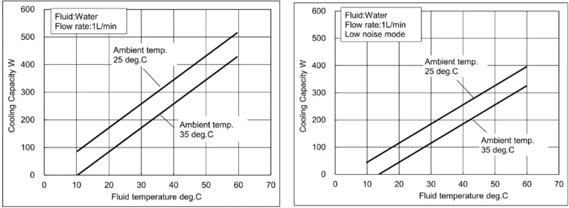
3.3.2 Heating Capacity
*Heating capacity increase approx. 10W when high pressure pump option selected
3.3.3 Pump Capacity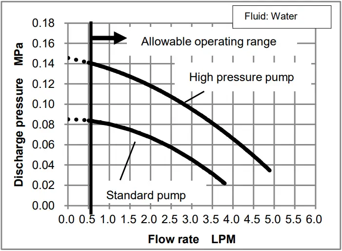
3.4 Connector Specifications
| Description | No. | Signal | Style and Part No. |
| Power supply connector |
1 |
DC24V+ | 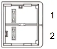 J.S.T. Mfg. JFA connector J4000 series J.S.T. Mfg. JFA connector J4000 seriesSC02B-J42SK-GHXR |
|
2 |
DC24V- | ||
| Alarm, RUN/STOP, Communication connector Note: Always use shielded cable connected to this connector. | 1 | RS-485 BUS + | 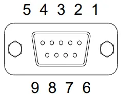 D-sub 9 pin (socket type) Fixed screw: M2.6 D-sub 9 pin (socket type) Fixed screw: M2.6 |
| 2 | RS-232C RD | ||
| 3 | RS-232C SD | ||
| 4 | RUN/STOP signal Input | ||
| 5 | SG | ||
| 6 | Output Cutoff Alarm (Open During Alarm) | ||
| 7 | Output Cutoff Alarm Common | ||
| 8 | RUN/STOP signal Input | ||
| 9 | RS-485 BUS – |
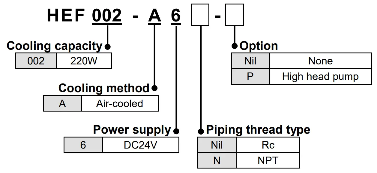
3.5 Model number of product
The product can be ordered with the model number configured as shown below.
3.6 Product serial number code
The production serial number code printed on the label indicates the year and month of production as per the following table:
| Year Month | 2022 | 2023 | 2024 | 2025 | 2026 | 2027 | …. | |
| A | B | C | D | E | F | …. | ||
| Jan | o | Ao | Bo | Co | Do | Eo | Fo | …. |
| Feb | P | AP | BP | CP | DP | EP | FP | …. |
| Mar | Q | AQ | BQ | CQ | DQ | EQ | FQ | …. |
| Apr | R | AR | BR | CR | DR | ER | FR | …. |
| May | S | AS | BS | CS | DS | ES | FS | …. |
| Jun | T | AT | BT | CT | DT | ET | FT | …. |
| Jul | U | AU | BU | CU | DU | EU | FU | …. |
| Aug | V | AV | BV | CV | DV | EV | FV | …. |
| Sep | W | AW | BW | CW | DW | EW | FW | …. |
| Oct | X | AX | BX | CX | DX | EX | FX | …. |
| Nov | y | Ay | By | Cy | Dy | Ey | Fy | …. |
| Dec | Z | AZ | BZ | CZ | DZ | EZ | FZ | …. |
Special Features
- Offset function This function controls the temperature slide by an offset value from set point temperature. When the circulating fluid travels to the target object, a certain deviation occurs between the temperature just before the object and the set temperature of the product due to the influence of ambient temperature on the piping. In this case, if the deviation is input as the offset value, the temperature of the circulating fluid just before the object can match with the setting value. For example, if 0.1 °C is set here, the actual reference temperature for control is lower than the indicated SV by 0.1 °C.
- Setting value memory function Even if the power is turned off the set values are saved and will be restored at power on.
- Output shut off alarm function The product has a self-check function that can detect faults with the product and interrupts the output to the thermo modules, pump and fan, stopping operation. This function gives an alarm if a critical error happens, the display shows ALARM. At the same time, the alarm output connector gives an output through a relay contact. This alarm cannot be removed unless the power is cycled. When the power is being cycled leave at least 3 seconds between turning the power off and turning the power back on.
- Fan speed control function Fan speed is controlled automatically in accordance with the heat load.
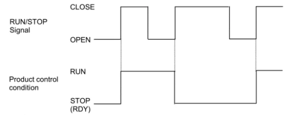
- RUN/STOP signal function by remote A contact input between pins 4 and 8 of the connector (Alarm, RUN/ STOP, Communication connector) can be used to RUN/STOP(RDY) the product.
Installation
5.1 Installation![]() Caution
Caution
- Pay special attention to the safety of all personnel when installing and transporting the product.
- Do not install the product unless the safety instructions have been read and understood.
- Leakage from the product may damage peripheral equipment. Install a drain pan under the product to capture leakage. Furthermore, mount devices like a leak sensor on the installed drain pan to detect leakage so that it can alert operators around the area.
5.2 Environment
![]() Caution
Caution
- Do not use in an environment where the product is directly exposed to water, oil, corrosive gases, chemicals, salt water or steam.
- The product should be installed upright on a stable base.
- Do not install the product in a location where the air inlet and air outlet vents are blocked. Also do not use the product in a sealed enclosure.
- Do not use in an explosive atmosphere.
- Do not mount the product in a location where it can be exposed to prolonged sunlight. Use a protective cover.
- Do not mount the product in a location where it is subject to strong vibrations and/or shock. Check the product specifications.
- Do not use the product where it can be exposed to strong electrical or magnetic emissions.
- Do not mount the product in a location where it is exposed to noise sources (such as discharging equipment, large relay and thyristor).
- Do not mount the product in a location with an altitude of more than 2000 meters.
- Do not mount the product where it is exposed to materials such as silicone, which may generate harmful gas.
- Install the product in a location where the ambient temperature range is between 10 to 35°C and the relative humidity range is between 35 to 70%. No dew condensation is allowed on the unit.
- Do not mount the product in a location exposed to radiant heat.
- To prevent adverse effects of noise on personnel, install at least 1 meters away from users.
5.3 Piping
- Ensure that the power source and the power supply of the product is turned off (or the power plug must come off )
- Ensure the flow rate of the circulating fluid is as high as possible to maintain the temperature stability. Therefore, the length of the external piping should be minimized and internal diameter should be as large as possible. Piping must have sufficient strength for the maximum discharge pressure of the circulating circuit.
- Likewise, if a tube is bent or multiple elbow fittings are used, the piping resistance will increase and the flow rate will decrease. If the flow rate falls, the temperature stability will decrease.
- If installing a tank externally, only a sealed tank should be used. Do not use an open tank.
![]() Caution
Caution
- Ensure that the INLET and OUTLET for circulating fluid is connected correctly. If any valves are used ensure that they do not restrict the flow, otherwise low flow may cause an alarm.
- When installing piping or fittings, ensure sealant material does not enter inside the port. When using seal tape, leave 1.5 to 2 threads exposed on the end of the pipe/fitting.
- Be sure to correctly tighten the fittings to the required torque(Rc1/4:12 to 14 N・m).
5.4 Wiring
- This product may use maximum current of 18A, depending on the operating conditions. Select the power source with some margins.
- Ensure that the power source and the power supply of the product is turned off before connecting the various connectors and power supply cable.
- Supply disconnecting device according to IEC60947-3 for the product must be provided in the end system.
- Do not install the disconnecting device in the place where the operation is difficult. And also the switch of the disconnecting device must comply with the direction of the switch specified by IEC60447.
- Ensure that a lock out facility is available on the power source. Ensure that an Earth Leakage Breaker with proper capacity is used. Install it above 0.6m from the floor.
- Use the dedicated power supply for this product with SELV.
- Preparation and wiring of power supply cable 1) Attach the proper connector (e.g. crimped terminal) that matches the power source to one end of accessory power supply cable. (Accessory cable: 16AWG, UL1007) 2) Connect the connector to the power source, and the product.
- Ensure that there is enough space between the power supply cable and the communication cable of the product and power cables of other equipment.
- Ensure the power supply and ground (protective earth) connections are made correctly.
- Be sure to provide the grounding (16AWG). Do not connect the ground in common with the ones for equipment that generates strong electromagnetic noise or high frequency.
- Connect the host to this unit with a twisted pair shield cable when applying communication function. When using the Communication connector, connect the circuit separated from the mains circuit by reinforced insulation.
- Ensure that external instruments connecting to this product provide the enclosure complied with UL61010-1 and use the cable which provides flame resistance (over VW-1).
5.5 Filling the product
- Ensure that the power source and the power supply of the product are turned off (or the power plug must come off).
- Remove the reservoir cap.
- If using Ethylene Glycol, refer to the suppliers Material Safety Data Sheet (MSDS) and wear Personal Protective Equipment (PPE) as appropriate.
- Fill the circulating fluid into the reservoir. Stop filling once the level of fluid reaches the “H” mark.
- Turn on the power switch to fill the piping with the fluid, then operate RUN to start the pump.
- When the piping is filled with the circulating fluid, the level of the reservoir decreases and low fluid level alarm arises accordingly. Then, turn off the power supply once again.
- Repeat the step from 4 to 6 until alarm doesn’t appear anymore.
- Then, replace the cap on the reservoir and tighten it securely.
- Keep the fluid level between H and L of the level indicator
![]() Danger
Danger
- Never touch the power switch with wet hands to avoid electrical shock.
![]() Caution
Caution
- Do not touch the surface when the set temperature is high. Temperature of the tank and the chassis near the tank could be high.
- Fluid other than water or Ethylene Glycol (up to 20%) should not be used as circulating fluid. Using such fluid may lead to leakage or damage of the pump.
- Operation of the pump with a large amount of air left in the piping for prolonged period may damage the pump. Remove air from piping before starting operation.
- If the power switch is turned on without circulating fluid, the pump could be damaged.
- Take care not to spill water over the product when supplying water to the reservoir. When a spill is made, wipe it off immediately and only supply power after it has dried. If this procedure is neglected, it may cause damage to the product.
- If a fluid with low conductivity such as DI water is used as circulating fluid, it can cause static electricity due to friction and damage the product. Take measures to minimize the static electricity from circulating fluid.
- Do not use with flow rate of circulating fluid is zero. If the flow rate is zero, the temperature of circulating fluid cannot be detected and might be increased or decreased. The pump might be broken as well.
Operation
6.1 Power Up
When power is turned on, “HELLO” is indicated on display panel for approx.
4 seconds.
6.2 Operation
The product starts up in the RDY mode (control stop) after the power is turned on, and by pressing the RUN/STOP key to put it in the RUN mode (control run), the pump, fan, and heat exchanger start operating and temperature control begins. The display shows the following information. (If the operation start status setting in the control setting mode is set to “2”, operation can be started immediately after power-on.)
6.3 Details of Controller/Display
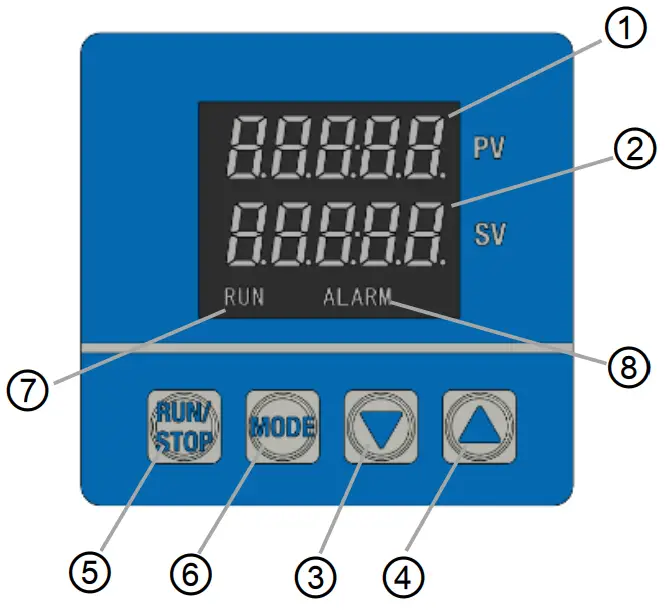
| No. | Description | Detail |
| ① | Display1 | Displays characters indicating temp. control or setting content. |
| ② | Display2 | Displays set temperature or each selected input value. |
| ③ | [▼] key (DOWN key) | Decreases set data. |
| ④ | [▲] key (UP key) | Increases set data. |
| ⑤ | [RUN/STOP] key | Used to change control mode (RUN/RDY). |
| ⑥ | [MODE] key | Used to change screens and modes. |
| ⑦ | RUN | Lights up when temp. control, pump and fan are operating(RUN). |
| ⑧ | ALARM | Lights up alarm occurs. |
6.4 Settings
Controller has two modes, Operation mode and Setting mode. Each mode has the following contents.
Operation Mode: Initial mode
Used in normal operation (e.g. setting of target temperature/offset.)
Setting Mode: Press and hold [MODE] key for 2 seconds.
Used at maintenance and initial setting for controller/PID/Communication.
Setting of functions and data in each mode
- Press [MODE] key in each mode to select the required function.
- Increase or decrease data with the [▲] or [▼] key
- Each press of the [▲] key increases the data by one count.
- Each press of the [▼] key decreases the data by one count.
- Holding the [▲] or [▼] key accelerates the increase or decrease.
Setting Mode
<SET1> Control setting mode [MODE] key
| Control Mode | |
| Heating proportional band | |
| Integral time | |
| Derivative time | |
| Heating proportional cycle | |
| ARW | |
| Cooling proportional band | |
| Cooling proportional cycle | |
| Fan Control Setting | |
| High Temp. Cutoff | |
| Low Temp. Cutoff | |
| Operation start status |
<SET2>
Communication setting mode [MODE] key
| Communication standard RS-232C / RS-485 | |
| Communication parameter | |
| Communication speed | |
| Communication address | |
| Response delay time |
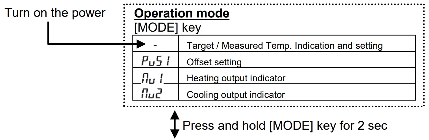
6.4.1 Operation Mode
When the power supply switch is turned on, the product is in operation mode. The target temperature is shown as well as the current measured temperature. Each presses of the [MODE] key changes the operation mode display as follows.
| No. | Modes | Function | Setting range (Min. increment) | Default |
| 1 | Target Temp./ Measured Temp. Indication and setting | Sets target temperature Set with [▲] or [▼] key | 10.0 to 60.0°C (0.1°C) | 25.0 |
| Indicates current temperature on PV and target temperature on SV | ||||
| 2 | Offset Setting | Sets the offset value of the PV. Set with [▲] or [▼] key | -9.9 to 9.9°C (0.1°C) | 0 |
| Ex. If set to 0.5, the temperature is controlled to a value that is 0.5oC lower than displayed temperature (PV). | ||||
| 3 | Heating output indicator | Indicate the heating output ratio | 0.0 to 100.0% | – |
| 4 | Cooling output indicator | Indicate the cooling output ratio | 0.0 to 100.0% | – |
6.4.2 Setting Mode
Setting mode can be shown by pressing and holding the [MODE] key for approx. 2 sec.
Pressing the [MODE] key for approx. 2 sec again will return the setting mode to the Operation mode.
Setting mode selection is indicated with ” ” and the required setting mode can be selected by increasing or decreasing the indicated number with the [▲] or [▼] key
![]()
| Function | Selects mode for each setting. Select with [▲] or [▼] key. |
| Selectable setting | 1, 2 1: Control Setting Mode 2: Communication Setting Mode |
SET1: Control Setting Mode
Selecting “01” in Setting mode “![]() ” activates the control setting mode.
” activates the control setting mode.
Each presses of the [MODE] key changes the operating mode as follows.
| No. | Modes | Function | Selectable Setting | Default |
| 1 | Control Mode Setting | Sets control mode. Select with [▲] or [▼] keys | (RUN): Temperature control and pump/fan operation enabled (RDY): Temperature control and pump/fan operation disabled | |
| 2 | Heating Proportional Band Setting | Sets the proportional band for heating. Set with [▲] or [▼] key | 0.1 to 200.0 % | 7.5% |
| This range is a percentage of temperature setting range. |
| No. | Modes | Function | Selectable Setting | Default |
| 3 | Integral Time setting | Sets the integral time. Set with [▲] or [▼] key | 0 to 3600 sec. If “0” is set, integral control is disabled. | 20sec |
| 4 | Derivative Time Setting | Sets the derivative time used for PID control. Set with [▲] or [▼] key | 0 to 3600 sec. If “0” is set, derivative control is disabled. | 0sec |
| 5 | Heating Proportional Cycle Setting | Sets heating proportional cycle. Set with [▲] or [▼] key | 0.1 to 120.0 sec If the proportional cycle is set at 1 sec. and Heating Output is 70%, the output will be 0.7 sec. ON and 0.3 sec. OFF. | 1.0sec |
| 6 | ARW Setting | Sets anti-reset wind-up. Set with [▲] or [▼] key | 0.0 to 110.0 % Reduces overshoot in PID control due to integrating operation. The integration operation is not performed above the set value. The set value must be higher than the output at stable control. | 100.0% |
| 7 | Cooling Proportional Band Setting | Sets cooling proportional band for cooling. Set with [▲] or [▼] key | 0.10 to 10.00 times. | 0.50 times of P1 set value |
| 8 | Cooling Proportional Cycle Setting | Sets cooling proportional cycle. Set with [▲] or [▼] key | 0.1 to 120.0 sec | 1.0sec |
| 9 | Fan Control Setting | Sets fan control. Select with [▲] or [▼] keys | 0 : Variable fan speed mode Fan speed controlled according to controller output volume 1 : Low noise mode Constant fan speed regardless of controller output volume |
0 |
| 10 | High Temp. Cutoff setting | Sets high temperature cutoff Set with [▲] or [▼] keys | 11.0 to 70.0°C (0.1°C) | 70.0 |
| Sets upper limit of temp measured by the internal temp sensor and stops operation of the product. | ||||
| 11 | Low Temp. Cutoff setting | Sets low temperature cutoff Set with [▲] or [▼] keys | 0.0 to 59.0°C (0.1°C) |
0.0 |
| Sets lower limit of temp measured by the internal temp sensor and stops operation of the product. | ||||
| 12 | Operation start status setting | Sets operation start status. Select with [▲] or [▼] keys | 1: Start up in the RDY mode after the power is turned on. (Temperature control and pump/fan operation disabled) 2: Start up in the RUN mode after the power is turned on. (Temperature control and pump/fan operation enabled) | 1 |
SET2: Communication Setting Mode
Selecting “02” in Setting mode “![]() ” activates the control setting mode.
” activates the control setting mode.
Each presses of the [MODE] key changes the operating mode as follows.
| No. | Modes | Function | Selectable Setting | Default |
| 1 | Communication standard setting | Sets communication standard. Select with [▲] or [▼] keys | 232C : RS-232C 485 : RS-485 | 232C |
| 2 | Communication parameter setting | Sets communication parameters Select with [▲] or [▼] keys | 1st digit : Stop bit length 1: 1 bit, 2: 2 bit 2nd digit : Parity check : None, : Odd, : Even 3rd digit : Data length 7: 7 bit, 8: 8 bit 4th digit : BCC check : Disable, : Enable The number of digits is counted from the right side. |
|
| 3 | Communication speed setting | Sets the communication speed. | 2.4 ~ 38.4 (2400 bps ~ 38400 bps) | 9.6 (9600 bps) |
| 4 | Communication address setting | Sets the communication address of the product. Set with [▲] or [▼] key | 1 to 99 addresses | 1 |
| 5 | Response delay time setting | Sets the response delay time. Set with [▲] or [▼] key | 0 to 250 ms | 0ms |
Outline Dimensions (mm)
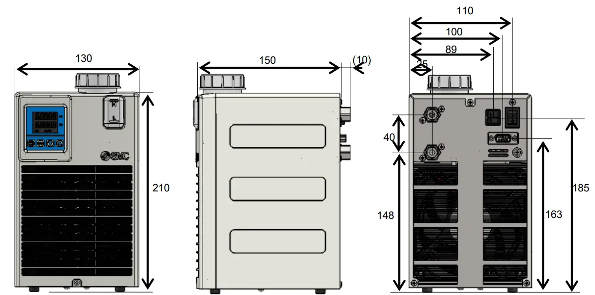
Key Parts 
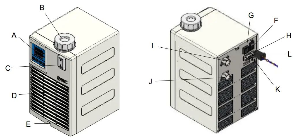
| A | Display/Operation panel | G | Power supply connector |
| B | Reservoir Cap | H | Alarm, RUN/STOP, Communication connector |
| C | Level gauge | I | Circulating fluid OUT |
| D | Air filter (air inlet) | J | Circulating fluid IN/Drain |
| E | Screw for filter maintenance | K | PE connector (M4) |
| F | Main power switch | L | Power supply cable (Accessory, with Ferrite core) |
Maintenance
9.1 Daily Check
- Indication of display panel: Check temperature condition and confirm whether or not an alarm has occurred.
- Confirm that the panel, heat sink and filter are free from dust. A large amount of dust may impair the performance.
- Confirm there is no leakage of circulating fluid and check the condition of the piping (e.g. no tight bends or crushed pipes).
- Confirm there is no abnormal sound, smell or heating from the product.
![]() Caution
Caution
- When cleaning the panel, heat sink, filter use a vacuum cleaner to remove the dust. Do not use water or steam since it leads to rusting of the frame.
9.2 General Maintenance
Replace the circulating fluid regularly to avoid any problems due to algae or contamination.
<Drain circulating fluid>
- Drain circulating fluid from the circulating fluid IN port.
Loosen the reservoir cap to help draining. (Do not remove the cap) - To drain from the piping, blow air (0.05MPa, about 1 minute) from the circulating fluid OUT to IN port. Close the reservoir cap while blowing.
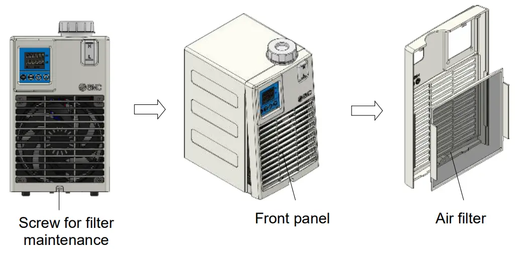
Clean air filter periodically to avoid declining performance.
<Clean air filter>
- Make sure that power is not supplied (or that the power plug is disconnected).
- Remove the filter maintenance screw (1 place), the front panel, then the air filter.
- After cleaning the filter, return it to the product.
Troubleshooting
10.1 Alarm list
| Display | Content of alarm | Product Status | Reset |
| AL0 | Memory error Occurs when the data stored inside of the EEPROM breaks. | Temp.control pump and fan stop | Turn ON Main power switch again |
| AL1 | Controller error Occurs when A/D conversion is not performed properly. | Temp.control pump and fan stop | Turn ON Main power switch again |
| AL2 | Temp. sensor disconnection alarm Occurs when the temperature sensor breaks. | Temp.control pump and fan stop | Turn ON Main power switch again |
| AL3 | Temp. sensor short circuit alarm Occurs when the temperature sensor is short-circuited. | Temp.control pump and fan stop | Turn ON Main power switch again |
| AL4 | High temp. alarm Internal temp. sensor value exceeds the high temp. cutoff temperature. | Temp.control pump and fan stop | Turn ON Main power switch again |
| AL5 | Low temp. alarm Internal temp. sensor value is lower than the low temp. cutoff temperature. | Temp.control pump and fan stop | Turn ON Main power switch again |
| AL6 | Low level alarm Occurs when liquid level is low | Temp.control pump and fan stop | Turn ON Main power switch again |
| AL7 | Thermostat alarm Occurs when the thermostat that detects excessive heating begins operating. | Temp.control pump and fan stop | Turn ON Main power switch again |
10.2 Troubleshooting
| Code | Cause | Countermeasure |
| AL0 | The EEPROM of Controller is broken due to high-level electric noise. | If the trouble cannot be solved even after restart, contoller need to be replaced. |
| The writing frequency to the EEPROM exceeds 0.1 million. | ||
| AL1 | The EEPROM of the controller is broken due to high-level electric noise. | If the trouble cannot be solved even after restart, contoller need to be replaced. |
| AL2 | Temperature sensor breaks. | If the trouble cannot be solved even after restart, temperature sensor need to be replaced. |
| AL3 | Temperature sensor is short-circuited | If the trouble cannot be solved even after restart, temperature sensor need to be replaced. |
| AL4 | Temp. sensor value exceeds the high temp. cutoff temperature. | Check the set value for high temp. cutoff temperature and confirm the temperature really reaches this value. | |
| Flow rate is zero. | If flow rate of circulating fluid is zero, the temperature of the fluid cannot be measured and the temperature of the fluid may increase. Ensure the circulating fluid is allowd to flow. | ||
| AL5 | Temp. sensor value is lower than the low temp. cutoff temperature. | Check the set value for low temp. cutoff temperature and confirm the temperature really reaches this value. | |
| Flow rate is zero. | If flow rate of circulating fluid is zero, the temperature of the fluid cannot be measured and the temperature of the fluid may decrease. Ensure the circulating fluid is allowd to flow. | ||
| AL6 | Level Switch | Fluid level of the tank is not enough | Rifill tank with fluid |
| Fluid is leaking | Check all fluid connections connected with the product. | ||
| AL7 | Thermostat | Flow rate is zero. | If flow rate of circulating fluid is zero, the temperature of the fluid cannot be measured and the temperature of heat exchanger or heatsink may increase. Ensure the circulating fluid is allowd to flow. |
| The pump breaks. | Check the pump operation. If the pump breaks, need to be replaced. | ||
| Ambient temperature is too high. (out of 10-35oC) | Correct the ambient temperature within the specification range. | ||
| Filter clogged | Clean the filter. | ||
| The fan breaks | Check the fan operation. If the fan breaks, need to be replaced. | ||
![]() 4-14-1, Sotokanda, Chiyoda-ku, Tokyo 101-0021 JAPAN
4-14-1, Sotokanda, Chiyoda-ku, Tokyo 101-0021 JAPAN
Tel: + 81 3 5207 8249 Fax: +81 3 5298 5362
URL https://www.smcworld.com
Note: Specifications are subject to change without prior notice and any obligation on the part of the manufacturer.
© 2022 SMC Corporation All Rights Reserved


