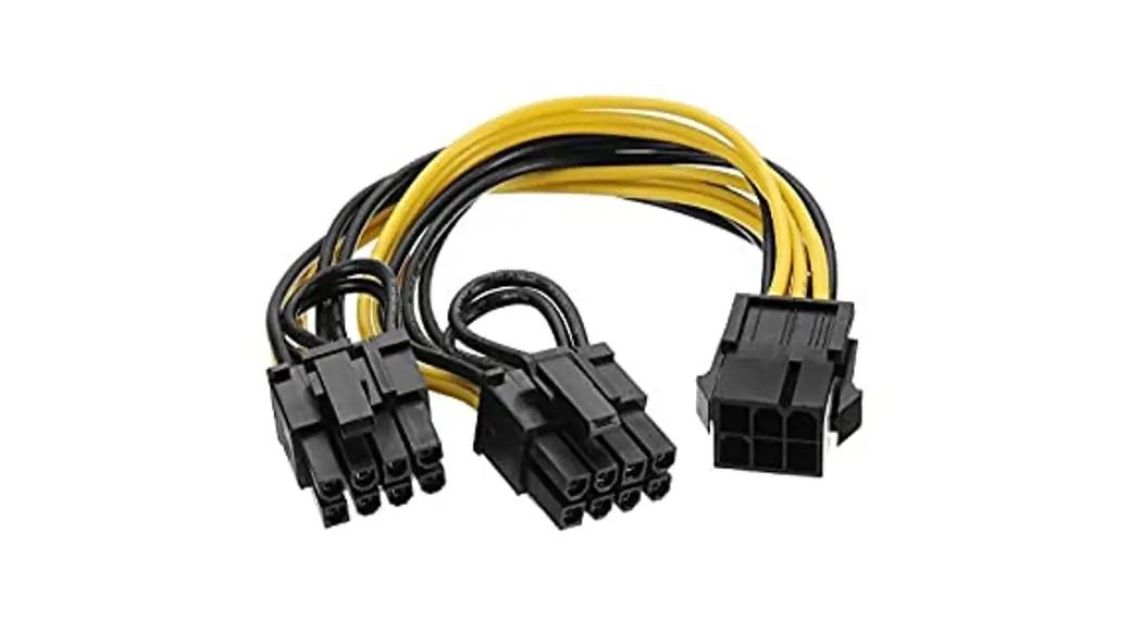
![]() VGA-PWR Graphics Card Cable
VGA-PWR Graphics Card Cable
Instruction Manual
VGA-PWR Graphics Card Cable
Revision History
| Date | Description |
| January 26, 2022 | First Release |
| April 11, 2023 | Second Release |
| April 28, 2023 | Third Release |
| May 2, 2023 | Fourth Release |
Package Contents
- 1 x 8-pin to Graphics card cable
- 1 x PS_ON# cable
- 1 x ATX PWR 4P to 4P cable
Specifications
| Model | VGA-PWR |
| Form Factor | Customized |
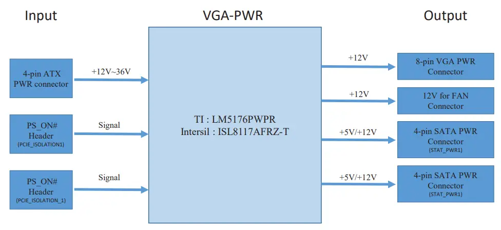
| Function | 4-pin DC_In ATX Power to output power boost up to 180W |
| Dimensions (W x L x H/mm) | 90 x 90 x 13 |
| Controller / Major IC | • TI LM5176PWPR • Intersil ISL8117AFRZ-T |
| Input Interface/Power | • 1 x 4-pin DC_In ATX Power connector • +12V~36V •1 x PS_ON# Header |
| Output connector | • 1 x 8-pin VGA Power connector • 1 x 4-pin 12V FAN connector •2 x 4-pin SATA Power connector, support 5V/12V |
| VGA Power Output | 12V/15A 300W |
| Operating Temperature | -20 ºC ~ 70 ºC |
| Storage Temperature | -40 ºC ~ 85 ºC |
Block Diagram
Mechanical Drawing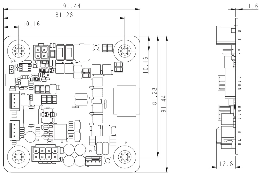 Card Layout
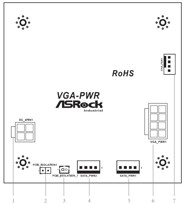
Jumpers/Header Definition
1 : 4-Pin ATX Power Connector (DC_4PIN1)
Connect Pin1 & Pin2 to MB PCIE_PWR header to provide extra 12V PCIe PWR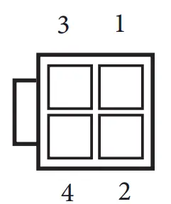
| PIN | Signal Name |
| 1 | +28VA (12V~36V) |
| 2 | +28VA (12V~36V) |
| 3 | GND |
| 4 | GND |
2. Option 1 PS_ON# Header (PCIE_ISOLATION1
Connect Pin1 & Pin2 to MB PCIE_PWR header to provide extra 12V PCIe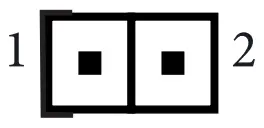 Short : PSON# Low
Open : High
3. : Option 2 PS_ON# Header (PCIE_ISOLATION_1)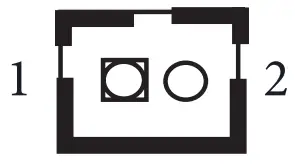 Short : Enable Low
Open : Low
4. SATA Power Connector (SATA_PWR2)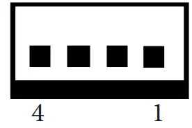
| PIN | Signal Name |
| 1 | +5V |
| 2 | GND |
| 3 | GND |
| 4 | +12V |
5. SATA Power Connector (SATA_PWR1)
| PIN | Signal Name |
| 1 | +5V |
| 2 | GND |
| 3 | GND |
| 4 | +12V |
6. VGA Power Connector (VGA_PWR1)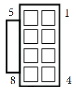
| PIN | Signal |
| 1,2,3 | +12V |
| 4,5,6,7,8 | GND |
7. FAN Power Connector (CHA_FAN1)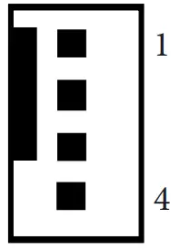
| PIN | Signal Name |
| 1 | GND |
| 2 | +12V |
| 3 | DUMMY Net |
| 4 | DUMMY Net |
![]()


