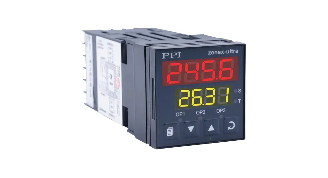
![]() Open Frame Dual Set Point Temperature Controller
Open Frame Dual Set Point Temperature Controller
Instruction Manual
This brief manual is primarily meant for quick reference to wiring connections and parameter searching. For more details on operation and application; please log on to www.ppiindia.net
INPUT / OUTPUT CONFIGURATION PARAMETERS
| Parameters | Settings (Default Value) |
| Input Type | Refer Table 1 (Default : Type K) |
| Control Logic | |
| Setpoint Low | Min. Range to Setpoint High for the selected Input type (Default : Min. Range for the ) Selected Input Type |
| Setpoint High | Setpoint Low to ax. Range M for the selected Input type (Default : Max. Range for the Selected input ) Selected Input Type |
| Offset For PV | -1999 to 9999 or -199.9 to 999.9 (Default : 0) |
| Digital Filter For PV | 0.5 to 25.0 Seconds (in steps of 0.5 Seconds) (Default : 1.0) |
| Control Output Type | |
| Output-2 Function Selection | |
| Output 2 Type |
CONTROL PARAMETERS
| Parameters | Settings (Default Value) |
| Control Mode | |
| On-Off Hysteresis | 1 to 999 or 0.1 to 99.9 (Default : 2 or 0.2) |
| Compressor Time Delay | 0 to 600 Sec. (in steps of 0.5 Sec.) (Default : 0) |
| Cycle Time | 0.5 to 120.0 Seconds (in steps of 0.5 Seconds) (Default : 20.0 Sec) |
| Proportional Band | 0.1 to 999.9 (Default : 10.0) |
| Integral Time | 0 to 1000 Seconds (Default : 100 Sec) |
| Derivative Time | 0 to 250 Seconds (Default : 25 Sec) |
OUTPUT-2 FUNCTION PARAMETERS
OP2 Function : Alarm
| Parameters | Settings (Default Value) |
| Alarm Type | |
| Alarm Inhibit | |
| Alarm Logic | |
| Alarm Timer | 5 to 250 (Default : 10) |
OP2 Function : Control
| Parameters | Settings (Default Value) |
| Hysteresis | 1 to 999 or 0.1 to 99.9 (Default : 2 or 0.2) |
| Control Logic |
OP2 Function : Blower
| Parameters | Settings (Default Value) |
| Blower / Compressor Hysteresis | 1 to 250 or 0.1 to 25.0 (Default : 2 or 0.2) |
| Blower / Compressor Time Delay | 0 to 600 Sec. (in steps of 0.5 Sec.) (Default : 0) |
SUPERVISORY PARAMETERS
| Parameters | Settings (Default Value) |
| Self-tune Command | Yes No (Default : No) |
| Overshoot Inhibit Enable / Disable | Disable Enable (Default : Disable) |
| Overshoot Inhibit Factor | (Default : 1.2) 1.0 to 2.0 |
| Setpoint Editing Permission on Operator Page | Disable Enable (Default : Enable) |
| Soak Abort Command on Operator Page | Disable Enable (Default : Enable) |
| Soak Time Adjustment on Operator Page | Disable Enable (Default : Enable) |
OPERATOR PARAMETERS
OP2 Function : Alarm
| Parameters x | Settings (Default Value) |
| Soak Start Command | |
| Soak Abort Command | |
| Soak Time | 00.05 to 60.00 M:S or 00.05 to 99.55 H:M or 1 to 999 Hours (Default : 3 or 0.3) |
| Alarm Setpoint | Minimum to Maximum Range specified for the selected Input Type (Default : 0) |
| Parameters | Settings (Default Value) |
| Alarm Deviation | -1999 to 9999 or -199.9 to 999.9 (Default : 3 or 0.3) |
| Alarm Band | 3 to 999 or 0.3 to 99.9 (Default : 3 or 0.3) |
OP2 Function : Control
| Parameters | Settings (Default Value) |
| Auxiliary Control Setpoint | (Min. Range – SP) to (Max. Range – SP) (Default : 0) |
OP2 Function : Blower
| Parameters | Settings (Default Value) |
| Blower Control Setpoint | 0.0 to 25.0 (Default : 0) |
Control Setpoint (SP) Locking
| Parameters | Settings (Default Value) |
| Setpoint Locking |
SOAK TIMER PARAMETERS
| Parameters | Settings (Default Value) |
| Soak Timer Enable | |
| Time Units | |
| Soak Time | 00.05 to 60:00 Manse 00.05 to 99:55 Hrs: Min 1 to 999 Hours (Default : 00.10 Manse) |
| Soak start Band | 0 to 9999 or 0.0 to 999.9 (Default : 5 or 0.5) |
| Holdback Strategy |
| Parameters | Settings (Default Value) |
| Hold Band | 1 to 9999 or 0.1 to 999.9 (Default : 5 or 0.5) |
| Switch-off Control Output At Timer End | |
| Power-fail Recovery Method |
| Option | What it means | Range (Min. to Max.) | Resolution |
| Type J Thermocouple | 0 to+960°C | 1 | |
| Type K Thermocouple | -200 to+1375°C | 1 | |
| 3-wire, RTD Pt100 | -199 to+600°C | 1 | |
| 3-wire, RTD Pt100 – | -199.9 to+600.0°C | 0.1 |
FRONT PANEL LAYOUT
Display Board
Small Display Version
0.39” height, 4 Digit, Upper Row
0.39” height, 4 Digit, Lower Row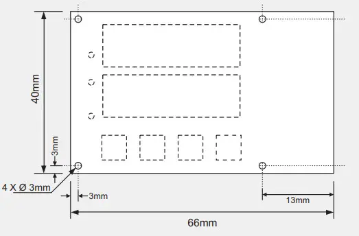 Large Display Version
0.80” height, 4 Digit, Upper Row
0.56” height, 4 Digit, Lower Row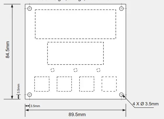 Control Board
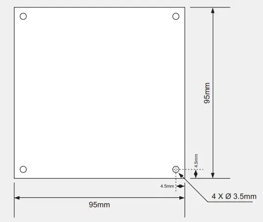 Layout
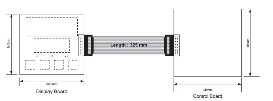 Keys Operation
| Symbol | Key | Function |
| PAGE | Press to enter or exit set-up mode. | |
| DOWN | Press to decrease the parameter value Pressing once decreases the value by one count; holding pressed speeds up the change. | |
| UP | Press to increase the parameter value Pressing once increases the value by one count; holding pressed speeds up the change. | |
| ENTER | Press to store the set parameter value and to scroll to the next parameter on the PAGE. |
PV Error Indications
| Message | PV Error Type |
| Over-range (PV above Max. Range) | |
| Under-range (PV below Min. Range) | |
| Open (Thermocouple / RTD broken) |
ELECTRICAL CONNECTIONS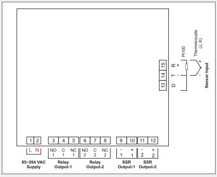
![]() 101, Diamond Industrial Estate, Namghar,
101, Diamond Industrial Estate, Namghar,
Vasai Road (E), Dist. Palghar – 401 210.
Sales : 8208199048 / 8208141446
Support : 07498799226 / 08767395333
E: [email protected],
[email protected]


