![]()
HEPS Module Quick Start Manual
SATEC Hall Effect Power Supply (HEPS) Module for Direct Current Applications
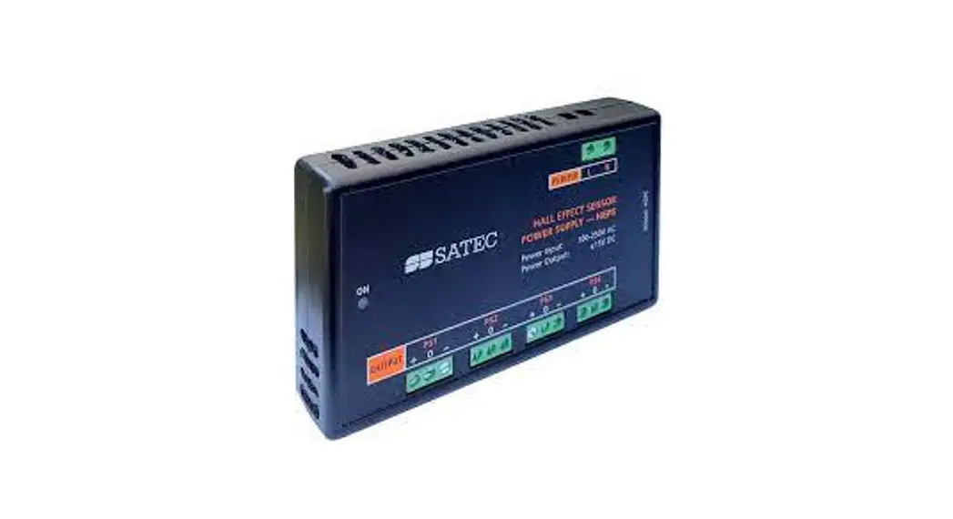
HEPS Hall Effect Power Supply Module
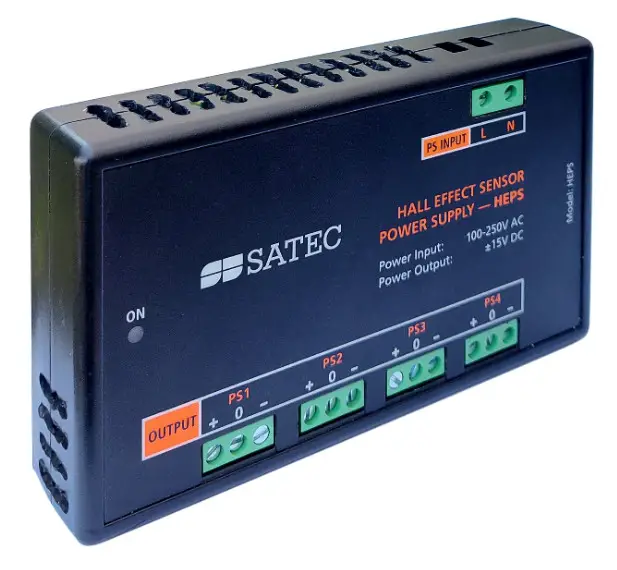
Figure 1: HEPS front plate and wiring terminals![]() Mounting, electrical connection and settings of the HEPS Module shall be made in accordance with all applicable laws and/or regulations and be performed by authorized personnel only.
Mounting, electrical connection and settings of the HEPS Module shall be made in accordance with all applicable laws and/or regulations and be performed by authorized personnel only.
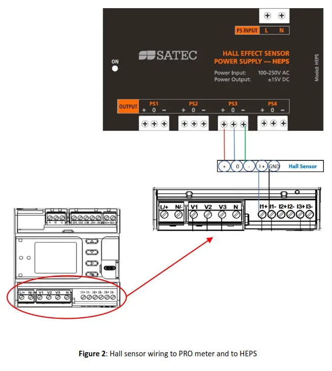
ELECTRICAL INSTALLATION
Install the HEPS module on a DIN-rail, close to an appropriate AC power supply. Wire L to phase and N to neutral current.
Each Hall Sensor must be connected to power supply via 3 wires, +, – and 0.
When using the HEPS as power supply, wire + to +, – to – and 0 to 0.
HEPS MODULE CHARACTERISTICS
- Power supply: 100-250V AC
- Output: ±15V DC
TECHNICAL SPECIFICATIONS
Input Ratings
- Voltage: 90-264V AC (50/60Hz)
- Burden: 30 VA
- Terminals: 2 X 7.5mm
- Wire Size: 1.5-0.25mm2
Output
- Voltage: ( ;-15 ;0 4 X ± 15V DC +)15 +)
- Power: 1.5W per each
Environmental
- -40°C to 60°C / -40°F to 140°F
SATEC DEVICES
SATEC products supporting DC metering and use of HEPS:
- EM235 (PRO)
- PM335 (PRO)
- PM130
- PM135
Copyright © 2021 SATEC Ltd.
www.satec-global.com
HEPS QuickStart


