AXITEC AY10786 AXIstorage Li SV2 Battery Management System
Product Information: AXIstorage Li SV2
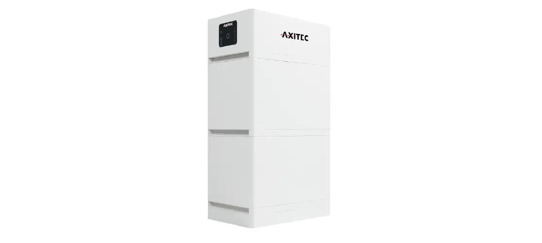
The AXIstorage Li SV2 is a high voltage Lithium-Ion Phosphate Battery storage system designed and manufactured by Axitec. It is a DC system that should only be operated by skilled and qualified personnel who have received proper training in the installation and commissioning of electrical systems and are knowledgeable about the local regulations and directives.
Features
- High voltage lithium-ion phosphate battery storage system.
- Designed for residential and commercial use.
- Capable of producing high DC power.
- Comes with safety features to prevent damage or injury.
Safety Instructions
The AXIstorage Li SV2 is a high voltage DC system that can cause lethal voltage and electric shock. Therefore, it should only be operated by skilled and qualified personnel who have received proper training in the installation and commissioning of electrical systems and are knowledgeable about the local regulations and directives. The following safety instructions should be followed:
Symbol Explanation
- Danger: Lethal voltage! Battery strings will produce HIGH DC power and can cause a lethal voltage and an electric shock. Only a qualified person can perform the wiring of the battery strings.
- Warning: Risk of battery system damage or personal injury. Do not pull out the connectors while the system is working! De-energize from all power sources and verify that there is no voltage.
- Caution: Risk of battery system failure or life cycle reduction.
Before Connecting
- Read all safety instructions carefully prior to any work and always observe them when working with the system.
- Use insulated tools when working with the system to avoid electric shock.
- Ensure that the battery system is grounded according to local regulations and directives.
- Ensure that the installation site is dry, ventilated and has sufficient space to accommodate the system.
- Do not expose the battery system to direct sunlight, high temperatures or moisture.
While Using
- Never attempt to disassemble or modify the battery system.
- Do not connect the battery system to any power source other than the one specified in the manual.
- Do not expose the battery system to water or any other liquid.
- If you notice any damage or abnormal behavior of the battery system, stop using it immediately and contact Axitec for advice and clarification.
Installation
Please refer to Annex 1: Installation and System Turn On
Progress List in the manual for detailed installation instructions.
The following general steps should be followed:
- Read all safety instructions carefully before starting the installation process.
- Ensure that the installation site is dry, ventilated and has sufficient space to accommodate the system.
- Install the battery system according to the guidelines provided in the manual.
- Connect the battery system to the power source specified in the manual.
- Turn on the battery system according to the instructions provided in Annex 1.
- Verify that the battery system is functioning correctly before use.
Debugging and Maintenance
Please refer to sections 4 (Debugging) and 5 (Maintenance) in the manual for detailed instructions on how to troubleshoot and maintain the battery system.
Shipment
Please refer to section 7 (Shipment) in the manual for information on how to prepare the battery system for shipment.
If you have any questions or concerns about the AXIstorage Li SV2, please contact Axitec immediately for advice and clarification.
Safety Instructions
The AXIstorage Li SV2 is a high voltage DC system, operated by skilled/qualified personnel only. Read all safety instructions carefully prior to any work and always observe them when working with the system.
Incorrect operation or work may cause:
- injury or death to the operator or a third party.
- damage to the system hardware and other properties belonging to the operator or a third party.
Skills of Qualified Personnel
Qualified personnel must have the following skills:
- training in the installation and commissioning of the electrical system, as well as for dealing with hazards.
- knowledge of this manual and other related documents.
- knowledge of the local regulations and directives.
Symbol explanation
 |
Danger | Lethal voltage!
|
 | Warning | Risk of battery system damage or personal injury
|
 | Caution | Risk of battery system failure or life cycle reduction. |
 | Symbol in label | Read the product and operation manual before operating the battery system! |
 | Symbol in label | General warning |
 | Symbol in label | Warning electric shock! |
 | Symbol in label | Warning against flammable substances |
 | Symbol in label | Do not reverse connect the positive and negative potential. |
 | Symbol in label | Do not place near open flame |
 | Symbol in label | Do not place in an area accessible for children and pets. |
 | Symbol in label | Recycle label. |
 | Symbol in label | Label for Waste Electrical and Electronic Equipment (WEEE) Directive (2012/19/EU) |
 | Symbol in label | Symbol of CE-conformity |
 | Symbol in label | The certificate label for Safety by TÜV SÜD. |
 | Symbol in label | The certificate label for Safety by TÜV Rheinland. |
 | Symbol in label | The certificate label for Safety by TÜV Rheinland. |
- Danger: Batteries deliver electric power, resulting in burns or fire hazard when they are short circuited, or wrongly installed.
- Danger: Lethal voltages are present at the battery terminals and cables. Severe injuries or death may occur if the cables and terminals are touched.
- Warning: DO NOT open or deform the battery module, otherwise the product will be out of warranty scope
- Warning: Whenever working on the battery, wear suitable personal protective equipment (PPE) such as rubber gloves, rubber boots and goggles.
- Warning: The AXIstorage Li SV2 system’s working temperature range: 0℃ ~50℃; Optimum temperature: 18℃~28℃. Conditions out of the working temperature range may cause the battery system over / low temperature alarm or protection which further leads to a cycle life reduction as well as it will affect the warranty terms.
- Warning: For battery installation, the installer shall refer to NFPA70 or similar local installation standard for operation.
- Caution: Improper settings or maintenance can permanently damage the battery. Caution: Incorrect inverter parameters will lead to a further faulty/damaged battery.
Reminder
- It is very important and necessary to read the user manual carefully before installing or using the battery. Not doing so or not to follow any of the instructions or warnings in this document can result in electrical shock, serious injury, or death, or can damage the battery, potentially rendering it inoperable.
- If the battery is stored for a long time, it is required to charge them every six months, and the SOC should be no less than 90%.
- Batteries need to be recharged within 12 hours, after full discharge.
- Do not expose cable outside.
Before Connecting
- After unpacking, please check the product and packing list first. If a product is damaged or if there is a lack of parts, please contact the local retailer.
- Before installation, be sure to cut off the grid power and make sure the battery is in the switched-off mode.
- Wiring must be correct, do not mistake the positive and negative cables, and ensure there is no short circuit with the external device.
- It is prohibited to connect the battery to AC power directly.
- The Battery system must be well grounded, and the resistance must be less than 100mΩ.
- Please ensured the electrical parameters of the battery system are compatible to the related equipment.
- Keep the battery away from water and fire.
While Using
- If the battery system needs to be moved or repaired, the power must be cut off and the battery is completely shut down.
- It is prohibited to connect the battery with a different type of battery.
- It is prohibited to use the batteries with a faulty or incompatible inverter.
- It is prohibited to disassemble the battery (QC tab removed or damaged).
- In case of fire, only dry powder fire extinguisher can be used, liquid fire extinguishers are prohibited.
System Introduction
Product Introduction
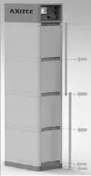
The AXIstorage Li SV2 is a high voltage battery storage system based on lithium iron phosphate batteries, which is a new energy storage product of Axitec. It can be used to provide reliable power for various types of equipment and systems. AXIstorage Li SV2 is especially suitable for those application which require high power output, limited installation space, restricted load-bearing and long cycle life.
Specifications
System parameter
| Product Type | AXIstorage Li SV2 | ||
| Cell Technology | Li-ion (LFP) | ||
| Battery System Capacity(kWh) | 7.10 | 10.65 | 14.20 |
| Battery System Voltage (Vdc) | 192 | 288 | 384 |
| Battery System Capacity (AH) | 37Ah | ||
| Battery Controller Name | BMS SV2 | ||
| Battery Module Name | Energypack SV2 | ||
| Battery Module Quantity(pcs) | 2 | 3 | 4 |
| Battery Module Capacity(kWh) | 3.552 | ||
| Battery Module Voltage (Vdc) | 96 | ||
| Battery Module Capacity (AH) | 37 | ||
| Battery System Charge Upper Voltage (Vdc) | 216 | 324 | 432 |
| Battery System Charge Current (Amps, Standard) | 7.4 | ||
| Battery System Charge Current (Amps, Normal) | 18.5 | ||
| Battery System Charge Current (Amps, Max.@15s) | 40 | ||
| Battery System Discharge Lower Voltage (Vdc) | 174 | 261 | 348 |
| Battery System Discharge Current (Amps, Standard) | 7.4 | ||
| Battery System Discharge Current (Amps, Normal) | 18.5 | ||
| Battery System Discharge Current (Amps, Max.@15s) | 40 | ||
| Short circuit rating (Amps) | <4000 | ||
| Efficiency (%) | 96 | ||
| Depth of Discharge (%) | 90 | ||
| Dimension (W*D*H, mm) | 450*296*822 | 450*296*1118 | 450*296*1414 |
| Communication | CANBUS/Modbus RTU | ||
| Protection Class | IP55 | ||
| Weight(kg) | 82 | 117 | 152 |
| Operation Temperature (℃) | 0~50℃ | ||
| Storage Temperature (℃) | -20~60℃ | ||
| Altitude(m) | <2000 | ||
| Humidity | 5~95% | ||
| Product Certificate | VDE2510-50, IEC62619, IEC62477-1, IEC62040-1, CEC, CE | ||
| Transfer Certificate | UN38.3 | ||
| Battery Controller Dimensions(W*D*H) Battery Module Dimensions (W*D*H) 3)Battery bottom base Dimensions(W*D*H) | 450×296×190 mm 450×296×296mm 450×296×40 mm | ||
Battery Module (Energypack SV2)
| Product Type | Energypack SV2 |
| Cell Technology | Li-ion (LFP) |
| Battery Module Capacity (kWh) | 3.552 |
| Battery Module Voltage (Vdc) | 96 |
| Battery Module Capacity (Ah) | 37 |
| Battery Module Serial Cell Quantity (pcs) | 30 |
| Battery Cell Voltage (Vdc) | 3.2 |
| Battery Cell Capacity (AH) | 37 |
| Dimension (W*D*H, mm) | 450*296*296 |
| Weight (kg) | 35 |
| Operation Temperature | 0~50℃ |
| Storage Temperature | -20~60℃ |
| Transfer Certificate | UN38.3 |
Control Module BMS SV2 (internal power supply)

Control Module (BMS SV2) Display Panel
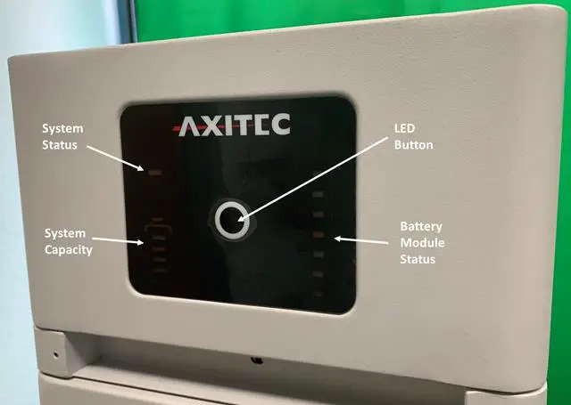
 | Short Press | activates the LED panel for 20sec. |
| Long Press (more than 5sec) | When status LED is fast flashing blue ●, release the button, then the baud rate of RS485 is 115200. | |
| When status LED is fast flashing orange ●, release the button, then the baud rate of RS485 is 9600. |
Status 2 colors, blue and orange
Refer to [LED Indicators Instructions]
Battery Module Status
 | Blue solid | Normal |
| Orange solid | Individual module alarm or protection. See trouble shooting steps in section 5.1 |
System Capacity
 System SOC
Each LED indicates 25%SOC
LED Indicator Instructions
| Condition | | | Note |
| Self-checking | Blue, Flashing | All flashing | |
| Self-checking failure | Orange, slow flashing | Off | Battery Module Status off. See trouble shooting steps in section 5.1 |
| Black start success | Blue, fast flashing | Off | |
| Black start failure | Orange, fast flashing | Off | See trouble shooting steps in section 5.1 |
| Communication Lost or BMS error | Orange, solid | Indicate SOC, blue, solid | See trouble shooting steps in section 5.1 |
| Idle | Blue, slow flashing | Indicate SOC, blue, solid | |
| Charge | Blue, solid | Indicate SOC, blue, solid | |
| Floating charge | Blue, solid | All flashing, horse race lamp | |
| Discharge | Blue, flashing | Indicate SOC, blue, solid | |
| System sleep | Blue, flashing | Off | Battery module status off |
Remark: Slow flashing: 2.0s ON/1.0s OFF; Flashing 0.5s ON/0.5s OFF; Fast flashing: 0.1s ON/0.1s OFF
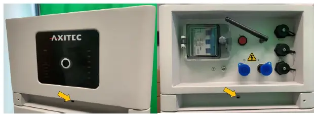
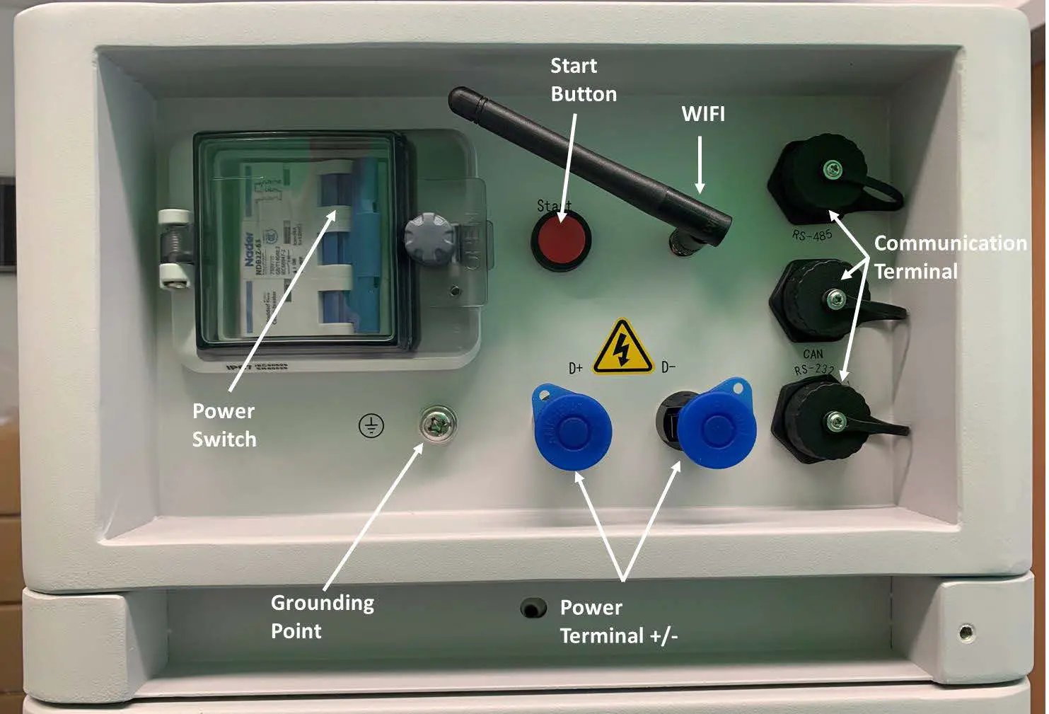
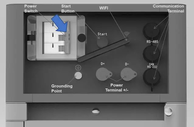
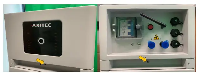
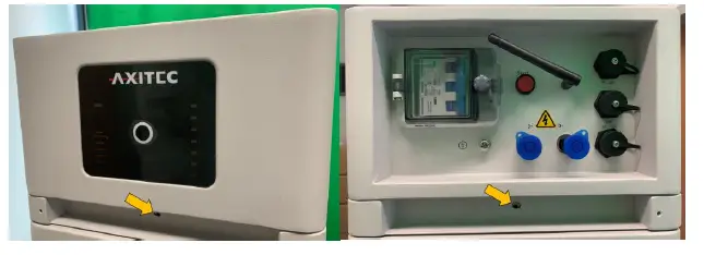
Control Module (BMS SV2) Cable Panel

Power Switch
- ON: main breaker ON, it is now possible to turn on the battery system by start button.
- OFF: system turns off completely, no power output.
- Caution: When the breaker is tripped off because of over current or short circuit, wait at least 30min before turning on again, otherwise it may cause damage to the breaker.
Start
Start function: press more than 5sec until the buzzer rings, to turn on the controller. Black start function: when the system is switched on, and the relay is OFF, press more than 10sec, and the relay will turn on for 10 min without communication (depending on conditions).
Wi-Fi
- Wireless maximum output power: 20dBm
- Operating frequency: 2412-2472MHz
- Gain of antenna: Max 3dBi
- Modulation system:
- DBPSK/DQPSK/CCK(DSSS)
- BPSK/QPSK/16QAM/64QAM(OFDM)
- Modulating Repetition:
- 1Mbps/2Mbps/5.5Mbps/11Mbps (DSSS)
- 6Mbps/9 Mbps/12 Mbps/18 Mbps/24 Mbps/36 Mbps/48 Mbps/54 Mbps (OFDM) MCS0~MCS7(802.1 1n 20MHz)
- Channel spacing:5MHZ
- Type of antenna: 2.4G IPEX-SMA Antenna
- Power Terminal (+/-)
For connecting the power cables between battery system and Inverter.
Communication Terminal (RS485 / CAN / RS232)
RS485 Communication Terminal: (RJ45 port) follow MODBUS 485 protocol, for communication between battery system and inverter.
CAN Communication Terminal: (RJ45 port) follow CAN protocol, for communication between battery system and inverter.
RS232 Communication Terminal: (RJ45 port) for manufacturer or professional engineer for debugging or service.
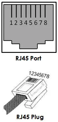
Definition of RJ45 Port Pin
| No. | CAN | RS485 | RS232 |
| 1 | — | — | — |
| 2 | GND | — | — |
| 3 | — | — | TX |
| 4 | CANH | — | — |
| 5 | CANL | — | — |
| 6 | — | — | RX |
| 7 | — | RS485A | — |
| 8 | — | RS485B | — |
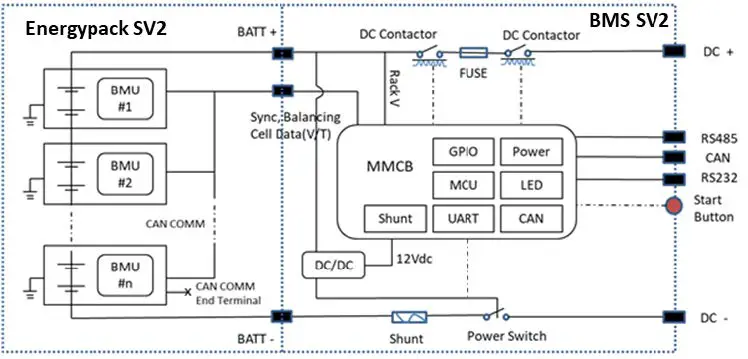
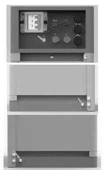
System Diagram
Installation
Required Tools
The following tools are required to install the battery pack:
 |  |  |
| Wire Cutter | Crimping Modular Plier | Cable Ties |
 |  |  |
| Screwdriver Set | Electric Screwdriver | |
 |  | |
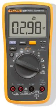
| Adjustable Wrench | Sleeve Piece | 600VDC Multimeter |
NOTE
Use properly insulated tools to prevent accidental electric shocks or short circuits.
If insulated tools are not available, cover the entire exposed metal surfaces, except their tips, with available insulated alternatives (insulating tape).
Safety Gear
It is recommended to wear the following safety gear when dealing with the battery pack

System Working Environment Check
Cleaning
Before installing and switching system power on, dust and iron scurf must be removed to keep a clean environment.
The system cannot be installed in a desert area without an enclosure to protect it from sand.
Danger: Each Battery module has active DC power at its terminal all the time, be careful when handling the modules.
Ventilation
AXIstorage Li SV2 system’s working temperature range: 0℃~50℃; Optimum temperature: 18℃~28℃.
There are no mandatory ventilation requirements for the battery modules, but please avoid installations in confined area. The aeration shall avoid high salinity, humidity or temperature. Caution: The AXIstorage Li SV2 system has IP55 protection. But please avoid frost or direct sunlight. Conditions out of the working temperature range will cause the battery systems over / low temperature alarm or protection trigger which further leads to cycle life reduction. If it is necessary due to the environment, a cooling system or heating system should be installed.
Fire-extinguisher System
It must be equipped with fire-extinguisher system for safety purpose.
The fire-extinguisher system needs to be regularly checked to be in normal condition. Refer to the using and maintenance requirements and please follow the local fire equipment guidance.
Grounding System
Before installing the battery make sure the grounding point of the basement is stable and reliable. If the battery system is installed in an independent equipment abin (e.g., container), make sure the grounding of the cabin is stable and reliable.
The resistance of the grounding system must be ≤100mΩ
Clearance
Minimum distance to heat sources is more than 2 meters. The minimum distance to another battery module(rack) is more than 0.5 meters.
Handling and Placement
Warning: The battery pile’s power terminals are under high voltage DC. It must be installed in a restricted access area.
Warning: AXIstorage Li SV2 is a high voltage DC system, operated by qualified and authorized personnel only.
Handling and Placement of the Battery Modules
A single battery module weights 36kg. Without handling tools, it must be handled by at least 2 persons.
Handling and Placement of the Base
The base is light, a single person can handle it.
Selection of Installation Sites
- The AXIstorage Li SV2 system’s working temperature range is 0℃~50℃; Optimum temperature: 18℃~28℃. Do not place the battery system in direct sunlight. It is suggested to build sunshade equipment. In cold area a heating system is required.
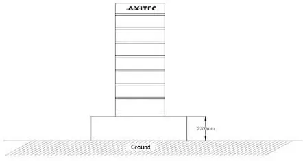
- The AXIstorage Li SV2 system shall not be places in water. The battery base cannot be placed in rain or other water sources. For outdoor installation or other water exposed locations, it is recommended to place the base module on a foundation at least 300 mm above the ground.
- The basement must bear the weight of whole battery system (130~300kg).
- The AXIstorage Li SV2 system must be installed on fixed ground.
Packing List
| BMS SV2 Battery Controller | ||
| Item | Description | Set |
| 1 | BMS SV2 Battery Controller | 1 |
| 2 | AXIstorage Li SV2 basement (450*296*40, mm) | 1 |
| 3 | EPE foam | 3 |
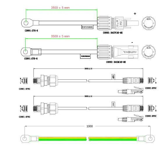
| 4 | 3.5m black external communication cable (RJ45 – M19) | 2 |
| 5 | 3.5m DC+ red external power cable (10AWG) | 1 |
| 6 | 3.5m DC- black external power cable (10AWG) | 1 |
| 7 | 1m yellow-green grounding cable (10AWG) | 1 |
| 8 | M4 screws for fixing mounting rails | 14 |
| 9 | M8 bolts for fixing basement | 4 |
| 10 | Angle for wall mount | 2 |
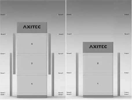
| 11 | 660 mm mounting rail For up to 2 battery modules installation | 2 |
| 12 | 622 mm mounting rail In combined use with the 660mm mounting rail for up to 4 modules installation, see installation pictures below; | 2 |
| Energypack SV2 Battery Module | ||
| 1 | Energypack SV2 battery module | 1 |
| 2 | EPE foam | 2 |
No additional kits needed for AXIstorage Li SV2 installation.
Mounting and Installation of the Base
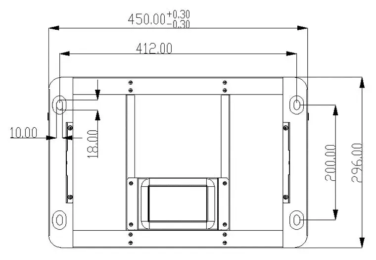
The base must be fix installed on the basement with 4pcs M8×80 foundation bolts.
Battery rack basement holes bitmap (unit: mm):
Wall Mounting
As alternative to securing via base module, the fixing of the battery system can also be realized via a wall mounting. For this purpose, the supplied brackets must be fixed to the uppermost screw connection of the metal rail and to the wall. A stable connection to the wall must be ensured for proper operation.
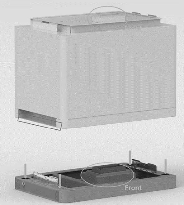
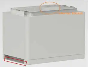
Battery Modules and Control Module (BMS) pile up
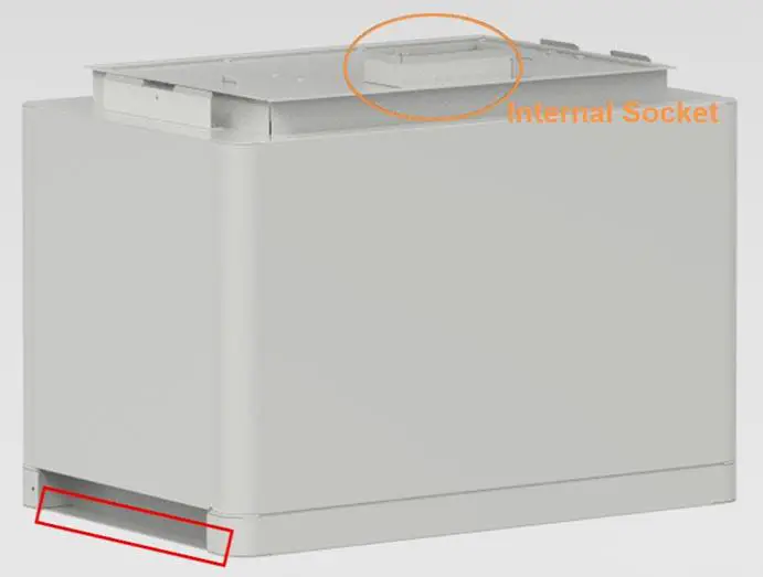
Handle the modules above the red marked edgings on both sides.
Caution: If hands are under this red marked side, hands will get hurt.
Danger: when the battery relates to the base, the internal sockets still have high voltage DC power from serial connected battery modules (battery module can’t be turned off).
Installation Metal Mounting Rails
In the control module’s package are 2 pcs short and 2 pcs long metal mounting rails. Fix these metal mounting rails at both back side corners.

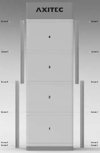
Locking of the control Module’s fix screw on left and right side
Cables Connection
Attention:
- Danger: The battery system is a high voltage DC system. Make sure the grounding is fixed and reliable.
- Danger: All the plugs and sockets of the power cables must be not reverse connected. Otherwise, it will cause personal injury.
- Danger: No short circuit or reversed connection of the battery system’s positive and negative port. Caution: Wrong communication cables connection will cause a battery system failure.
Grounding
The AXIstorage Li SV2 has three grounding points, where the grounding cable can be connected (above the right side of top metal mounting rail screw or beside both sides of the screw in the base). Connect the grounding cable to one of these grounding points.
Grounding cable must ≥10AWG. The cable shall be copper with yellow-green color.
Cables
Note: For the power cables, water-proof connectors are used.
To disconnect, a special tool is required. Do not pull out directly.
Note: For communication cable use RJ45 connector and water-proof cover(M19-RJ45) matched with controller connection port.
Connection to Inverter
Follow the installation instructions of the inverter for connecting the power cables and the communication cable to the inverter. Check the compatibility of the inverter with the storage unit. Consider the voltage range of the inverter when selecting the number of energy packs.
If the storage model must be selected when configuring the inverter, select the Force H2 storage from Pylontech.
The inverters listed in the table below are compatible with the AXIstorage Li SV2.
| Brand | Inverter Type | Firmware Version |
| Sungrow | SH5.0/6.0/8.0/10RT | SAPPHIRE-H_V11_V01_A |
| GoodWe | EH/ET/BT/BH series | V14 |
| Growatt | SPH10000TL3 | V410 |
| Solis | RHI-3P-HVES-5G series | 4002E |
| Ingeteam Power Technology | ISS 1Play 3TL / 6TL | ABH1002AA, ABH1003_Q(disp) |
| ISS 1Play 3TL M / 6TL M | ABH1007_A, ABH1003_Q(disp) | |
| Sermatec | SMT-10K/30K/50K-TL-TH | |
| Lux Power | Hybrid HB series | |
| Delios s.r.l. | DLX HV series | V3.00 |
| SolaX Power | X1/X3-Hybrid HV | |
| SolarMax | ES-T series | V3.00 |
Switch on the System
Warning: Double check all the power cables and communication cables. Make sure the voltage of the inverter/PCS is same level with the battery system before connection. Check if all the power switches are OFF.
Switch on the System Step by Step:
- Check if all cables are connected correctly. Check if the grounding is connected.
- If necessary, turn on the switch at the inverter`s battery side or between inverter and battery. If possible, turn on AC or PV power source to wake up the inverter.
- Open the protection cover of the Power switch and turn on power switch.
- Press start button for at least 5 seconds or until the buzzer rings. The battery takes 10-30s for self-checking.
If the inverter is turned on by AC or PV source, then most inverters can setup communication with the BMS automatically. In this case, the BMS will close its relay and the system is ready for work.
If the inverter needs battery power to turn on, then check the LED of the battery, it shall be:
Status: Orange, solid
SOC: blue, solid - In this case, press the Start button for at least 10s, till the Status lights blue and fast flashing, then the battery will black start to support the inverter and after the inverter turned on and set up communication, then BMS is ready for work.
- If further setup of the inverter and battery is necessary, this is done via the inverter (see 3.6 Connection to inverter).
Caution: When the breaker is tripped off because of over current or short circuit, wait for 30min to turn it on again, otherwise it may cause damage to the breaker.

Warning: If there is a failure during the self-check, you must first debug the failure and then go to the next step.
If the “STATUS” lamp shows orange from the beginning, it means that there has been some failure in the battery string. The Power relays in the BMS will open, you must debug first.
Note: The LED lamp will be off after 20sec without any operation.
Caution: During first time power on, the system will require to do full charge progress for SOC calibration purpose.
Caution: it is suggested to fully charge the whole Battery Energy Storage System (BESS) first after the installation or after long time storage without charging. Depending on the SOC level, there will be a regularly (3 month) full charge requested during continuous operation as well. It will be handled automatically by the communication between BESS and the external device.
Switch off the System
When a failure occurs or before service, you must turn the battery storage system off:
- Turn off the inverter or power supply on the DC side.
- Turn off the switch between PCS and battery system.
- Turn off the “Power Switch” of the BMS.
Caution: Before replacing the battery module for service, charge/discharge the existing battery modules until its voltage is like the voltage of the replacement. Otherwise, the system needs long time to do the balancing for this replaced battery module.
Online Monitoring
Online monitoring is possible via the SOLARMAN platform. For easier monitoring of the system status and further information in case of problems, online registration of the storage system is recommended. A WLAN connection must be available for this. Monitoring is possible both with the computer (https://home.solarmanpv.com/login) and with the smartphone (SOLARMAN Smart, Apple App Store and Google Play). The setup must be performed via the app. Instructions for the setup can be found in the download area of our website: Axitecsolar.com
The installation is not necessary for operating of the system.
Debugging
This system debug is for the Battery Energy Storage System (BESS). The system can’t do the debug itself. It must be operated with configured inverter, UPS, PCS and EMS system together.
| Debug Step | Content |
| Preparation of debug. | Turn on the BESS, refer to chapter 3. Before turning on the whole BESS, turning on the load is not allowed! Remark: Except the BESS, if other equipment has its own system turn on steps, follow the operation manual. |
| Working together with inverter |
|
Maintenance
Troubleshooting:
Danger: The AXIstorage Li SV2 is a high voltage DC system, operated by qualified and authorized persons only.
Danger: Before checking the failure, check all cable connections and if the BESS can turn on normally or not.
Check the surroundings first
| No | Problem | Possible Reason | Solution |
| 1 | No power output, no LED on. | Start button pressed too short. | To turn on, push the button for at least 5s To black start, push the button for at least 10s. |
| The button battery in the controller is missing or defective. The power supply of the controller is in failure | Change the controller module. | ||
| The battery voltage is too low. | Make sure there are at least 2 battery modules. | ||
| The connector of the base is in failure | The base is not connected or needed to change the base | ||
| 2 | After turned on, status LED is slowly flashing orange. Others are off. | Self-checking failure. DC side has a voltage, but the voltage difference with the battery system is higher than 20V. | Make sure there is no DC voltage or set correct DC voltage before press start button. Then follow turn on process. |
| BMS internal failure. | Use debug tool to further analysis or change the controller module. | ||
| 3 | Status LED is fast flashing orange, others are off. | The time interval after the last black start is too short. | Wait more than 5 minutes and try to black start again. |
| The battery system is under error condition such as: temperature or current protection or other error, thus it does not response black start. | Make sure there is no other protection factor. Or use the debug tool for further analysis. | ||
| 4 | Buzzer rings permanently | Relay adhesion or failure. | Completely disconnect the battery system from any DC source, then do a restart. If the problem remains, swap the controller. |
| 5 | Status LED solid orange. Battery module LED blue solid. | Communication lost with inverter | Check the communication cable PIN and wiring whether it is correct. |
| Over current protection. | Check DC side. Wait until BMS releases protection. | ||
| Controller failure. | Use the debug tool for further analysis or change the controller module. | ||
| 6 | Status LED solid orange. Battery module exists and LED is orange solid | Over/ under temperature protection. | Check environment temperature. Wait until the BMS releases. |
| Over voltage protection. | Check DC charge voltage setting. Wait until the BMS releases. | ||
| Under voltage protection. | Use black start function and then charge the system. | ||
| Battery module BMS failure | Use debug tool for further analysis or change the battery module. | ||
| 7 | All LEDs light blue but there is no output. | Fuse triggered | Change the controller module |
| 8 | Other failure | Cell failure or electrical board failure. Failure needs debug tool for further debugging. | If you can’t find out failure point or can’t check, please contact distributor or Axitec. |
Once a certain failure is detected following the trouble shooting steps, shut down the battery string first before replacement to avoid further over discharge to the system due to self-consumption.
Replacement of main components
Danger: The AXIstorage Li SV2 is a high voltage DC system, operated by qualified and authorized persons only.
Danger: Before replacing a main component, shut down the maintenance battery string’s power. Check that the D+ and D- terminals are without power. For the turn off progress refer to chapter 3.6.5.
Replacement of Battery Module
Charge existing modules to the charge level of the new module (new module fully charged from factory).
Turn off the whole battery string’s power. Make sure the D+ and D- terminals are without power. For the turn off progress refer to chapter 3.5.4.
Dismantle D+ and D- Power Cable, Communication Cable and Grounding Cable.
Dismantle the control Module’s fix screws of left and right side. And dismantle the fix metal mounting rails.
Move the control module and each battery module one by one.
Danger: when battery relates to the base, the internal sockets still have high voltage DC power from serial connected battery modules (battery module can’t be turned off).

Handle above the red marked edgings on both sides of the battery modules and control module (BMS).
Caution: If hands are under this red marked side, hands will get hurt.
Warning: A single battery module weights 35kg. Without handling tools at least 2 persons are needed to handle it.
Pile up the new battery module. And pile up the battery modules and control module again.
Install back the control module’s fix screw on the left and right side and install back the fix metal mounting rails.
Install back the grounding Cable, Communication Cable and the D+ and D- Power Cables.
Turn on the battery string. Refer to chapter 3.5.3.
Replacement of Control Module (BMS)
Turn off the whole battery string’s power. Make sure the D+ and D- terminals are without power. For the turn off progress refer to chapter 3.5.4.
Dismantle D+ and D- Power Cables, Communication Cable and Grounding Cable.
Dismantle the control Module’s fix screw on the left and right side and dismantle the fix metal mounting rails.
Remove the control module.
Danger: when battery relates to the base, the internal sockets still have high voltage DC power from serial connected battery modules (battery module can’t be turned off).
Pile up the new control module.
Install back the control Module’s fix screw on left and right side. And install back the fix metal mounting rails.
Install back Grounding Cable, Communication Cable and the D+ and D- Power Cables. 5.2.2.8 Turn on the battery string. Refer to chapter 3.5.4.
Battery Maintenance
Danger: Qualified and authorized personnel must do the maintenance of the battery only. Danger: For maintenance, the system must be turned off at first (Cables Inspection and Output Relay Inspection).
Voltage Inspection:
[Periodical Maintenance] Check the voltage of the battery system through the monitoring system. Check the system whether there are abnormal voltages or not. For example: A single cell’s voltage is abnormal high or low.
SOC Inspection:
[Periodical Maintenance] Check the SOC of the battery system through the monitoring system. Check the battery string whether exist abnormal SOC or not.
Cables Inspection:
[Periodical Maintenance] Visually inspect all the cables of the battery system. Check if the cables are broken, aging or getting loose.
Balancing:
[Periodical Maintenance] The battery strings will become unbalanced if the system has not been fully charged for a long time. Solution: every 3 months, the system should do the balancing maintenance (charge to full). Normally this will be done automatically by the communication between system and external device.
Output Relay Inspection:
[Periodical Maintenance] Under low load conditions (low current), control the output relay OFF and ON to hear the relay if there is a click voice. That means this relay can work normally.
History Inspection:
[Periodical Maintenance] Analyze the history record to check whether there was an accident (alarm and protection) and analyze its reason.
Shutdown and Maintenance:
[Periodical Maintenance]
Some system function must be maintenance during the EMS restart, it is recommended to maintenance the system every 6 months.
Recycling
NOTE
Damaged batteries may leak electrolyte or produce flammable gas.
In case that a damaged battery needs recycling, it shall follow the local recycling regulation (i.e. Regulation (EC) Nº 1013/2006 among European Union) to process, and using the best available techniques to achieve a relevant recycling efficiency.
Remarks
Storage recommendation
For long-term storage (more than 3 months), the battery cells should be stored in a temperature range of 5~45℃, relative humidity <65% and in no corrosive gas environment.
The battery modules should be shelfed in a temperature range of 5~45℃, in a dry, clean, and well-ventilated environment. Before storing, the batteries should be charged to 50~55% SoC.
It is recommended to activate (discharge and charge) the battery every 3 months, and the longest discharge and charge interval shall not exceed 6 months.
Caution: If the above instructions for long-term storing the battery are not followed, the cycle life will have a relative heavy reduction.
Capacity expansion
A new battery module can be added to an existing system within 5 years of production. Make sure the system is fully charged before adding a new module. In a serially connected system, the new battery module will have a higher SOH, but will match the behavior of the module with the lowest SOH.
Shipment
Battery modules are fully charged before shipment. The remaining capacity of battery cell after shipment and before charge, is determined by the storage time and condition.
- The battery modules meet the UN38.3 certificate standard.
- In particular, special rules for the carriage of goods on the road and the current dangerous goods law, specifically ADR (European Convention on the International Carriage of Dangerous Goods by Road), as amended, must be observed.
Any further questions, please contact Axitec: [email protected]
Annex 1: Installation and System Turn ON Progress List
| Tick after completion | No. | Item | Remark |
| ☐ | 1 | The environment is meeting all technical requirements. 3.3.1 Cleaning | Refer to chapter 3.3 |
| ☐ | 2 | Selection of installation sites. | Refer to chapter 3.4.3. |
| ☐ | 3 | Battery base is installed following the technical requirements. | Refer to chapter 3.4.4. |
| ☐ | 4 | Battery modules installation. | Refer to chapter 3.4.5. |
| ☐ | 5 | Battery system is fixed. | Refer to chapter 3.4.6. |
| ☐ | 6 | Control Module (BMS) and Battery Modules are installed well | Refer to chapter 3.4.7. |
| ☐ | 7 | Connect D+ and D- between BMS and inverter/PCS or confluence cabinet. | Refer to chapter 3.5.2. |
| ☐ | 8 | Connect the grounding cable. | Refer to chapter 3.5.1. |
| ☐ | 9 | Double check if every power cable, communication cable, grounding cable is installed well. | Refer to chapter 3.5.2 and 3.5.1. |
| ☐ | 10 | Switch the external power or inverter/PCS on, ensure that all the power equipment can work normally. | Refer to chapter 3.6.4. |
| ☐ | 11 | The first installation should do full charging progress automatically. If the status LED of BMS turns to blue, it means this battery string is operating. |
Annex 2: System Turn OFF Progress List
| Tick after completion | No. | Item | Remark |
| ☐ | 1 | Soft-off the inverter through inverter’s control panel. | Refer to chapter 3.5.4. |
| ☐ | 2 | Turn off the switch between inverter and this battery string (AXIstorage Li SV2), or turn off the power switch of inverter, to make sure no current flows through this battery string. | Refer to chapter 3.5.4. |
| ☐ | 3 | Turn off the “Power Switch” of the BMS. | Refer to chapter 3.5.4. |


