![]()
Quick Start Guide
Battery Management System (BMS) with MPC5775B-EVB and RD33771CDSTEVB
NXP evaluation boards for high-voltage battery management
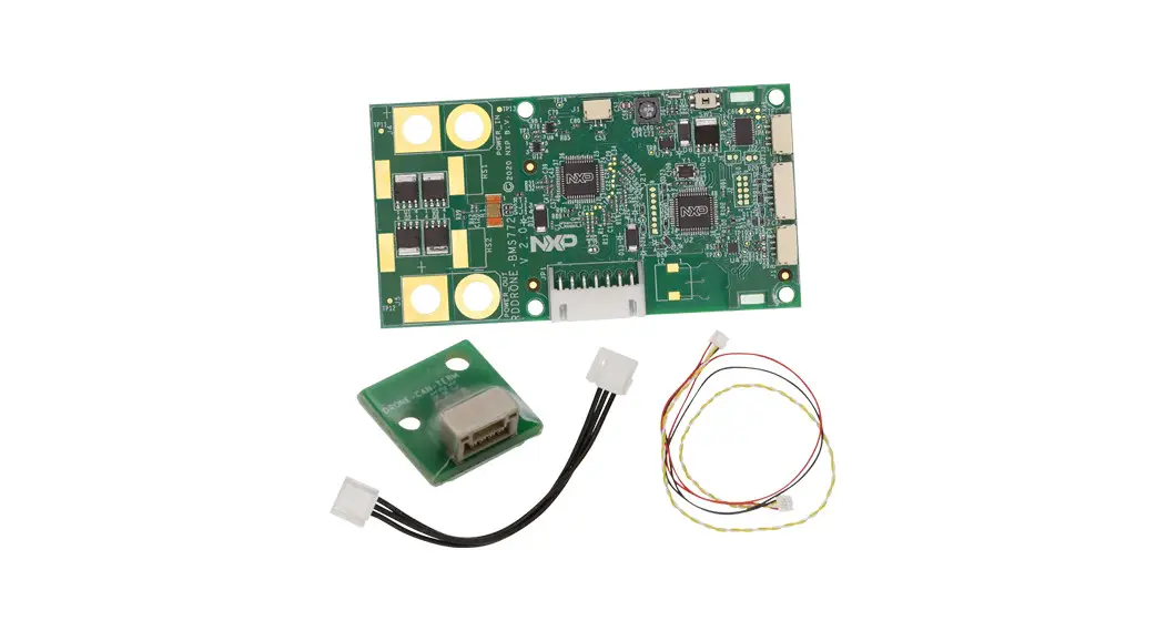
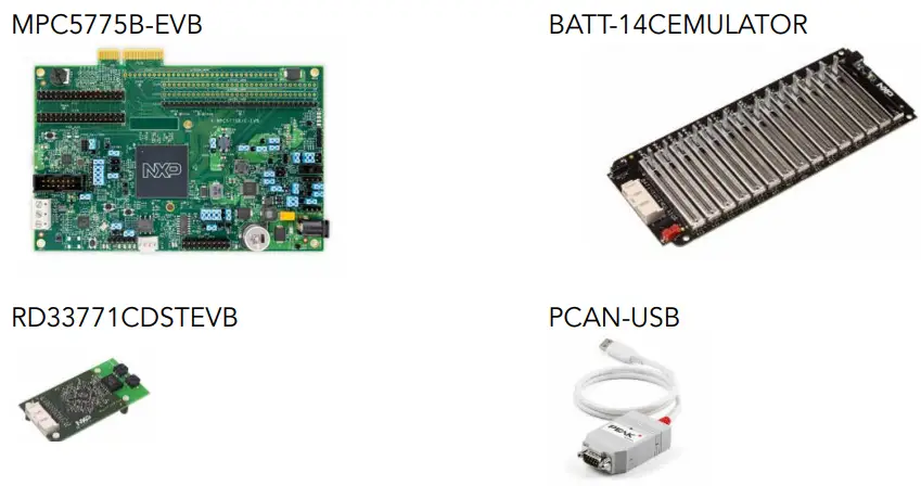
REQUIRED HARDWARE FOR THE DEMO
| Board Part Number | Description | Weblink |
| MPC5775B-EVB | MPC5775B EVB with MC33664 TPL interface support | NXP link |
| RD33771CDSTEVB | MC33771C based Battery Cell Controller Evaluation board | NXP link |
| BATT-14CEMULATOR | 14 Cell battery emulator board | NXP link |
| PCAN-USB adapter | CAN monitor | PHYTools |
REQUIRED SOFTWARE FOR THE DEMO
| Item | Description | Weblink |
| S32 Design Studio IDE | NXP S32 Design Studio IDE for PowerPC V2.1 | NXP link |
| MPC5775B-BatterySystem SDK | S32DS based Jumpstart demo software for the MPC5775B-EVB using SDK 3.0.0 with FreeRTOS | NXP link |
| MPC5775B-BatterySystem GUI | Graphic User Interface software to monitor battery status via CAN interface. | NXP link |
| Python 3.7 64-bit with PyQt5 and NumPy | Install the Python 64-bit version, then install the PyQt5 and NumPy packages | Python link |
 Download Software
 Download Software
Download installation software and documentation under “Jump Start Your Design” at nxp.com/MPC5775B-BatterySystem
GET TO KNOW THE BMS DEMO
Note: Numbers correspond to the steps to follow for setup.
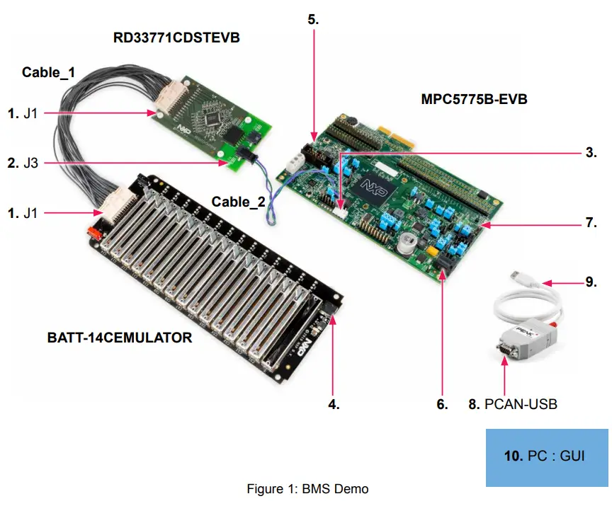
STEP-BY-STEP INSTRUCTIONS FOR BMS DEMO SETUP
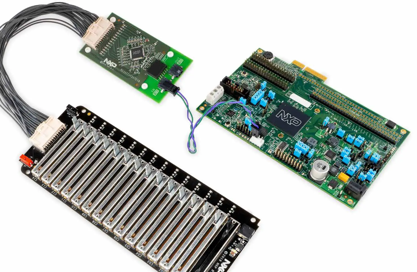
1. Connect BATT14CEMULATOR and RD33771CDSTEVB
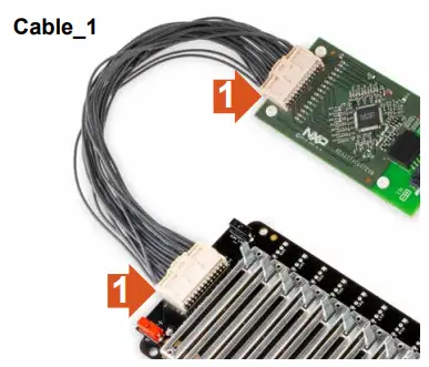
Connect the battery cell emulator board (BATT-14CEMULATOR) and the cell controller board (RDCV33771C) using Cable_1.
2.Connect RD33771CDSTEVB and MPC5775B-EVB for TPL link
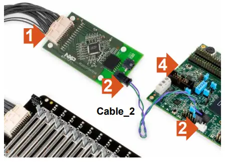 Connect the cell controller board with the battery management board using the Cable_2 as shown in the figure to the right. This will establish the TPL link for communication.
Either J1 or J2 can be connected to the RD33771CDSTEVB.
User must connect positive (+) terminal of MPC5775B-EVB’s BMS interface connector (J118 – pin 3,4 ) to BMS cell controller module positive (+) terminal and negative terminal to the negative terminal as shown in the next slide.
BMS APPLICATION SPECIFIC CONNECTIONS
| APPLICATION-SPECIFIC ITEM | MPC5775B-EVB | MPC5775E-EVB |
| Battery management connector | J118 | Not supported |
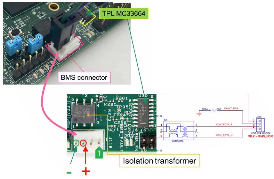
| PIN | DESCRIPTION | J118 REMARKS |
| 1 | FAULT_IN | For TPL connection use pin 3 and 4. Connect the positive to positive and negative to negative. |
| 2 | FAULT_RTN | |
| 3 | TPL_P positive terminal | |
| 4 | TPL_N negative terminal |
3. Power up BATT14CEMULATOR&RD33771CDSTEVB
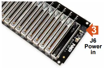 Connect the power supply to the BATT14CEMULATOR. Powering the emulator board also powers the RDCV33771C cell controller board.
4. Connect the USB serial cable to MPC5775B-EVB and PC
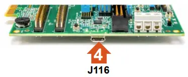 Connect the micro-USB cable to the J116 micro-USB port for OpenSDA connection for programming and debug.
Connect the USB side to the computer. Refer to MPC5775B-EVB QSG for more information.
5. Power the MPC5775B-EVB
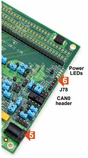 Connect 12V power supply to the power socket on the Development board.
Make sure the status LEDs D14, D15, D16, and D32 for voltage levels 3.3V, 5V, 1.25V, and 12V supply respectively are glowing green on the board.
6. Connect the CAN with the PCAN tool
Connect CAN High and Low signals of J78 to PCAN tool CAN high and low.
MPC5775B-EVB:
J78 pin 2 is CAN0_High
J78 pin 3 is CAN0_Low
| PIN | DESCRIPTION | REMARKS |
| 1 | 5V | TJA1145T PHY needs to be enabled via DSPI_B, Chip select CSB1. Use J58 & J60 for CAN module selection. By default connected to FlexCAN_A/MCAN0. |
| 2 | CAN1_0H | |
| 3 | CAN1_0L | |
| 4 | GND |
7. Connect the CAN with the PCAN tool
Connect the CAN_H and CAN_L signals of J78 of MPC5775B-EVB to PCAN USB CAN_H (pin 7) and CAN-L (pin 2) via two jumper cables.
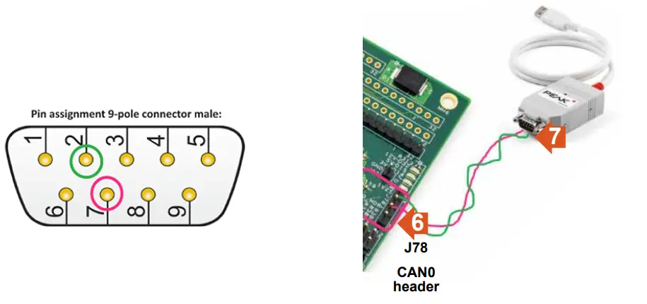
Pin Configuration
| 1. +12V/+5V/Not Connected 2. CAN-L 3. CAN-GND/Not Connected 4. Not Connected 5. Not Connected | 6. CAN-GND/Not Connected 7. CAN-H 8. Not Connected 9. +12V/+5V/Not Connected |
8. Import the MPC5775B_BMS_SDK_SW project to S32DS
Run the S32DS for PowerPC 2.1 and follow the steps “a to f” to import the MPC5775B_BMS_ SDK_SW project.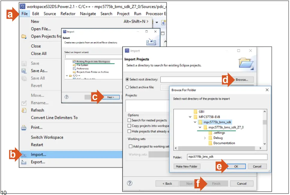 9. Generate Processor Expert Codes and Compile the binary image
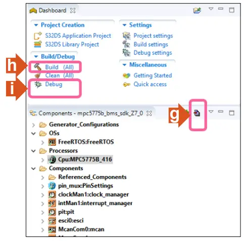 Then build and run the program.
Follow the steps “g” to “i” to generate the processor expert codes, compile and build the image. Refer to the MPC5775B-EEVB QSG to debug/flash the image.
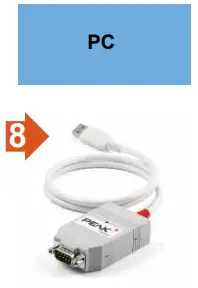
10. Connect the PCAN tool USB to the PC
Connect the USB connector of the PCAN tool to the computer USB port.
11. Run the GUI software
Open the windows “Command Prompt” and execute the “Py Main.py” in the command shell.
“Main.py” python file included in the GUI folder.
Make sure you first install the Python 3.7 64-bit version and necessary packages PyQt5 and NumPy prior to the above step. Refer the readme file in the downloaded software GUI folder.

12. Setup the GUI link
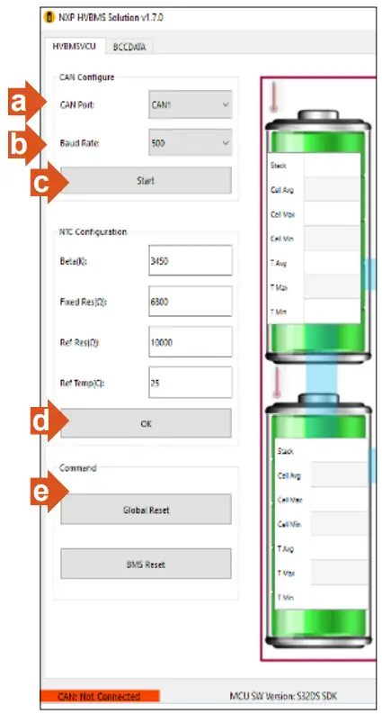
a. Select CAN1
b. Set CAN baud rate to 500Kbps
c. Click “Start”, now the CAN link establish with the main controller board
d. Click “OK”
e. Initiate global reset to BMS system by clicking “Global Reset”
f. User able to observe the battery pack information shown in next slide
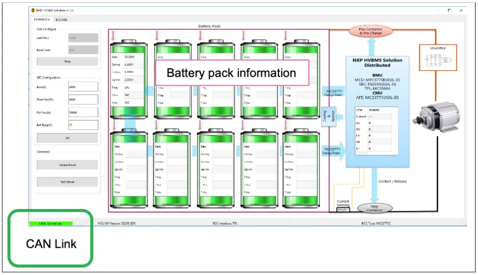
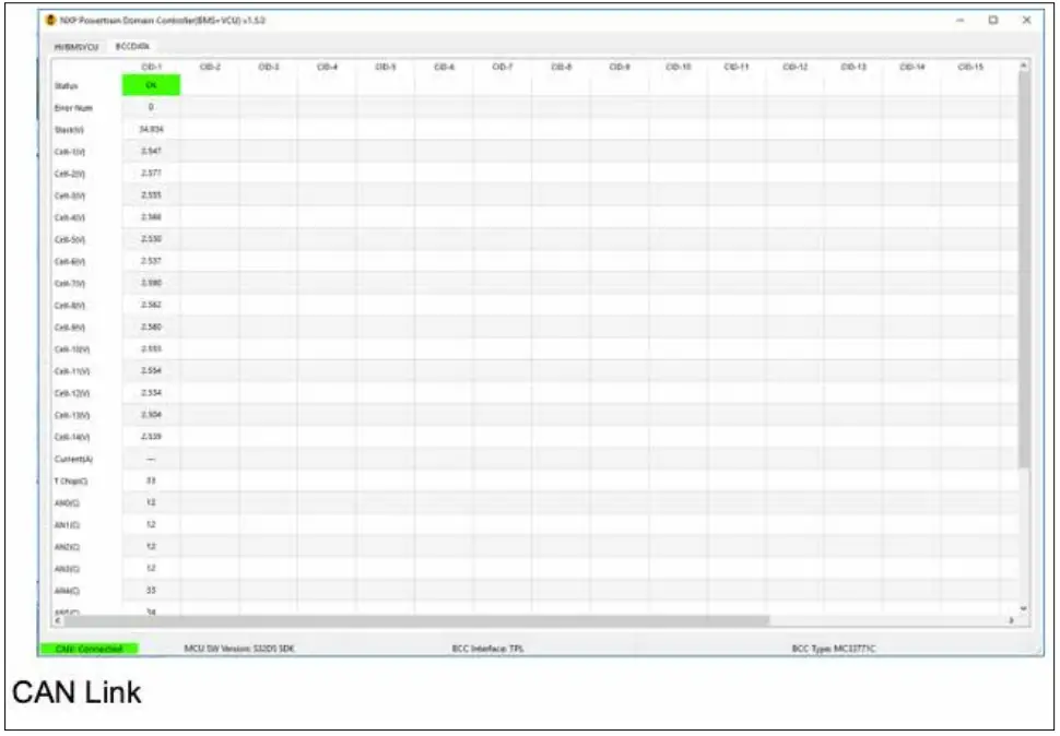
GUI INTERFACE 1/2
The figure below shows the GUI interface after communication has been established.
GUI INTERFACE 2/2
Adjust the battery levels via BATT-14CEMULATOR and observe the GUI for individual cell data in the “BCCDATA” tab.
REFERENCES
| DOCUMENT | DESCRIPTION | LOCATION |
| MPC5775B-E-EVB-QSG | Quick Start Guide of MPC5775B-EVB | NXP web site |
| AN12875 | Getting Started with MPC5775E-EVB and MPC5775B-EVB | NXP web site |
| MPC5775E RM | MPC5775E RM/MPC5775B Reference Manual | NXP web site |
| MPC5775E DS | MPC577E/MPC5775B Data Sheet | NXP web site |
| OpenSDA | OpenSDA User’s guide | NXP web site |
| S32DS | S32 Design Studio for Power Architecture v2.1 – Windows/Linux | NXP web site |
| MC33FS6520LAE | MC33FS6520 System Basis Chip (Power supply and drivers) Data Sheet | NXP web site |
| FS65SBC-SDK-SW | FS6500/FS4500 Generic Embedded Software Driver (Software Development Kit) | NXP web site |
| TJA1100 | TJA1100 100BASE-T1 PHY For Automotive Ethernet | NXP web site |
| TJA1145 | High-speed CAN transceiver for partial networking | NXP web site |
| MC33664_SDS | Isolated Network High-Speed Transceiver Short Data Sheet | NXP web site |
| MC33664 | Isolated Network High-Speed Transceiver Full Data Sheet | NXP web site |
| MC33771C | Battery Cell Controller Full Data Sheet | NXP web site |
| RD33771CDSTEVB | Evaluation Board for MC33771C BCC with Isolated Daisy Chain Communication | NXP web site |
| BATT-14CEMULATOR | 14-Cell Battery Pack Emulator to Supply MC33771C BCC EVs | NXP web site |
| HM2102NL | Pulse Electronics Dual BMS transformer | Pulse Electronics |
| HM2103NL | Pulse Electronics Single BMS transformer | Pulse Electronics |
SUPPORT
Visit www.nxp.com/support for a list of phone numbers within your region.
WARRANTY
Visit www.nxp.com/warranty for complete warranty information.
AUTOMOTIVE COMMUNITY
Visit https://community.nxp.com/community/s32
PRODUCT COMMUNITY
Visit https://community.nxp.com/community/s32/MPC5xxx
Get Started
Download installation software and documentation under “Jump Start Your Design” at nxp.com/MPC5775B-BatterySystem
nxp.com/MPC5775B-BatterySystem
NXP and the NXP logo are trademarks of NXP B.V. All other product or service names are the property of their respective owners. The Bluetooth® word mark and logos are registered trademarks owned by Bluetooth SIG, Inc.
and any use of such marks by NXP Semiconductors is under license.© 2020 NXP B.V.
Document Number: BMSSOLQSG REV 0
www.nxp.com


