![]()
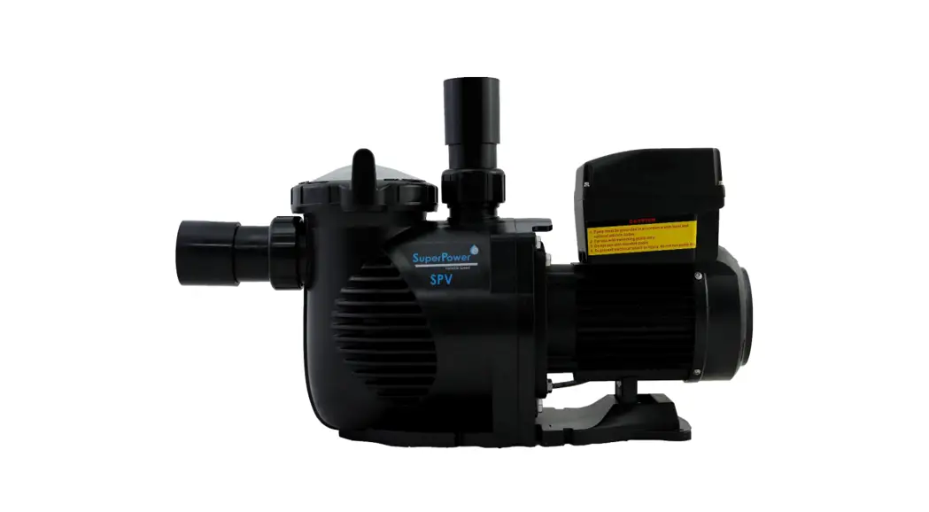
![]() SPV150 Super-Power Swimming Pool Variable Speed Pump
SPV150 Super-Power Swimming Pool Variable Speed Pump
User Guide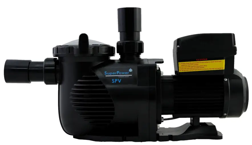
SPV150
SUPER-POWER
Swimming pool Variable Speed Pump
USER GUIDE
IMPORTANT SAFETY INSTRUCTIONS
The user guide you are holding includes essential information on the safety measures to be implemented for installation and start-up. Therefore, the installer, as well as the user, must read the instructions before beginning installation and start-up. Keep this manual for future reference.
The pump should be installed according to your local electrical installation ordinances and regulations. Only qualified, licensed personnel should install the pump and the wiring.
This appliance cannot be used by persons (including children) with reduced physical, sensory or mental capabilities or lack of experience and knowledge unless they have been given supervision or instruction concerning the use of the appliance in a safe way and understand the hazards involved. Children must not play with the appliance.![]() CAUTION
CAUTION![]() Hazardous suction. Can trap hair or body parts, causing severe injury or death. Do not block suction.
Hazardous suction. Can trap hair or body parts, causing severe injury or death. Do not block suction.
Correct Disposal of this product![]() This marking indicates that this product should not be disposed of with other household wastes throughout the EU. To prevent possible harm to the environment or human health from uncontrolled waste disposal, recycle it responsibly to promote the sustainable reuse of material resources. To return your used device, please use the return and collection systems or contact the retailer where the product was purchased. They can take this product for environmentally safe recycling.
This marking indicates that this product should not be disposed of with other household wastes throughout the EU. To prevent possible harm to the environment or human health from uncontrolled waste disposal, recycle it responsibly to promote the sustainable reuse of material resources. To return your used device, please use the return and collection systems or contact the retailer where the product was purchased. They can take this product for environmentally safe recycling.
INSTALLATION
- Install the pump as close to the pool as possible, preferably in a dry, well-ventilated area away from direct sunlight. Protect the pump from excessive moisture.
- Place the pump as close to the water source as possible, so that the suction pipe is short, straight, and direct to reduce friction loss. Don’t install the pump at more than 3 meters of geometrical height from the water level.
- Before installing the pump, make sure that the surface is solid, elevated, rigid, and vibration free.
- Secure the pump to the base with screws or bolts to limit the vibration and the stress on the pipe or the joints.
- Leave enough space for gate valves in suction and discharge piping, if required.
- Connect the suction and discharge pipe to the outlet and inlet of the swimming pool.
- Make sure that floor drainage is adequate to prevent flooding.
- This pump must be equipped with an isolating transformer or through a residual current device (RCD) having a rated residual operating current not exceeding 30 mA.
- Make sure that the pump and piping are accessible for servicing.
Note: The pump suction and discharge connections are molded in thread stops, DO NOT try to screw the pipe beyond these stops.
2.1 START-UP
The wide range of pump settings makes it suitable for multiple purposes. The pump controller is used to program motor speeds and schedules as described in Chapter “Operation” of this manual.
WARNING:
- NEVER run the pump dry! Running the pump dry will damage seals, causing leakage and flooding. Fill the pump with water before starting.
- Always STOP THE PUMP before and RELEASE ALL PRESSURE from the pump and the piping system before proceeding.
- NEVER tighten or loosen screws while the pump is operating.
- Do not block the pump suction.
2.2 PRIMING PUMP
- Release all air from the filter and piping system (consult your filter user manual).
- In a flooded suction system (water source higher than the pump), the pump will prime itself when suction and discharge valves are opened.
- If the pump is not installed in a flooded suction system, unscrew and remove the pump lid and fill it with water.
WARNING: Tighten/untighten the pump lid by hand only.
PROGRAMMABLE CONTROLLER
3.1 OVERVIEW
This controller matches with the variable speed drive for the swimming pool variable speed pump. Functions are shown below:
- Timer: Built-in time clock.
- Control Parameters: Power usage and motor running speed (RPM) display.
- Pre-set Running Speed: 3 pre-set running speeds.
- Parameter settings: Real-time clock, 3 pre-set running speeds, 3 schedule settings, self- priming settings.
- Error display: Overcurrent, Overvoltage, Under-voltage, Overheating fault code.
- Auto-recovery: After an overcurrent, Overvoltage, Under-voltage, Overheating or Power failure, the settings will be restored as before the error.
- Power failure recovery: When the power is reconnected, the settings will be restored as before the error appeared.
3.2 CONTROLLER DISPLAY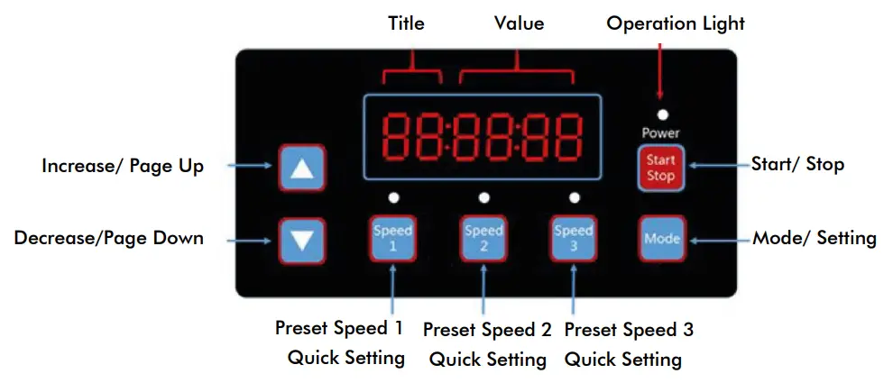
| S1 | S2 | S3 | Running Light | Operation Light Flashing | |
| Pre-set Speed 1 Enable | 1 | 0 | 0 | X | 0 |
| Pre-set Speed 2 Enable | 0 | 1 | 0 | X | 0 |
| Pre-set Speed 3 Enable | 0 | 0 | 1 | X | 0 |
| In Operation | X | X | X | 1 | 0 |
| Warning | 1 | 1 | 1 | 1 | 1 |
3.3 PROGRAM FLOW CHART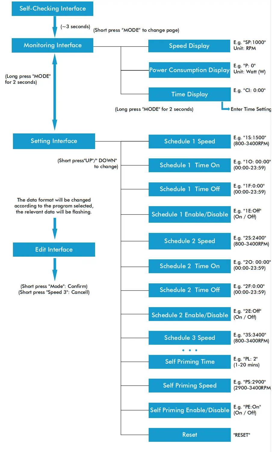
3.4 BUTTONS CONTROL
| Action | Monitoring Interface | Setting Interface | Edit Interface | Error/Auto Recovery |
| Short press “UP” | Current speed +10 RPM | Page Up | Add current value | N/A |
| Long press “UP” | Current speed increase rapidly | Page Up rapidly | Add current value rapidly | N/A |
| Short press “DOWN” | Current speed -10 RPM | Page Down | Reduce current value | N/A |
| Long press “DOWN” | Current speed decrease rapidly | Page Down rapidly | Reduce current value rapidly | N/A |
| Short press “MODE” | Change page | Enter Edit Interface | Confirm change, back | N/A |
| Long press “MODE” | When in the Time Display page: Enter Time Setting When on other pages: Enter Setting Interface | Enter Monitoring Interface | N/A | N/A |
| Short press “Start/Stop” | Start / Stop | Start / Stop | N/A | Auto Recovery |
| Long press “Start/Stop” | N/A | N/A | N/A | N/A |
| Short press “Speed 1” | Set current speed to preset speed 1 | Switch to preset speed 1 | Edit cursor move left | N/A |
| Long press “Speed 1” | N/A | N/A | Edit cursor move left rapidly | N/A |
| Short press “Speed 2” | Set current speed to preset speed 2 | Switch to preset speed 2 | Edit cursor move right | N/A |
| Long press “Speed 2” | N/A | N/A | Edit cursor moves right rapidly | N/A |
| Short press “Speed 3” | Set current speed to preset speed 3 | Switch to preset speed 3 | Cancel change, back | N/A |
| Long press “Speed 3” | N/A | N/A | N/A | N/A |
3.5 PROGRAMMING INSTRUCTIONS
3.5.1. SCHEDULE
- There are 3 schedule settings available, the pre-set speed at 1500 RPM, 2400 RPM and 3400 RPM.
- Each schedule setting has 4 parameters: “Running Speed”, “Time on”, “Time off”, and “Enable/ Disable”.
- Programmed Schedule Priority: Schedule 1 > Schedule 2 > Schedule 3.
- If more than 1 schedule is enabled within the same time period, the controller will operate only with the highest priority schedule and speed. The corresponding indicator light will turn on.
- If all schedules are completed according to their pre-set times, the controller will return to the condition before setting the schedule.
- When one of the programmed schedules is running, you can press the following buttons in the monitoring interface:
A . If you press “Start/Stop”, the pump will stop; the last running speed will be recorded and the operation light will remain turned on.
b. If you press “Up” or “Down”, the running speed will increase/reduce by 10 RPM from the current speed, and the operation light will turn off.
c. If you press “Speed 1/2/3”, the current speed will be replaced with the new selected speed, and the corresponding speed indication light will turn on. - The scheduled settings and auto-recovery cannot contradict each other. When there is an error, the variable speed driver will restore the settings to those before the error. (The priority setting is still applicable).
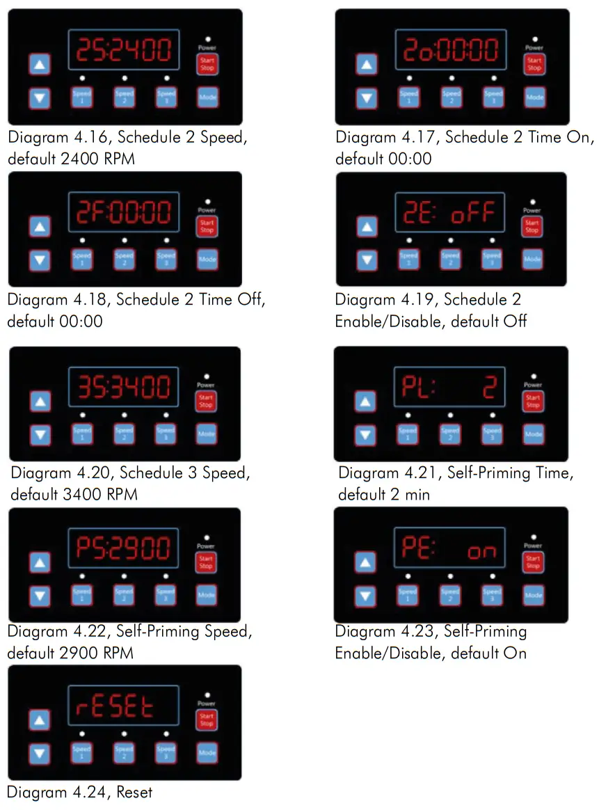
3.5.2. SELF-PRIMING
- The Self-priming setting has 3 parameters “Self-priming Time”, “Self-priming Speed”, “Enable/Disable”.
- The Self-priming function will be activated if the function is enabled, the running speed is lower than the “Self-priming Speed” and the running time is less than the “Self-priming Time”.
- Self-priming default as “Enable”.
3.5.3. AUTO-RECOVERY
- Auto-recovery is a core function, there are no setting options available.
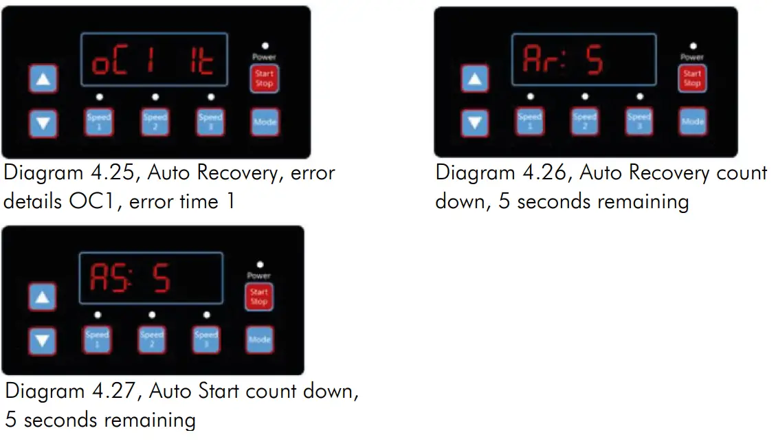
- In case of over-current, Overvoltage, or Under-voltage error, the variable speed driver will recover automatically and it will restart after 10 seconds.
- During the first 5 seconds, the display will show “error details/error times” (e.g. “OC1
1T”). During the following 5 seconds, the display will show the “Count down details / Count down time” (e.g. “AR 5” or “AS 5”). - If two errors happened in an interval of fewer than 60 seconds, the auto-recovery time will increase once. If it increases up to 3 times, the system will direct you to the Error menu and will not auto-recover itself.
- Press the “Start/Stop” button to cancel the count down during the auto-recovery process and to activate the auto-recovery immediately.
3.5.4. POWER FAILURE RECOVERY
- The current settings (Enable/Disable, current speed, scheduled settings) are protected by the capacity; the memory will be kept for 72 hours.
- When the power is reconnected, the variable speed driver will restore the settings as before the error appeared.
3.5.5 REAL-TIME CLOCK
- The real-time clock display time appears in “hours: minutes”
- Keep the “MODE” button pressed at the “Time Display Page” to enter into “Time Setting”.
3.5.6 RESET
At the setting interface, go to the Reset menu – display “RESET”, press “Mode” shortly, the content will be flashing, and then press “Mode” again to reset completely. Press “Speed 3” while the content is flashing to stop the reset.
OPERATION
4.1 START-UP
After starting up the pump, the driver will run the self-checking procedure by scanning the display and turning on the operation light (Diagram 4.1).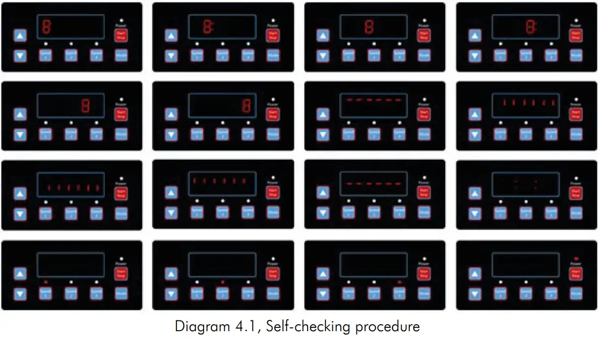 When there is a communication error between the controller and the variable speed driver, the communication error will be displayed, as shown in Diagram 4.2.
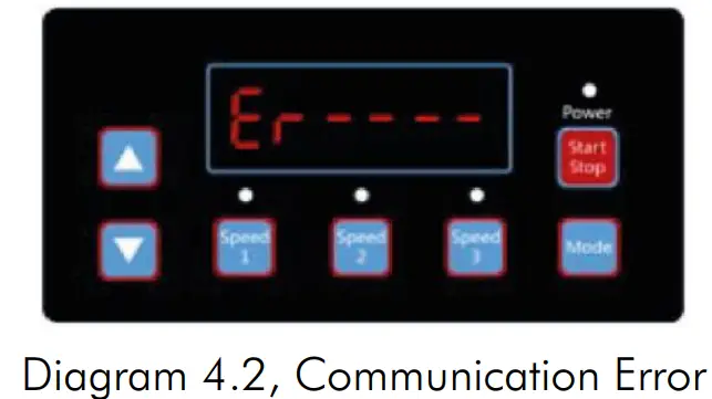
4.2 MONITORING INTERFACE
After starting up the pump, enter into the “Monitoring Interface”, as shown in Diagram 4.3. Press “Mode” to interchange between the speed or time display page (Diagram 4.3 4.5).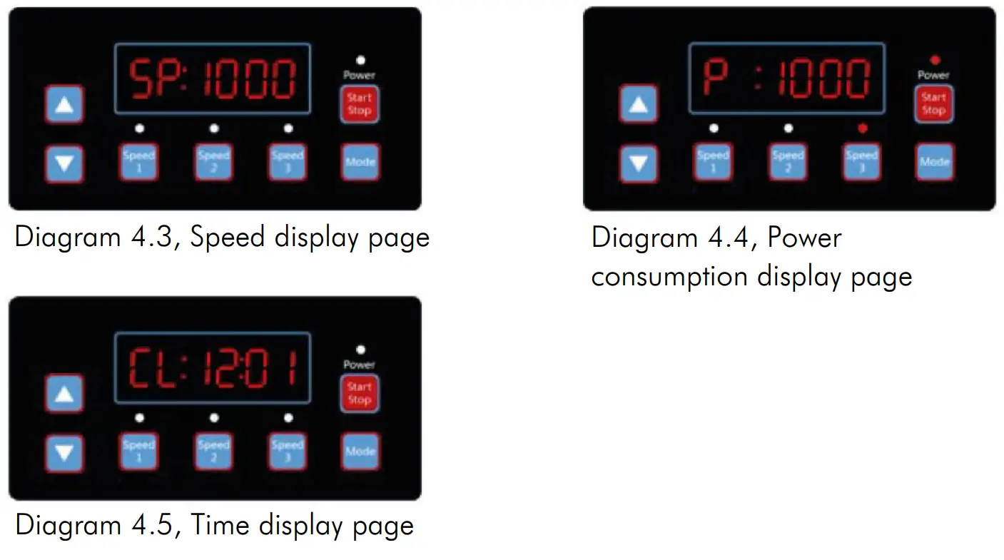 Press “Speed 1” to “Speed 3” to change the pre-set speed; the corresponding light will turn on (Diagram 4.6 4.8).
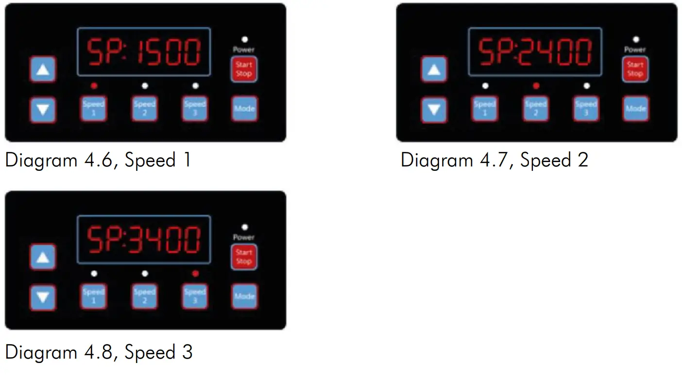
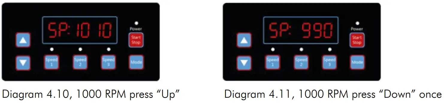
Press “Run” at any time to start/stop the variable speed driver; the operation light will turn on/off (Diagram 4.9).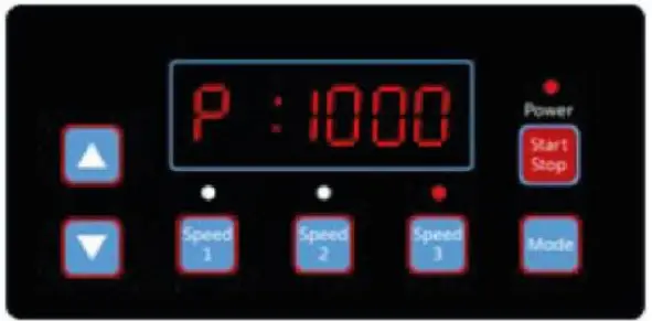
Diagram 4.9, Power consumption display, Speed 3 Press “Up” or “Down”, to increase or reduce the RPM by 10, as shown in Diagrams 4.10-4.11.
Keep “Mode” pressed in order to enter into the setting interface:
4.3 SETTINGS INTERFACE
Press “Mode” shortly to move to “Schedule 1 Speed”, “Schedule 1 Time On”, “Schedule 1 Time Off”, “Schedule 1 Enable/Disable”, “Schedule 2 Speed”, “Schedule 2 Time On”, “Schedule 2 Time Off”, “Schedule 2 Enable/Disable”, “Schedule 3 Speed”, “Self-priming Time”, “Self-priming Speed”, “Self-priming Enable/Disable”, “Auto-recovery” pages (Diagram 4.12- 4.23).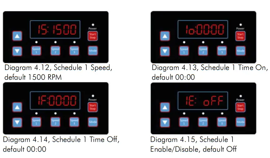
4.4 EDIT INTERFACE
Keep the “Mode” button pressed at the time display page in the monitoring interface or press “Mode” shortly at any display page to enter the edit interface. At the edit interface, the modifiable area will start flashing. Press “Up” or “Down” to change the value, press “Speed 1” or “Speed 2” to move left or right. Press “Mode” shortly to confirm the editing or press “Speed 3” shortly to cancel.
4.5 AUTO-RECOVERY
When there is an Overcurrent, Overvoltage, Under-voltage or Overheating error, the system will recover itself automatically. If two errors happen in less than a 60 seconds interval, the auto-recovery time will increase once. If the auto-recovery increases by 3 times, the system will direct you to the Error menu, and will not execute the auto-recovery. The Auto-recovery page will display the error details (Diagram 4.25) during the first 5 seconds and the countdown details during the following 5 seconds (Diagram 4.26).
Press the “Start/Stop” button to cancel the countdown during the auto-recovery process or to activate the auto-recovery immediately. (without activating the auto-run. If there is an error and the variable speed driver is in operation, then after the auto-recovery the system will display the auto-start page. The auto-start page will show the error details (same as auto-recovery, which will last for 5 seconds) and the countdown details) as shown in Diagram 4.27. Press “Run” to cancel the procedures and to auto-recover immediately (the default settings of the variable speed driver will appear).
4.6 ERROR MENU
The Error Menu display as shown in Diagram 4.28, will show all error details and all lights will start flashing. Press “Run” shortly at the error menu, to auto-recover the variable speed driver (keep the driver Off).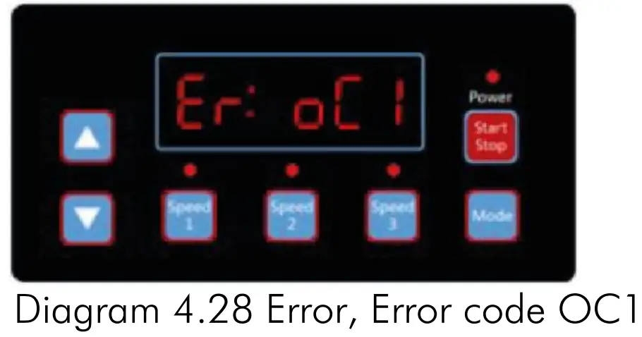
ERRORS DESCRIPTION
5.1 COMMUNICATION ERROR
If the communication error (“ER —“) appears, make sure that the plug has good contact with the current and reset the system by unplugging the equipment from the power supply, wait at least 60 seconds before reconnecting. If the error continues, contact your Emaux technical service.
5.2 OPERATION ERRORS
When the controller is not working, an error code will be shown on the controller display. E.g. “Er: OV”. Press the “Start/Stop” button to restore the controller. The common error codes are the following:
| Error | Description | Reason |
| OC | Overcurrent: driver current output exceeds the threshold (200% of rated current). | – Driver output failure – The driver IPM module is damaged |
| OVEN | Overvoltage: the main circuit DC voltage exceeds the threshold. | – Exceeded power from the power supply – Power supply voltage exceeds the control settings |
| UV | Under-voltage: the main electric current is too low. | – Ambient temperature is too high – Supply voltage fluctuation is too large |
| OH | Overheating: the motor heat sink is overheated. | – Ambient temperature is too high – Motor Cooling Fan does not work |
ROUTINE MAINTENANCE
The only routine maintenance needed is the inspection/cleaning of the trap basket. Debris or trash collected in the basket will choke off the water flow through the pump. Follow the instructions below in order to clean the trap:
- Stop the pump, close the gate valve in suction and discharge, and release all pressure from the system before proceeding.
- Unscrew the trap lid (turn counterclockwise).
- Remove the strainer basket and clean. Make sure all the holes in the basket are clear, flush
the basket with water and replace it in the trap with a large opening at the pipe connection port (between ribs provided). If the basket is replaced backward, the cover will not fit on the trap body. - Clean and inspect the lid ring; reinstall the trap cover.
- Clean the ring groove on the trap body and replace the lid. To help keep the lid from sticking, tighten it by hand only.
- Prime the pump (see priming instructions above).
AFTER-SALES SERVICE
Refer all service needs to your local agent or dealer as his knowledge of your equipment makes him the best-qualified source of information. Order all the repair parts through your dealer. Give the following information when ordering repair parts.
- Unit name on the plate data or serial number on the label.
- Description of the part.
REPLACEMENT PARTS
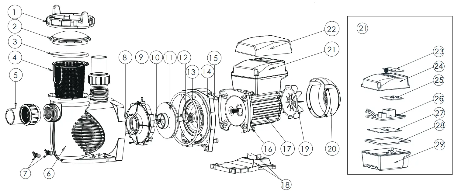
| Key No. | Part No. | Description | Qty |
| 1 | 01021143 | Nut for Lid | 1 |
| 2 | 01041057 | Transparent Lid | 1 |
| 3 | 02010253 | O-Ring for Lid | 1 |
| 4 | 01112080 | Basket | 1 |
| 5 | 89023801 | 1.5’’ Union | 2 |
| 6 | 01021144 | Pump Body | 1 |
| 7 | 89021307 | Drain Plug with O-Ring | 2 |
| 8 | 02010245 | O-Ring with diffuser | 1 |
| 9 | 01112081 | Diffuser | 1 |
| 10 | 89020719 | Screw for Impeller with O-Ring | 1 |
| 11 | 01311058 | Impeller for EPV150 & SPV150 | 1 |
| 12 | 04015065 | ¾’’ Mechanical Seal | 1 |
| 13 | 02010246 | O-Ring for Flange | 1 |
| 14 | 01021145 | Flange | 1 |
| 15 | 89020720 | M8 x 35 Screw with Washer for Motor | 4 |
| 16 | 03011075 | M8 x 30 Screw | 4 |
| 17 | 04020140 | SPV150 Motor | 1 |
| 18 | 01112082 | Base | 1 |
| 18 | 02010211 | Arch Cushion for Base | 1 |
| 19 | 01031027 | Fan | 1 |
| 20 | 01321032 | Fan Cover | 1 |
| 21 | 89023901 | Controller for SPV150 | 1 |
| 22 | 01041061 | Lid for Controller | 1 |
| 23 | 04015057 | Switch Keys | 1 |
| 24 | 03039920 | Cover for Programmable Controller | 1 |
| 25 | 04015060 | SPV Operation panel (PCB) | 1 |
| 26 | 04015061 | PFC PCB | 1 |
| 27 | 04015062 | Driver | 1 |
| 28 | 02021092 | Cushion for Cover | 1 |
| 29 | 03039919 | Shell for Programmable Controller | 1 |
DIMENSIONS
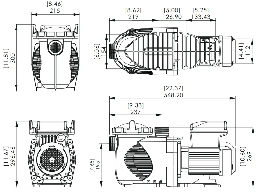
SPECIFICATIONS
| Code | Model | Voltage/ Frequency | Connection | Maximum input power | Horse power | RPM |
| 88029807 | SPV150 | 220-240V 50-60 Hz | 1.5’’/ 50mm | 1,50 (kW) | 1,5 HP | 800-3400 RPM |
TROUBLESHOOTING
Problem description | Possible causes |
| The motor does not start | 1. Disconnect switch or circuit breaker in the off position 2. Fuses blew or thermal overload open 3. Locked motor shaft 4. Motor windings burned out 5. Defective starting switch inside single phase motor 6. Disconnected or defective wiring 7. Low voltage |
| The pump does not reach full speed | 1. Low voltage 2. Pump connected to the wrong voltage |
| Motor overheats (protector trips) | 1. Low voltage 2. Motor windings connected to the wrong voltage on dual voltage model |
| Pump delivers no water | 1. Pump is not primed 2. Closed valve in suction or discharge line 3. Leakage or air into the suction system 4. Impeller clogged |
| Leakage of water at the shaft | 1. Shaft seal requires replacement |
| Low pump capacity | 1. Valve in the suction or discharge line partly closed 2. Suction or discharge line partly plugged 3. Suction or discharge line too small 4. Plugged basket in skimmer or hair and lint strainer 5. Dirty filter 6. Impeller clogged |
| High pump pressure | 1. Discharge vale or inlet fittings closed too much 2. Return lines too small 3. Dirty filters |
| Noisy pump and motor | 1. Plugged basket in skinner or hair in lint strainer 2. Worn motor bearings 3. Valve in suction line partly closed 4. Suction line partly plugged 5. Vacuum hose plugged or too small 6. Pump not supported properly |
| Air bubbles at inlet fittings | 1. Leakage of air into the suction line in connections or valve stem 2. Cover gasket of hair and lint strainer needs cleaning 3. Low water level in the pool |
Note: If the above recommendations of this manual do not solve your particular problem(s), please contact your local service agent for further assistance.
WARRANTY POLICY
| WARRANTY FOR SPECIFIC PRODUCTS | |
| Product | Warranty Period |
| Pumps | 1 year |
12.1 EXCEPTIONS THAT MAY RESULT IN DENIAL OF A WARRANTY CLAIM
- Damage caused by careless handling, improper repackaging or shipping.
- Damage due to misapplication, misuse, abuse or failure to operate and install the
equipment as specified in this manual. - Damage caused by misuse, abuse, or failure to operate and install the equipment out of the scope of a professional level demanded in similar equipment or installation type.
- Damage due to unauthorized product modifications or failure to use Emaux original replacement parts.
- Damage caused by negligence or failure to properly maintain products as specified in this manual.
- Damage caused by failure to maintain water chemistry in conformity with the standards of the swimming pool industry for any length of time.
- Damage caused by water freezing inside the product.
- Accident damage, fire, natural disaster or other circumstances outside the control of Emaux.
- Items repaired or altered in any way by any person that is not authorized by Emaux.
- Wear & tear parts.
12.2 CLAIM PROCESS
Summary of Claim Process in 3 steps:
- Claim: Customer provides complete details of the claim which include:
a. Information about the failed product such as the part number(s) and serial number(s).
b. Description of the complaint/failure.
c. Pictures


