![]()
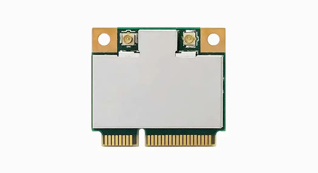
![]() WNFQ-268AXI(BT) / WNFQ-268AX(BT)
WNFQ-268AXI(BT) / WNFQ-268AX(BT)
WiFi 6 or 6E M.2 Tri Band WiFi Module
User Manual
Specification
| Standards | IEEE 802.11aVac/a/b/g/n (2T2R) Bluetooth V5.2, V5.1, V5.0, V4.2, V4.1, V4.0LE, V3.0, V2.1+EDR |
| Chipset | Qualcomm Atheros WCN6856 |
| Data Rate | 802.1lb: 11Mbps 802.11a/g: 54Mbps 802.11n: MCSO-15 802.11ac: MCS0-9 802.11ax: HE0-11 Bluetooth: 1 Mbps, 2Mbps and Up to 3Mbps |
| Operating Frequency | IEEE 802.11a4ac/a/b/g/n ISM Band, 2.412GHz-2.484GHz, 5.150GHz-5.850GHz ,5.925-7.12561-1z(FCC only) *Subject to local regulations |
| Interface | WLAN: PCIe Bluetooth: USB |
| Form Factor | M.2 2230E Key and AE key |
| Antenna | 2 x IPEX MHF4 connectors Ant 1 for WLAN/BT, Ant 2 for WLAN |
| Modulation | Wi-Fi: 802.1lb: DSSS (DBPSK, DUSK, CCK) 802.11g: OFDM (BPSK, QPSK, 16-QAM, 64-QAM) 802.11n: OFDM (BPSK, QPSK, 16-QAM, 64-QAM) 802.11a: OFDM (BPSK, QPSK, 16-QAM, 64-QAM) 802.11ac: OFDM (BPSK, QPSK, 16-QAM, 64-QAM, 256-QAM) 802.11ax: OFOMA (BPSK, QPSK, 16-QAM, 64-QAM, 256-QAM, 1024-0AM) BT: Header: GFSK Payload 2M: n/4-DQPSK Payload 3M: 8-DPSK |
| Operating Voltage | DC 3.3V |
| Operating Temperature Range | WNFQ-268M1(13T) Operating Temp: -40°C “75°C; WNFQ-268AX(BT) Operating Temp: -10°C -65°C |
| Storage Temperature Range | -45°C-90°C |
| Humidity (Non-Condensing) | 5%-90% (Operating) 59G-90% (Storing) |
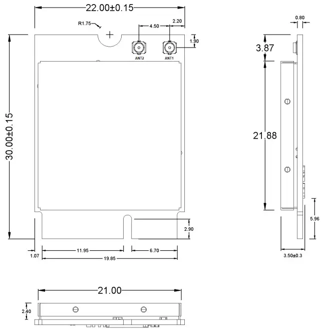
| Dimension Lx W x H (in mm) | 30mm(± 0.15mm) x 22mm(± 0.15mm) x 3.Smm(± 0.3mm) |
| Weight (g) | 3.2g |
| Security | 64/128-bits WEP, WPA, WPA2, WPA3, 802.1x |
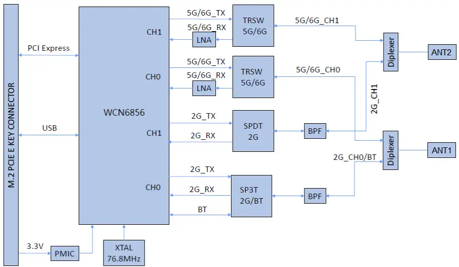
Block Diagram
Mechanical Dimension (mm)
Pin Assignment (TBD)
The following section illustrate signal pin-outs for the module connector.
| TOP | |||
| Pin# | Pin Name | Type | Description |
| 1 | GND | G | Ground connections |
| 3 | USB D+ | I/O | USB serial differential data Positive |
| 5 | USB D- | I/O | USB serial differential data Negative |
| 7 | GND | G | Ground connections |
| 9 | SDIO CLK/SYSCLK | NC | No Connection |
| 11 | SDIO CMD | NC | No Connection |
| 13 | SDIO DATAO | NC | No Connection |
| 15 | SDIO DATA1 | NC | No Connection |
| 17 | SDIO DATA2 | NC | No Connection |
| 19 | SDIO DATA3 | NC | No Connection |
| 21 | SDIO WAKE# | NC | No Connection |
| 23 | SDIO RESET#/TX BLANKING | NC | No Connection |
| 25 | NOTCH FOR KEY E | NC | No Connection |
| 27 | NOTCH FOR KEY E | NC | No Connection |
| 29 | NOTCH FOR KEY E | NC | No Connection |
| 31 | NOTCH FOR KEY E | NC | No Connection |
| 33 | GND | G | Ground connections |
| 35 | PERpO | I | PCI Express receive data-Positive |
| 37 | PERnO | I | PCI Express receive data-Negative |
| 39 | GND | G | Ground connections |
| 41 | PETpO | 0 | PCI Express transmit data- Positive |
| 43 | PETnO | 0 | PCI Express transmit data- Negative |
| 45 | GND | G | Ground connections |
| 47 | REFCLKpO | I | PCI Express differential clock input- Positive |
| 49 | REFCLKnO | I | PCI Express differential clock input- Negative |
| 51 | GND | G | Ground connections |
| 53 | CLKREQO# (3.3V) | OD | PCIe clock request |
| 55 | PEWAKEO# (3.3V) | OD | PCIe wake signal |
| 57 | GND | G | Ground connections |
| 59 | RESERVED/PERp1 | NC | No Connection |
| 61 | RESERVED/PERn1 | NC | No Connection |
| 63 | GND | G | Ground connections |
| 65 | RESERVED/PETp1 | NC | No Connection |
| 67 | RESERVED/PETn1 | NC | No Connection |
| 69 | GND | G | Ground connections |
| 71 | RESERVED/REFCLKp1 | NC | No Connection |
| 73 | RESERVED/REFCLKn1 | NC | No Connection |
| 75 | GND | G | Ground connections |
Pin Assignment
| BOTTOM | |||
| Pin# | Pin Name | Type | Description |
| 2 | 3.3 V | P | VDD system power supply input |
| 4 | 3.3 V | P | VDD system power supply input |
| 6 | LED_1# | O | WLAN LED |
| 8 | PCM_CLK/I2S_SCK (1.8V) | I | I2S Continuous Serial Clock (SCK). |
| 10 | PCM_SYNC/I2S_WS (1.8V) | I | I2S Word Select. |
| 12 | PCM_OUT/I2S_SD_OUT (1.8V) | O | I2S Serial Data IN. |
| 14 | PCM_IN/I2S_SD_IN (1.8V) | I | I2S Serial Data OUT. |
| 16 | LED_2# | O | Bluetooth LED |
| 18 | GND | G | Ground connections |
| 20 | UART_WAKE# (3.3V) | NC | No Connection |
| 22 | UART_TXD | NC | No Connection |
| 24 | NOTCH FOR KEY E | NC | No Connection |
| 26 | NOTCH FOR KEY E | NC | No Connection |
| 28 | NOTCH FOR KEY E | NC | No Connection |
| 30 | NOTCH FOR KEY E | NC | No Connection |
| 32 | UART_RXD | NC | No Connection |
| 34 | UART_RTS | NC | No Connection |
| 36 | UART_CTS | NC | No Connection |
| 38 | VENDOR DEFINED | NC | No Connection |
| 40 | VENDOR DEFINED | NC | No Connection |
| 42 | VENDOR DEFINED | NC | No Connection |
| 44 | COEX3 | NC | No Connection |
| 46 | COEX_TXD | DNC | Do Not Connect |
| 48 | COEX_RXD | DNC | Do Not Connect |
| 50 | SUSCLK | NC | No Connection |
| 52 | PERST0# | I | PCIe host indication to reset the device Active low. |
| 54 | W_DISABLE2# | I | BT enable signal. |
| 56 | W_DISABLE1# | I | WLAN enable signal. |
| 58 | I2C_DATA | NC | No Connection |
| 60 | I2C_CLK | NC | No Connection |
| 62 | ALERT# | NC | No Connection |
| 64 | RESERVED | NC | No Connection |
| 66 | UIM_SWP/PERST1# | NC | No Connection |
| 68 | UIM_POWER_SNK/CLKREQ1# | NC | No Connection |
| 70 | UIM_POWER_SRC/GPIO_1/PEWAKE1# | NC | No Connection |
| 72 | 3.3 V | P | VDD system power supply input |
| 74 | 3.3 V | P | VDD system power supply input |
Note: Power (P), Ground (G), Open-Drain (OD), Input (I), Output (O), Do Not Connect (DNC), No Connection (NC)
Installation
- Connect the Module to the PCIe slot of the computer.
- Install Wi-Fi driver driver.
- After the Wi-Fi Driver is installed , click the Network icon on the Windows, then search the network , and connect the Wireless Network you want.
Federal Communication Commission Interference Statement:
This equipment has been tested and found to comply with the limits for a Class B digital device, pursuant to part 15 of the FCC Rules. These limits are designed to provide reasonable protection against harmful interference in a residential installation. This equipment generates, uses and can radiate radio frequency energy and, if not installed and used in accordance with the instructions, may cause harmful interference to radio communications. However, there is no guarantee that interference will not occur in a particular installation. If this equipment does cause harmful interference to radio or television reception, which can be determined by turning the equipment off and on, the user is encouraged to try to correct the interference by one or more of the following measures:
- Reorient or relocate the receiving antenna.
- Increase the separation between the equipment and receiver.
- Connect the equipment into an outlet on a circuit different from that to which the receiver is connected.
- Consult the dealer or an experienced radio/TV technician for help.
Any changes or modifications not expressly approved by the party responsible for compliance could void your authority to operate the equipment.
RF exposure statements
This Transmitter must not be co-located or operating in conjunction with any other antenna or transmitter.
This equipment complies with FCC RF radiation exposure limits set forth for an uncontrolled environment. This equipment should be installed and operated with a minimum distance of 20 centimeters between the radiator and your body or nearby persons.
CFR 47 FCC PART 15 SUBPART C (15.247) and SUBPART E (15.407) has been investigated. It is applicable to the modular transmitter.
The devices must be installed and used in strict accordance with the manufacturer’s instructions as described in the user documentation that comes with the product.
This radio transmitterRYK-WNFQ268AXBT has been approved by Federal Communications Commission to operate with the antenna types listed below, with the maximum permissible gain indicated. Antenna types not included in this list that have a gain greater than the maximum gain indicated for any type listed are strictly prohibited for use with this device.
Unique antenna connector must be used on the Part 15 authorized transmitters used in the host product.
| Antenna Type | Brand | Antenna Model | Maximum Gain (dBi) | Remark | ||
| 2.4 GHz | 5GHz | 6GHz | ||||
| Dipole | SparkLAN | AD-500AX | 2.65 dBi | 4.81 dBi | 4.98 dill | Length of Antenna cable:550mm Connector type of Antenna cable: I-PMUMHF4 |
| Dipole | SparkLAN | AD-501AX | 3.7 all | 5 dBi | 5 dBi | Length of Antenna cable:150mm Connector type of Antenna cable: I-PUUMHF4 to RP-SMA |
| PIFA | SparkLAN | AD-502AX | 3.5 dBi | 5 dBi | 3.9 dill | Length of Antenna cable:300mm Connector type of Antenna cable: I-PDUMHF4 |
| Dipole | SparkLAN | AD-503AX | 3.7 dBi | 5 dBi | 5 dBi | Length of Antenna cable:150mm Connector type of Antenna cable: I-PEX/MHF4 |
| CHIP | SparkLAN | 2450AD18A6050 | 2 dBi | 1.5 dill | 2.7 dBi | N/A |
| Dipole | SparkLAN | AD-504AX | 2.67dBi | 4.87 dm | 4.94 dBi | Length of Antenna cable:150mm Connector type of Antenna cable: I-PEX/MHF4 |
| Dipole | SparkLAN | AD-505AX | 2.67dBi | 4.87 dill | 4.94 dBi | Length of Antenna cable:250mm Connector type of Antenna cable: I-PEX/MHF4 |
If the FCC identification number is not visible when the module is installed inside another device, then the outside of the device into which the module is installed must also display a label referring to the enclosed module. This exterior label can use wording such as the following: “Contains Transmitter Module FCC ID:RYKWNFQ268AXBT” Or “Contains FCC ID:RYK-WNFQ268AXBT”
The modular transmitter is only FCC authorized for the specific rule parts (i.e., FCC transmitter rules) listed on the grant, and the host product manufacturer is responsible for compliance to any other FCC rules that apply to the host not covered by the modular transmitter grant of certification. The final host product still requires Part 15 Subpart B compliance testing with the modular transmitter installed.
Manufacturers of U-NII devices are responsible for ensuring frequency stability such that an emission is maintained within the band of operation under all conditions of normal operation as specified in the users manual.
The module is for indoor applications only.
The module may not be used for the purposes of remote control of drones
The antenna must be installed into the host device so that the end user does not have access to the antenna or its connector.
Minimum antenna gain, including any cable losses, for the 6GHz bands must exceed 0dBi.
Industry Canada statement:
This device complies with Industry Canada license-exempt RSSs. Operation is subject to the following two conditions:
- This device may not cause interference, and
- This device must accept any interference, including interference that may cause undesired operation of the device.
Caution:
- The device for operation in the band 5150–5250 MHz is only for indoor use to reduce the potential for harmful interference to co-channel mobile satellite systems;
- For devices with detachable antenna(s), the maximum antenna gain permitted for devices in the bands 5250-5350 MHz and 5470-5725 MHz shall be such that the equipment still complies with the e.i.r.p. limit;
- For devices with detachable antenna(s), the maximum antenna gain permitted for devices in the band 5725-5850 MHz shall be such that the equipment still complies with the e.i.r.p. limits specified for point-to-point and non-point-to-point operation as appropriate; and
Radiation Exposure Statement:
This equipment complies with IC radiation exposure limits set forth for an uncontrolled environment. This equipment should be installed and operated with minimum distance 20cm between the radiator & your body.
This radio transmitter (IC: 6158A-WNFQ268AXBT has been approved by Industry Canada to operate with the antenna types listed below with the maximum permissible gain indicated. Antenna types not included in this list, having a gain greater than the maximum gain indicated for that type, are strictly prohibited for use with this device.
| Antenna Type | Brand | Antenna Model | Maximum Gain (dBi) | Remark | |
| 2.4 GHz | 5GHz | ||||
| Dipole | SparkLAN | AD-500AX | 2.05 dBi | . 4.81 dBi | Length of Antenna cable:550mm Connector type of Antenna cable: I-PEX/MHF4 |
| Dipole | SparkLAN | AD-501AX | 3.7 dBi | 5 dBi | Length of Antenna cable:150mm Connector type of Antenna cable: I-PEX/MHF4 to RPSMA |
| Dipole | SparkLAN | AD-310N | 2.65 dBi | . 4.86 dBi | Length of Antenna ca ble:550mm Connector type of Antenna cable: I-PEX/MHF4 |
| PIFA | SparkLAN | AD-502. \ X | 3.5 dl3i | 5 dBi | Length of Antenna cable:300mm Connector type of Antenna cable: I-PEX/MHF4 |
| Dipole | SparkLAN | AD-503AX | 3.7 c1131 | . 5 d131 | Length of Antenna cable:150mm Connector type of Antenna cable: I-PEX/MHF4 |
| CHIP | SparkLAN | 2450AD18A6050 | 2 d13i | 1.5 dBi | N/A |
| Dipole | SparkLAN | AD103AG | 2.02 dBi | 2.03 dBi | Length of Antenna cable:150mm Connector type of Antenna cable: I-PEX/MHF4 to RPSMA |
| Dipole | SparkLAN | AD-302N | 3.14 dBi | 2.74 dBi | Length of Antenna cable:150mm Connector type of Antenna cable: I-PEX/MHF4 to RPSMA |
| Dipole | SparkLAN | AD-303N | 3.14 dBi | 3.24 dBi | Length of Antenna cable:150mm Connector type of Antenna cable: I-PEX/MHF4 to RPSMA |
| Dipole | SparkLAN | AD-308N | 3 dBi | 5 dBi | Length of Antenna cable:150mm Connector type of Antenna cable: I-PEX/MHF4 |
| Dipole | SparkLAN | AD-504AX | 2.o7 dBi | 4.87 dBi | Length of Antenna cable:150mm Connector type of Antenna cable: I-PEX/MHF4 |
| Dipole | SparkLAN | AD-505AX | 2.o7 d13i | 4.87 dBi | Length of Antenna cable:250mm Connector type of Antenna cable: I-PEX/MHF4 |
If the ISED certification number is not visible when the module is installed inside another device, then the outside of the device into which the module is installed must also display a label referring to the enclosed module. This exterior label can use wording such as the following: “Contains IC: 6158A-WNFQ268AXBT”.
Manual Information To the End User:
The OEM integrator has to be aware not to provide information to the end user regarding how to install or remove this RF module in the user’s manual of the end product which integrates this module.
The end user manual shall include all required regulatory information/warning as show in this manual.
Must use the device only in host devices that meet the FCC/ISED RF exposure category of mobile, which means the device is installed and used at distances of at least 20cm from persons.
The end user manual shall include FCC Part 15 /ISED RSS GEN compliance statements related to the transmitter as show in this manual.
Host manufacturer is responsible for compliance of the host system with module installed with all other applicable requirements for the system such as Part 15 B, ICES 003.
Host manufacturer is strongly recommended to confirm compliance with FCC/ISED requirements for the transmitter when the module is installed in the host.
Must have on the host device a label showing Contains FCC ID: RYK-WNFQ268AXBT, Contains IC:6158A-WNFQ268AXBT The use condition limitations extend to professional users, then instructions must state that this information also extends to the host manufacturer’s instruction manual.
If the end product will involve the Multiple simultaneously transmitting condition or different operational conditions for a stand-alone modular transmitter in a host, host manufacturer have to consult with module manufacturer for the installation method in end system.![]()


