Trudian TD-10MWK Smart Access Control Terminal
Product Overview
Parameter
| Input | DC12V±10% |
| Swipe distance | 0~4CM |
| Working current | 200MA |
| Card reading type | IC card |
| Working mode | TCP/IP networking/offline |
| issuing mode | management platform card issuing |
| Working temperature | -20℃~70℃ |
| Relative humidity | 20% ~ 93% |
| Open mode | swipe card, APP, remote, password (optional) |
| size | control box:273 * 232 * 67mm reading head :86 * 86 * 8MM |
| Installation method | Control box: hanging installation reading head : 86 box embedded installation.86 box requires a depth of 50MM inside |
Controller Interface Description
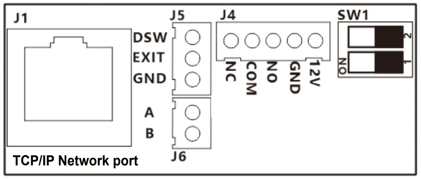
Interface description:
| Location | Function Description |
| J4 | Power and relay output interface |
| J5 | Exit button and door magnetic detection interface |
| J6 | 485 bus communication interface |
| J1 | LAN cable crystal head interface |
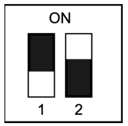
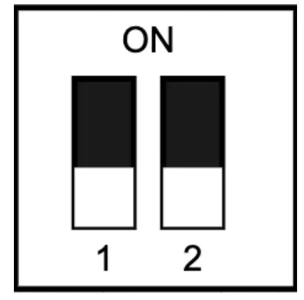
| SW1(0 means no dialing, 1 means dialing to ON) | Mode selection( 00:TCP/IP LAN networking,01:Offline) |
| Interface Name | Function Description |
| +12V | Power and relay output interface |
| GND | Exit button and door magnetic detection interface |
| NC | 485 bus communication interface |
| COM | LAN cable crystal head interface |
| NO | Relays normally open |
| EXIT | Exit key signal detection |
| DSW | Door magnet signal detection |
| 485A/B | 485 bus A/B interface |
System Wiring References
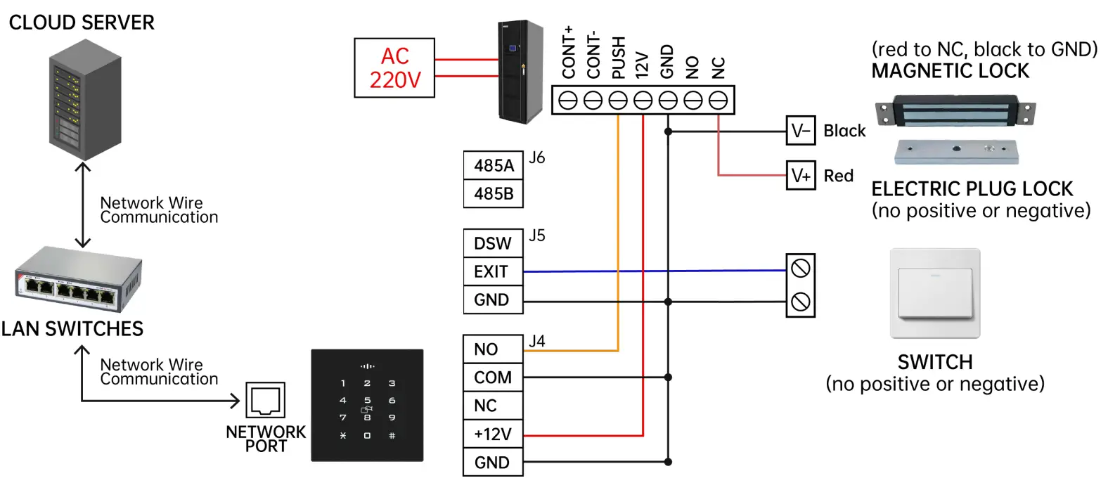
Wiegand Reader Installation Diagram
(a) Connect the signal line in the back of the read head device as shown in the figure below.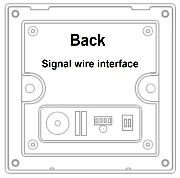
(b) Install the reading head device into the 86 box, (note that you need to use the embedded wall inside the depth of 50MM style 86 box), lock the screws to fix, as shown in the figure below.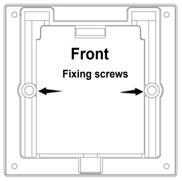
(c) Read the head panel and read the head body snap together, first from the upper snap down and then press the lower and bottom screw hole alignment; finally in the bottom of the anti-theft screw hole screwed on the countersunk head machine wire within the plum security screws fixed, as shown in the figure below.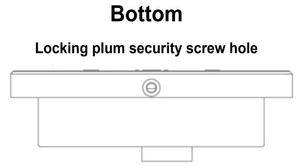
Multi-door Control Function Description
Operating mode selection
| Switch Setting | Indicates | Switch Setting | Indicates |
01 | Offline working | 00 | TCP/IP LAN networking |
Startup status
TCP/IP LAN networking : When the power is on, the blue LED flashes, indicating that it is looking for the network. When normally connected to the network, the buzzer “tick ~ tick” two short beeps, the LED red light is always on, indicating that the cloud access control has started normally; when 20 seconds later is not normally connected to the network, the buzzer “tick tick tick” three beeps, the LED red light is always on, indicating Connection network failure, the controller forced to start. After the controller is normally connected to the network, the LED green light will flash once every 20 seconds, indicating that there is data and the cloud platform interactive communication.
Offline working: When the power is started, the buzzer “beep” a short beep, the LED red light is always on, indicating that the cloud access control has started normally.
Unlock status
When the lock is opened legally, the buzzer of the controller and the reading head will be “beep” at the same time, accompanied by a green LED flashing once, and the corresponding relay will be jumped, which means that the lock is opened successfully; when the lock is opened illegally, the buzzer of the controller and the reading head will be “beep beep beep” three times at the same time, accompanied by a red LED flashing three times, which means that the lock is opened and failed.
Unlock method
The device can be unlocked by swipe card, remote APP, out door button, management center platform remote, cloud server platform remote, password (optional), and many other ways.
Multi-door Control Configuration
Management Center Add Controller
Connect the controller to the PC with a network cable, open the controller management software, and click Add Controller by Search. At this time, the management software can automatically search for the multi-door controllers connected to the LAN and assign them to the corresponding IP. Then configure the controller to the corresponding area. Click to confirm that the controller can be bound to the corresponding regional access control.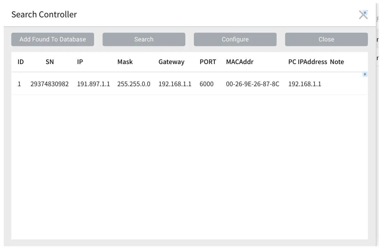
Add user and configure his permissions
In the management center, add users to configure the rights of the corresponding area controllers for them. After the configuration is completed, users can open the door in the room where these controllers are installed by swipe card, APP, password, etc. More detailed controller management and
Add User: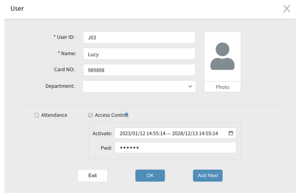
Configuration Permissions: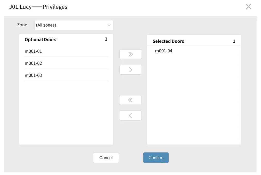
Remote Control Controller
Remotely open doors and view access records
After you open Trudian APP and log in the user you have added in the management center, the APP home page shows all the controllers that the current user can control. You can open the door remotely in APP, and you can also view all the door opening information recorded by the controller in APP.
View access records with APP: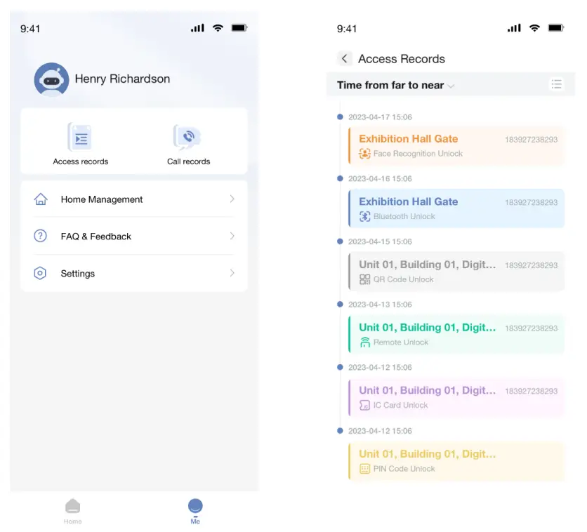
Open the door remotely with APP: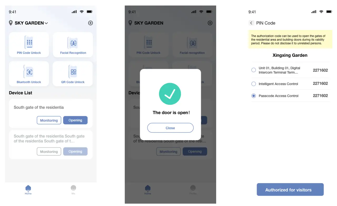
FCC Caution
This device complies with part 15 of the FCC Rules. Operation is subject to the following two conditions: (1) This device may not cause harmful interference, and (2) this device must accept any interference received, including interference that may cause undesired operation.
Any Changes or modifications not expressly approved by the party responsible for compliance could void the user’s authority to operate the equipment.
Note: This equipment has been tested and found to comply with the limits for a Class B digital device, pursuant to part 15 of the FCC Rules. These limits are designed to provide reasonable protection against harmful interference in a residential installation.
This equipment generates uses and can radiate radio frequency energy and, if not installed and used in accordance with the instructions, may cause harmful interference to radio communications. However, there is no guarantee that interference will not occur in a particular installation. If this equipment does cause harmful interference to radio or television reception, which can be determined by turning the equipment off and on, the user is encouraged to try to correct the interference by one or more of the following measures:
- Reorient or relocate the receiving antenna.
- Increase the separation between the equipment and receiver.
- Connect the equipment into an outlet on a circuit different from that to which the receiver is connected.
- Consult the dealer or an experienced radio/TV technician for help.
The device has been evaluated to meet general RF exposure requirement. The device can be used in portable exposure condition without restriction.
Customer Support
HQ Add: Farbell Technology Park,Yixian Road, Nanlang,
Cuiheng New District, Zhongshan City, Guangdong Province,
China. Zip Code:528451
Phone: +86 0760 – 23689666
E-mail: [email protected]
If the problem is not solved properly,please send the mail to:
[email protected]
www.trudian.com/en/