![]()
Performance LOAD® Cot Fastener System User Manual
![]() 6392
6392
Warning/Caution/Note Definition
The words WARNING, CAUTION, and NOTE carry special meanings and should be carefully reviewed.
WARNING
Alerts the reader about a situation which, if not avoided, could result in death or serious injury. It may also describe potential serious adverse reactions and safety hazards.
CAUTION
Alerts the reader of a potentially hazardous situation which, if not avoided, may result in minor or moderate injury to the user or patient or damage to the product or other property. This includes special care necessary for the safe and effective use of the device and the care necessary to avoid damage to a device that may occur as a result of use or misuse.
Note — Provides special information to make maintenance easier or important instructions clearer.
Introduction for service
This manual assists you with the service of your Stryker product. Read this manual to service this product. This manual does not address the operation of this product. See the Operations Manual for operating and use instructions. To view your Operations Manual online, see https://techweb.stryker.com/.
Expected service life
The Performance-LOAD cot fastener has a seven year expected service life under normal use conditions and with appropriate periodic maintenance.
Contact information
Contact Stryker Customer Service or Technical Support at: 1-800-327-0770.
Stryker Medical 3800 E. Centre Avenue Portage, MI 49002 USA
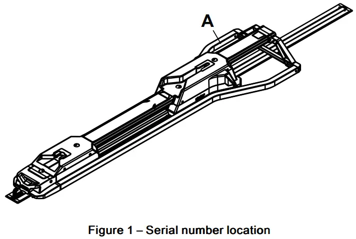
Note – The user and/or the patient should report any serious product-related incident to both the manufacturer and the Competent authority of the European Member State where the user and/or patient is established. To view your operations or maintenance manual online, see https://techweb.stryker.com/. Have the serial number (A) of your Stryker product available when calling Stryker Customer Service or Technical Support. Include the serial number in all written communication.
Serial number location
Preventive maintenance
Establish and follow a maintenance schedule and keep records of the maintenance activity. Remove product from service before you perform the preventive maintenance inspection. You may need to perform preventive maintenance checks more often based on your level of product usage. Service only by qualified personnel.
Every month
| Check | Routine |
| Foot end interface and head end interface | Clean debris |
Every three months
| Check | Routine |
| Loose fasteners | Replace if loose |
Every twelve months
| Check | Routine |
| All parts | Replace any worn parts, including covers, cot guides, and latch assembly, if necessary |
| Full functionality | See the Installation checklist in the Operations Manual |
Maintenance record
| Date | Maintenance operation performed | By | Hours |
Training record
| Training date | |||
| Trainee name | Basic training | Refresher update | Owner’s manual, in- service, formal class, etc. |
Troubleshooting
Inductive charging system does not charge the cot battery
Inductive charging system does not charge the cot battery when you load the cot into the fastener.
Note – Before you service the cot, disconnect the vehicle’s battery starting with the negative lead.
- Make sure that a SMRT Pak battery is used on the cot and that the cot is equipped with inductive charging hardware.
- Check for proper connection between the anchor-to-vehicle cable and the inductive primary board.
a. Check for 12.8V to 15.6V at the Performance-LOAD end of the anchor-to-vehicle cable (639000010135) connection.
b. If present, continue to step 3.
c. If not present, make sure that the vehicle meets the following electrical requirements: 12.8V – 15.6V, 15A fuse/breaker and two conductor 10 AWG cable. - Reattach the anchor-to-vehicle cable to the mating side of the inductive primary board.
- After making the connection, verify proper functionality:
a. Load a Power-PRO cot (with a SMRT Pak battery) into the fastener, check that the Power-PRO battery indicator is OFF prior to loading the cot into Performance-LOAD.
b. If the unit is functioning properly, the cot light panel orb will turn on within five seconds of being loaded into Performance-LOAD. The light indicates that the unit is receiving power and that the electrical installation is correct and complete.
c. If the light panel orb does not turn ON, check all connection points and replace the inductive coil and/or the primary board.
Service
Head end interface assembly replacement
Tools required:
- T27 Torx driver
- 1/4″ hex wrench
- Torque wrench (in-b)
Procedure:
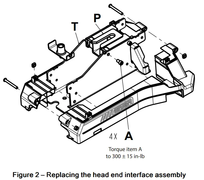
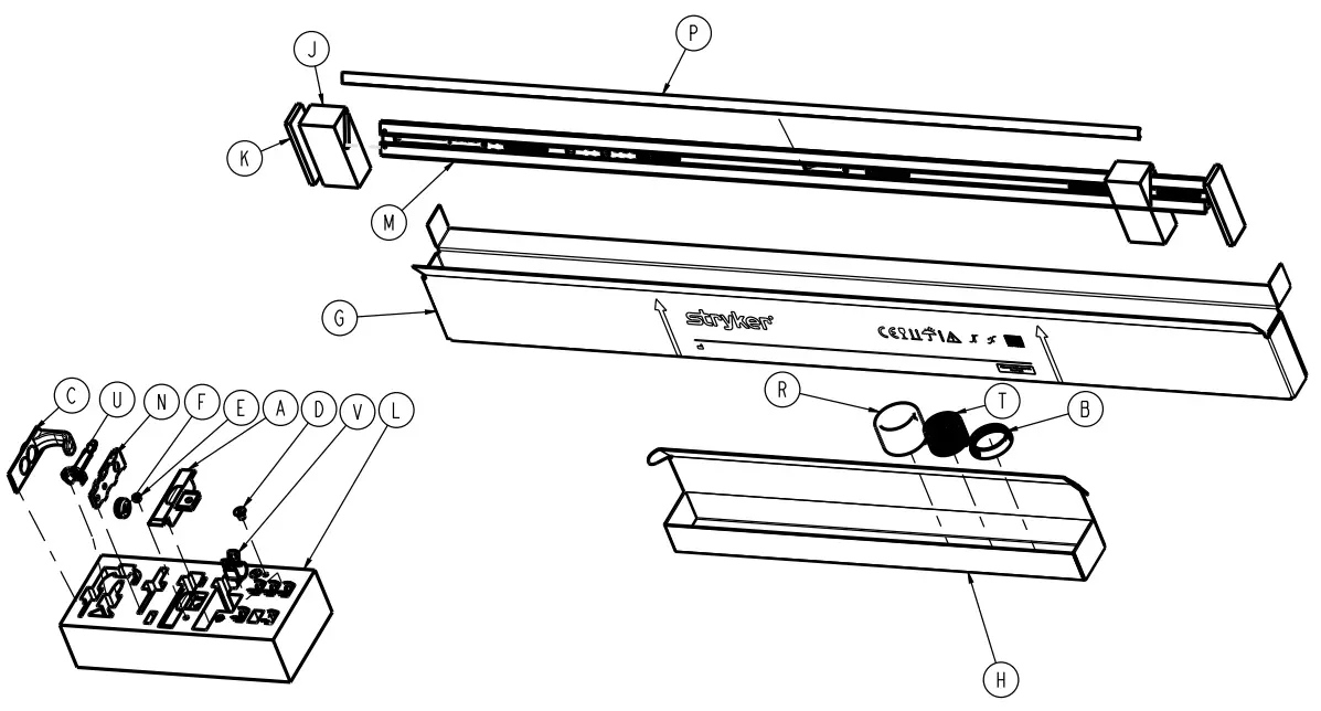
- Using a T27 Torx driver, remove the four screws that secure the head end top cover to the head end bottom covers.
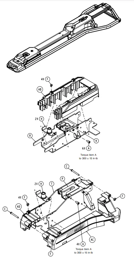
Save the screws. - Using a 1/4″ hex wrench, remove the four screws (A) that secure the head end interface assembly (P) to the head end weldment (T) (Figure 2). Save the screws.
Note – Torque item (A) to 300 + 15 in-Ib.
- Remove and discard the head end interface assembly.
- Reverse steps to reinstall.
- Verify proper operation before you return the product to service.
Foot end interface assembly replacement
Tools required:
- 727 Torx driver
- 1/4″ hex wrench
- Torque wrench (in-b)
Procedure:
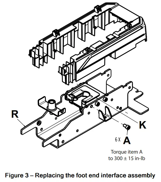
- Using a T27 Torx driver, remove the six screws that secure the foot end top cover to the foot end bottom cover. Save the screws.
- Using a 1/4″ hex wrench, remove the six screws (A) that secure the foot end interface assembly (K) to the foot end weldment (R) (Figure 3). Save the screws.
Note – Torque item (A) to 300 + 15 in-Ib.
- Remove the foot end interface from the lower release link by sliding it toward the head end. Discard the foot end interface.
- Reverse steps to reinstall.
- Verify proper operation before you retum the product to service.
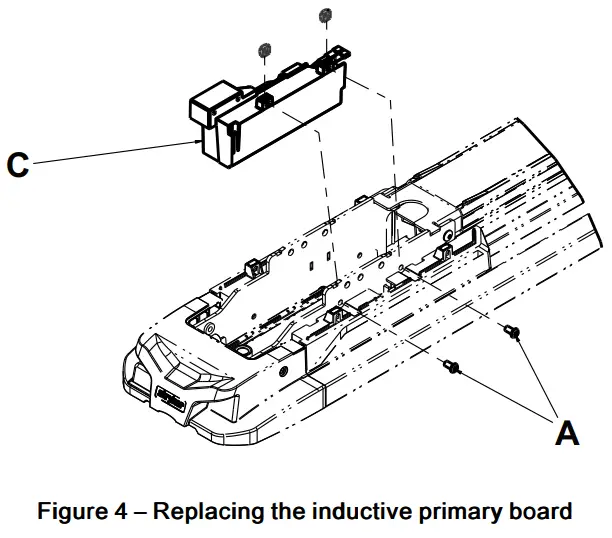
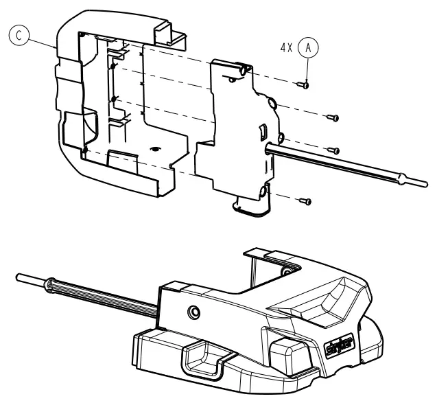
Inductive primary board replacement (optional)
Tools required:
- T27 Torx driver
Procedure:
- Unsnap the floor plate cover to gain access to the electrical connection.
- Disconnect the red and black wires from the cable harness.
- Using a T27 Torx driver, remove the six screws that secure the foot end top cover to the foot end bottom cover. Save the screws.
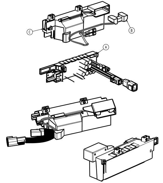
- Using a T27 Torx driver, remove the two screws (A) that secure the inductive charging assembly (C) to the foot end weldment (Figure 4). Save the screws.
- Remove the inductive charging assembly.
- Remove the inductive primary board from the charging enclosure. Discard the inductive primary board.
Note – Do not dispose of as unsorted municipal waste. Refer to your local distributor for return or collection systems available in your country. - Reverse steps to reinstall.
- Verify proper operation before you return the product to service.
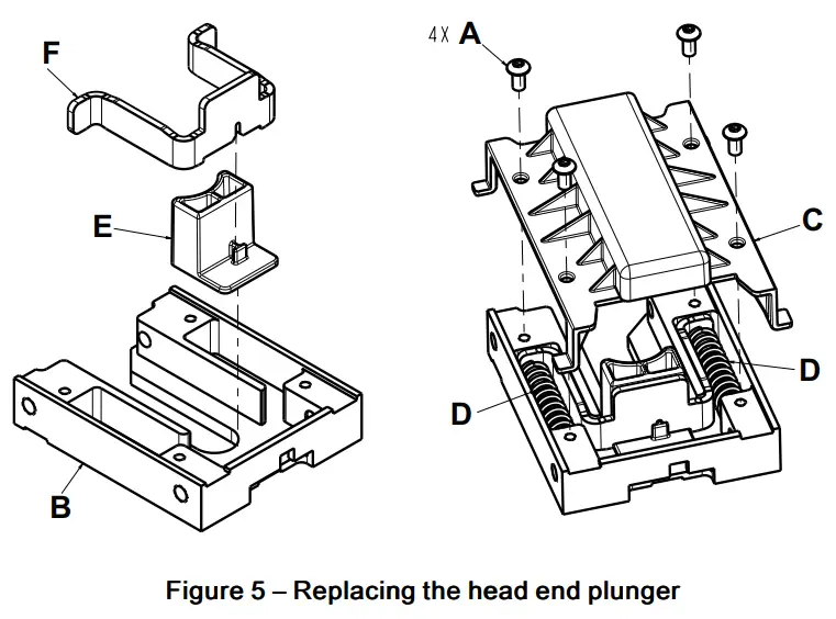
Head end plunger replacement
Tools required:
- 727 Torx driver
Procedure:
- Remove the head end interface assembly (See Head end interface assembly replacement (page 7)).
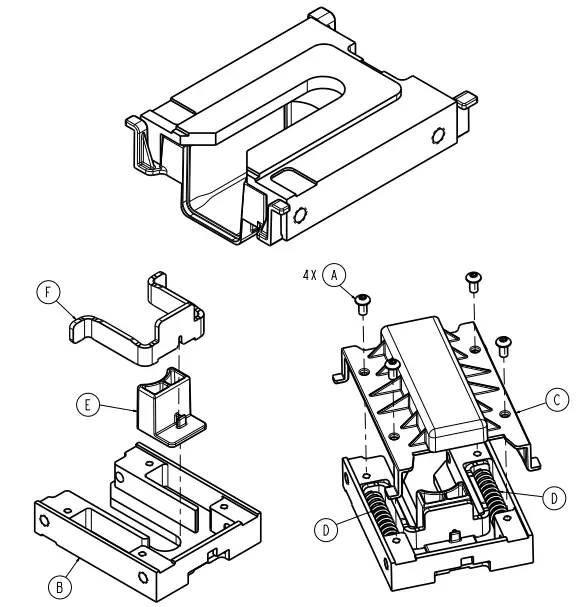
- Using a T27 Torx driver, remove the four screws (A) that secure the pin enclosure (C) to the head end interface (B) (Figure 5). Save the screws.
- Remove and save the two plunger springs (D) (Figure 5).
- Remove and save the plunger bracket (F) (Figure 5).
- Remove and discard the plunger (E) (Figure 5).

- Reverse steps to reinstall.
- Verify proper operation before you retum the product to service.
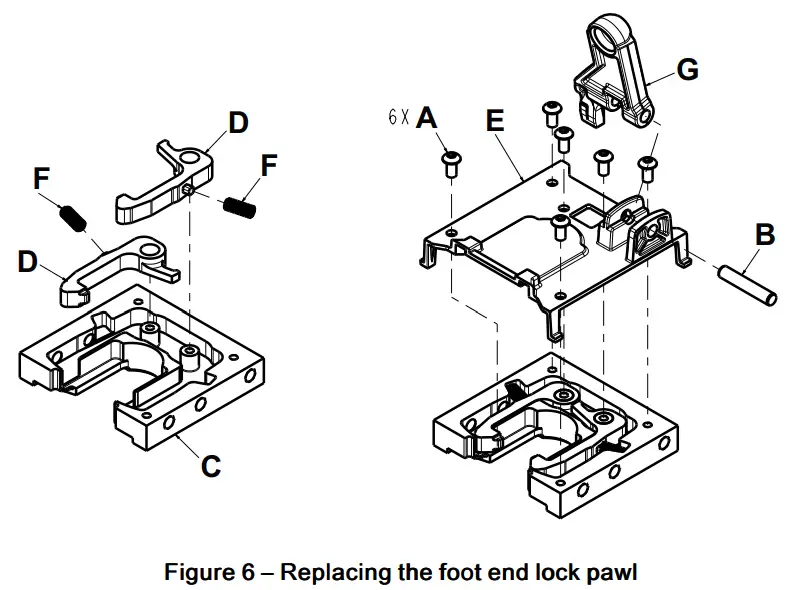
Foot end lock pawl replacement
Tools required:
- 725 Torx driver
- 1/8″ punch
Procedure:
- Remove the foot end interface assembly (see Foot end interface assembly replacement (page 7)).
- Using a 1/8″ punch, push the dowel pin (B) out of the release latch arm (G) (Figure 6). Save the dowel pin.
- Using a T25 Torx driver, remove the six screws (A) that secure the pivot bracket to the foot end interface (C) (Figure 6).
Save the screws. - Remove and discard the lock pawl (D) (Figure 6).
Note – Make sure that the pawl spring (F) remains in place when you remove the lock pawl.
- Reverse steps to reinstall.
Note – Fully insert the dowel pin during reassembly. - Verify proper operation before you return the product to service.
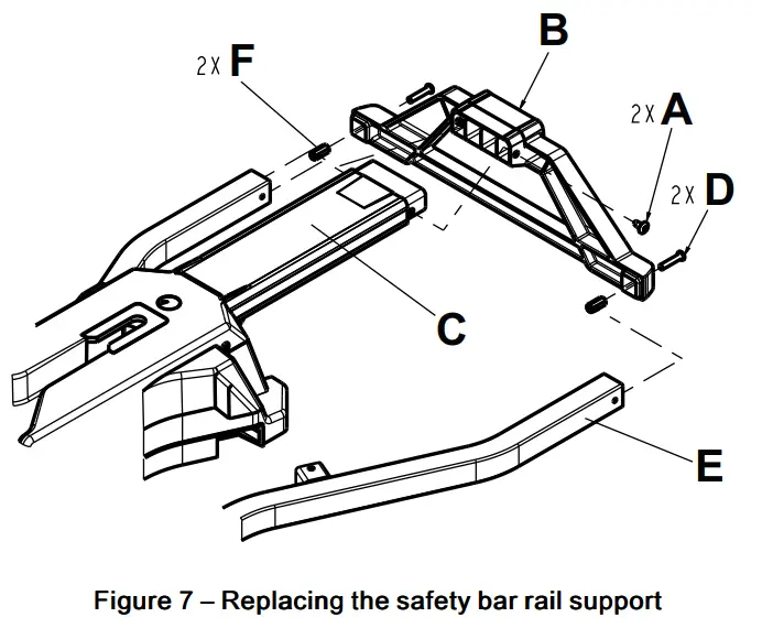
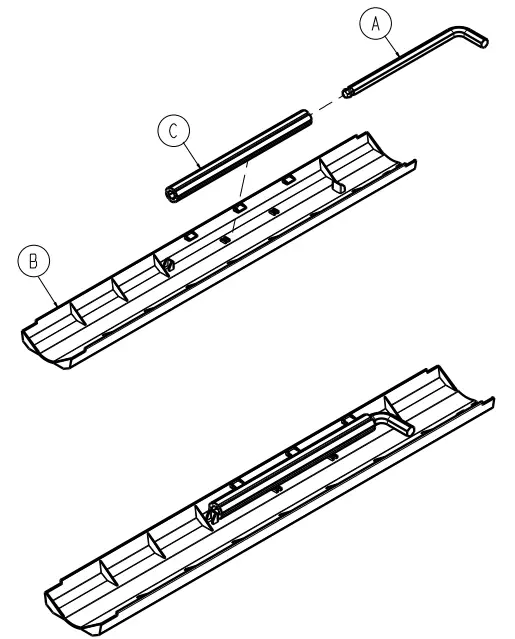
Safety bar rail support replacement
Tools required:
- 727 Torx driver
Procedure:
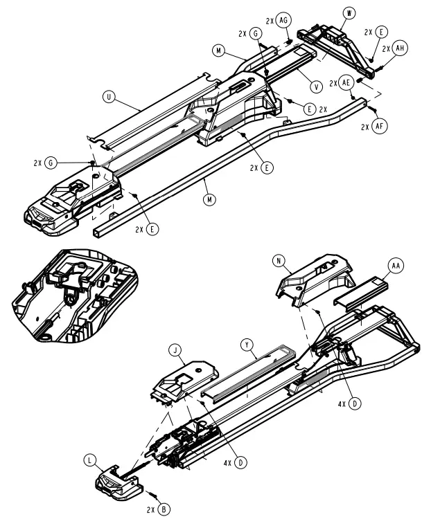
- Using a T27 Torx driver, remove the two screws (A) that secure the safety bar rail support (B) to the safety bar rail (C) (Figure 7). Save the screws.

- Using a T27 Torx driver, remove the two screws (D) that secure the safety bar rail support (B) to the guide rails (E) (Figure 7). Save the screws. Discard the safety bar rail support.
- Reverse steps to reinstall.
Note – Make sure that the two hex couplers (F) are centered in the guide rails (E) before you reinstall (Figure 7). - Verify proper operation before you return the product to service.
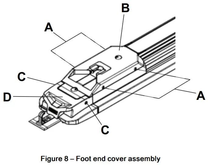
Foot end cover assembly replacement
Tools required:
- T27 Torx driver
- 15/16″ hex wrench
- 3/8″ Allen wrench
Procedure:
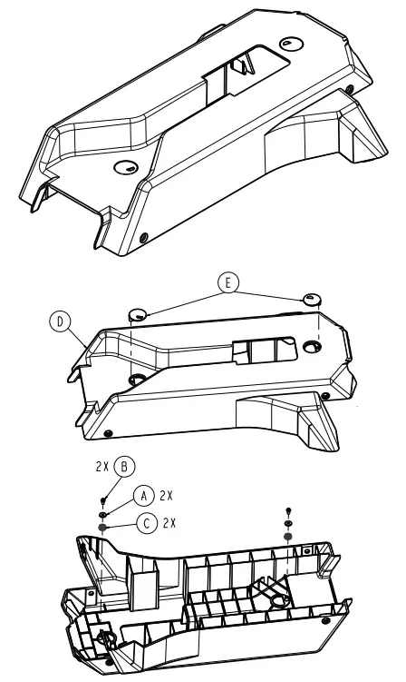
- Using a T27 Torx driver, remove the four socket head cap screws (A) that secure the foot end cover assembly (B) to the transfer (Figure 8). Save the screws.
- Using a T27 Torx driver, remove the two button head cap screws (C) that secure the foot end cover assembly to the foot end nose assembly (D) (Figure 8). Save the screws.
- Remove the foot end cover assembly by sliding it toward the head end of the vehicle patient compartment. Discard the foot end cover assembly.
- Reverse steps 1-3 to reinstall the foot end cover assembly.

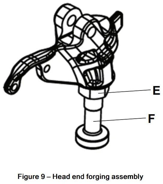
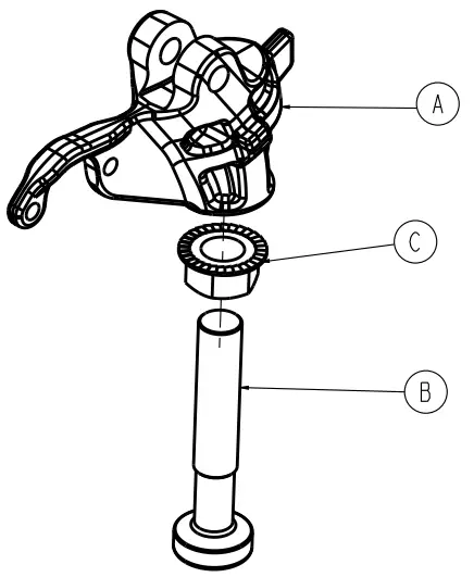
- Using a 15/16″ hex wrench, loosen the locknut (E) that secures the pin (F) to the head end forging assembly (Figure 9).

- Using a 3/8″ Allen wrench, adjust the pin so there is maximum clearance between the foot end cover assembly during loading and unloading.
Note – The pin must lock into the head end of the fastener while loaded. - Using a 15/16″ hex wrench, tighten the locknut that secures the pin to the head end forging assembly.
- Verify proper operation before you return the product to service.
Note – You must repair the cot and Performance-LOAD to avoid recurring damage to the foot end cover assembly.
Performance-LOAD assembly
6392-001-010 Rev AA (Reference only)
| Item | Number | Name | Quantity |
| A | 0004-270-000 | Socket head cap screw | 10 |
| B | 0004-376-000 | Button head cap screw | 2 |
| C | 0004-387-000 | Button head cap screw | 2 |
| D | 0004-589-000 | Button head cap screw | 8 |
| E | 0007-052-000 | Truss head Torx screw | 8 |
| F | 0015-096-000 | Square nut | 10 |
| G | 0023-350-000 | Pan head thread-cutting tapping screw | 4 |
| H | 6392-001-012 | Floor plate bolt assembly (page 17) | 4 |
| J | 6392-001-021 | Foot end cover assembly (page 20) | 1 |
| K | 6392-001-022 | Foot end interface assembly (page 21) | 1 |
| L | 6392-001-023 | Foot end nose assembly (page 22) | 1 |
| M | 6.39201E+11 | Weldment, guide rail | 2 |
| N | 6392-001-031 | Head end cover assembly (page 24) | 1 |
| P | 6392-001-032 | Head end interface assembly (page 25) | 1 |
| R | 6392-001-052 | Weldment, foot end | 1 |
| T | 6392-001-053 | Weldment, head end | 1 |
| U | 6392-001-102 | Safety bar rail, long | 1 |
| V | 6392-001-103 | Safety bar rail, short | 1 |
| W | 6392-001-104 | Safety bar rail support | 1 |
| Y | 6392-001-105 | Safety bar rail cover, long | 1 |
| AA | 6392-001-106 | Safety bar rail cover, short | 1 |
| AB | 6392-001-208 | Foot end cover, bottom | 1 |
| AC | 6392-001-303 | Head end cover, patient left | 1 |
| AD | 6392-001-304 | Head end cover, patient right | 1 |
| AE | 0016-003-000 | Nylon hex nut | 2 |
| AF | 0004-171-000 | Button head cap screw | 2 |
| AG | 6.392E+11 | Hex coupler | 2 |
| AH | 0004-198-000 | Button head cap screw | 2 |
Center cover assembly
6392-001-011 Rev A (Reference only)
| Item | Number | Name | Quantity |
| A | 0057-011-000 | 3/8” hex wrench, ball end | 1 |
| B | 6392-001-403 | Floor plate cover | 1 |
| C | 6392-001-406 | Removal tool extension | 1 |
Floor plate bolt assembly
6392-001-012 Rev A (Reference only)
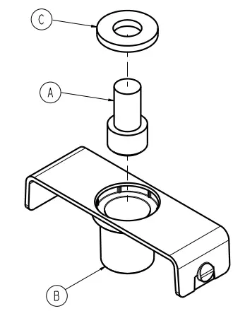
| Item | Number | Name | Quantity |
| A | 0004-910-000 | Socket head cap screw | 1 |
| B | 6392-001-142 | Floor plate bolt holder | 1 |
| C | 6392-001-143 | Washer, bolt holder | 1 |
Install kit assembly
6392-001-014 Rev A (Reference only)
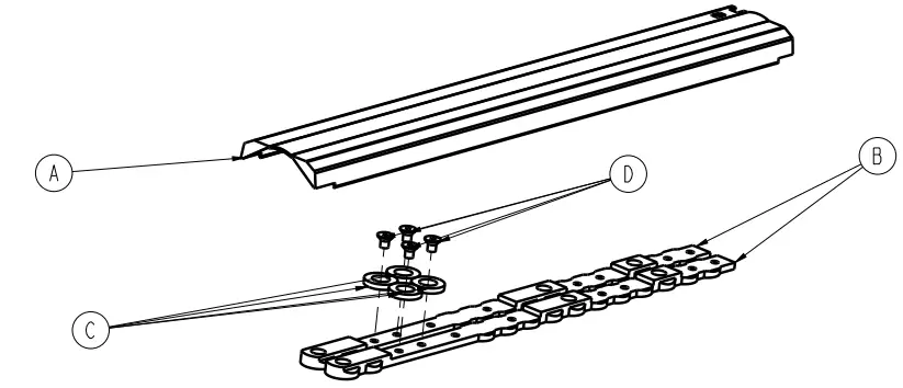
| Item | Number | Name | Quantity |
| A | 6392-001-011 | Center cover assembly | 1 |
| B | 6392-001-400 | Cleat | 2 |
| C | 6392-001-401 | Cleat locator washer | 4 |
| D | 0001-194-000 | Flat head cap screw | 4 |
Inductive charging option
6392-001-015 Rev AA (Reference only)
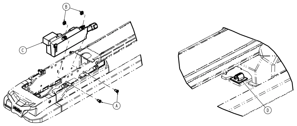
| Item | Number | Name | Quantity |
| A | 0004-589-000 | Button head cap screw | 2 |
| B | 0015-096-000 | Square nut | 2 |
| C | 639200010041 | Inductive charging assembly (page 26) | 1 |
| D | 0058-394-000 | Cable clip | 1 |
Foot end cover assembly
6392-001-021 Rev A (Reference only)
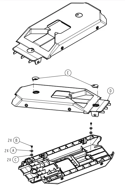
| Item | Number | Name | Quantity |
| A | 0011-642-000 | Plain washer | 2 |
| B | 0023-349-000 | Pan head thread forming screw | 2 |
| C | 0038-905-000 | Spin cap spring | 2 |
| D | 6392-001-108 | Top cover, foot end | 1 |
| E | 6392-001-309 | Spin cap | 2 |
Foot end interface assembly
6392-001-022 Rev A (Reference only)
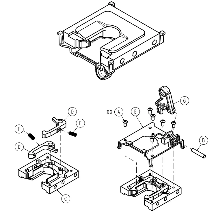
| Item | Number | Name | Quantity |
| A | 0004-442-000 | Button head cap screw | 6 |
| B | 0026-556-000 | Dowel pin | 1 |
| C | 6392-001-202 | Interface, foot end | 1 |
| D | 6392-001-250 | Lock pawl, foot end | 2 |
| E | 6392-001-251 | Pivot bracket, foot end interface | 1 |
| F | 6392-001-252 | Pawl spring | 2 |
| G | 6392-001-257 | Release latch link arm | 1 |
Foot end nose assembly
6392-001-023 Rev A (Reference only)
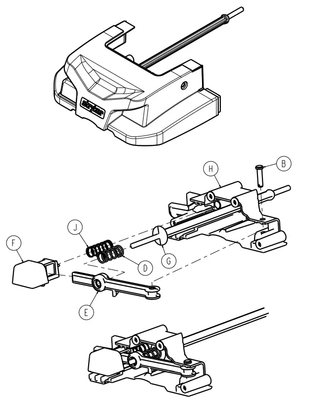
| Item | Number | Name | Quantity |
| A | 0023-167-000 | Pan head thread forming screw | 4 |
| B | 0026-316-000 | Clevis pin | 1 |
| C | 6392-001-205 | Nose cover | 1 |
| D | 6392-001-253 | Thick release spring | 1 |
| E | 6392-001-254 | Release pivot arm | 1 |
| F | 6392-001-255 | Release button | 1 |
| G | 6392-001-256 | Release lower link | 1 |
| H | 6392-001-258 | Release housing | 1 |
| J | 6392-001-259 | Thin long release spring | 1 |
Head end cover assembly
6392-001-031 Rev A (Reference only)
| Item | Number | Name | Quantity |
| A | 0011-642-000 | Plain washer | 2 |
| B | 0023-349-000 | Pan head thread forming screw | 2 |
| C | 0038-905-000 | Spin can spring | 2 |
| D | 6392-001-109 | Head end top cover | 1 |
| E | 6392-001-309 | Spin cap | 2 |
Head end interface assembly
6392-001-032 Rev A (Reference only)
| Item | Number | Name | Quantity |
| A | 0004-442-000 | Button head cap screw | 4 |
| B | 6392-001-302 | Head end interface | 1 |
| C | 6392-001-305 | Head end pin closure | 1 |
| D | 6392-001-306 | Plunger spring | 2 |
| E | 6392-001-307 | Head end plunger | 1 |
| F | 6392-001-308 | Head end plunger bracket | 1 |
Inductive charging assembly
639200010041 Rev AA (Reference only)
| Item | Number | Name | Quantity |
| A | 639002010147 | Inductive primary board | 1 |
| B | 6390-001-133 | Anchor primary coil | 1 |
| C | 6392-001-150 | Inductive charging enclosure | 1 |
Head end hitch assembly
6392-001-061 Rev A (Reference only)
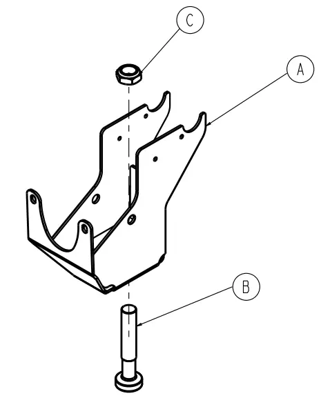
| Item | Number | Name | Quantity |
| A | 6392-001-054 | Head end hitch weldment | 1 |
| B | 6392-001-500 | Head end hitch pin | 1 |
| C | 0016-019-000 | Nylock hex nut | 1 |
Head end forging assembly
6392-001-062 Rev A (Reference only)
| Item | Number | Name | Quantity |
| A | 6392-001-510 | Machined forging | 1 |
| B | 6392-001-500 | Head end hitch pin | 1 |
| C | 0016-323-000 | Hex flange serrated lock nut | 1 |
Floor plate, assembly kit
639207000001 Rev AA (Reference only)
| Item | Number | Name | Quantity |
| A | 639000010111 | Floor plate end cap, machined | 1 |
| B | 639000010135 | Anchor-to-vehicle cable | 1 |
| C | 639000010148 | PPoowweerr–LLOOAADD safety hook | 1 |
| D | 0001-194-000 | Flat head cap screw | 2 |
| E | 0021-197-000 | Set screw | 2 |
| F | 0037-247-000 | Rubber grommet | 1 |
| G | 0054-200-372 | Floor plate/wheel guide shipping box | 1 |
| H | 0054-200-375 | Component shipping box | 1 |
| J | 0054-200-380 | Floor plate shipping foam | 2 |
| K | 0054-200-383 | Wheel guide end cap | 2 |
| L | 0054-401-003 | Floor plate foam pack | 1 |
| M | 6390-001-107 | Floor plate | 1 |
| N | 6390-101-108 | Floor plate attachment bracket | 1 |
| P | 6390-001-109 | Floor plate cap | 1 |
| R | 6390-001-153 | Wire protection loom, under ambulance | 1 |
| T | 6390-001-170 | Drain tube | 1 |
| U | 6390-001-183 | Drain tube, floor plate | 1 |
| V | 6390-001-202 | Clamp, rubber coated, p style | 6 |
| W | 6390-009-044 | Model 6390 wiring update memo (not shown) | 1 |
| Y | 6390-109-020 | Floor plate installation instructions (not shown) | 1 |
EMC information
| Guidance and manufacturer’s declaration – electromagnetic emissions | ||
| Performance-LOAD is intended for use in the electromagnetic environment specified below. The customer or the user of Performance-LOAD should assure that it is used in such an environment. | ||
| Emissions test | Compliance | Electromagnetic environment |
| RF Emissions CISPR 11 | Group 2 | The Performance-LOAD system must emit electromagnetic energy in order to perform its intended function. Nearby electronic equipment may be affected. |
| RF Emissions CISPR 11 | Class A | The Performance-LOAD system is suitable for use in all establishments other than domestic and those directly connected to the public low-voltage power supply network that supplies buildings used for domestic purposes. |
Recommended separations distances between portable and mobile RF communications equipment and Performance-LOAD
Performance-LOAD is intended for use in an electromagnetic environment in which radiated RF disturbances are controlled. The customer or the user of Performance-LOAD can help prevent electromagnetic interferences by maintaining a minimum distance between portable and mobile RF communications equipment (transmitters) and Performance-LOAD as recommended below, according to the maximum output power of the communications equipment.
| Rated maximum output power of transmitter W | Separation distance according to frequency of transmitter m | ||
| 150 kHz to 80 MHz d=(1.2) (JP) | 80 MHz to 800 MHz d=(.18) (VP) | 800 MHz to 2.5 GHz d=(.35) (VP) | |
| 0.01 | 0.12 | 0.035 | 0.07 |
| 0.1 | 0.38 | 0.11 | 0.22 |
| 1 | 1. | 0.35 | 0.7 |
| 10 | 4. | 1. | 2. |
| 100 | 12 | 4. | 7 |
For transmitters rated at a maximum output power not listed above, the recommended separation distance d in meters (m) can be estimated using the equation applicable to the frequency of the transmitter, where P is the maximum output power rating of the transmitter in watts (W) according to the transmitter manufacturer. Note 1: At 80 MHz and 800 MHz, the separation distance for the higher frequency range applies. Note 2: These guidelines may not apply in all situations. Electromagnetic propagation is affected by absorption and reflection from structures, objects, and people.
For transmitters rated at a maximum output power not listed above, the recommended separation distance d in meters (m) can be estimated using the equation applicable to the frequency of the transmitter, where P is the maximum output power rating of the transmitter in watts (W) according to the transmitter manufacturer. Note 1: At 80 MHz and 800 MHz, the separation distance for the higher frequency range applies. Note 2: These guidelines may not apply in all situations.
Electromagnetic propagation is affected by absorption and reflection from structures, objects, and people.
| Immunity test | EN/IEC 80801 test level | Compliance level | Electromagnetic environmeM-guidance |
| Guidance and manufacturers declaration – electromagnetic immunity | |||
| Electrostatic discharge (ESD) IEC 61000-4-2 | +8 kV contact +15 IN air — | +8 W contact +15 kV air — | Floors should be wood. concrete, or ceramic tile. If floors are covered with synthetic material, the relative humidity should be at least 30%. |
| Power frequency (50/60 Hz) magnetic field IEC 61000-4-8 | 30 Aim | 30 Alm | Power frequency magnetic fields should be at levels characteristic of a typical location in a typical commercial or hospital environment. |
| Note: UT is the a.c. mains voltage before applications of the test level. | |||
| Conducted RF IEC 61000-4-6 Radiated RF IEC 61000-4-3 | 3 Vrms 150 kHz to 80 MHz 10 Vim 80 MHz to 2.5 GHz | 3 Vrms 10 V/m | Portable and mobile RF communications equipment should be used no closer to any part of Performance-LOAD. including cables. than the recommended separation distance calculated from the equation appropriate for the frequency of the transmitter. Recommended separation distance D=(.35) N P) 80 MHz to 800 MHz D(0.70) (.’P) 800 MHz to 2.5 GHz where Pis the maxinum output power rating of the transmitter in watts (W) according to the transmitter manufacturer and d is the recommended separation distance in meters (m). Field strengths from fixed RF transmitters. as determined by an electromagnetic site’ should be less than the oompliance level in each frequency range’ Interference may occur in the vicinity of equipment marked with the following symbol: |
Guidance and manufacturer’s declaration – electromagnetic immunity
Note 1: At 80 MHz and 800 MHz, the higher frequency range applies. Note 2: These guidelines may not apply in all situations. Electromagnetic propagation is affected by absorption and reflection from structures, objects, and people.
a Field strengths from fixed transmitters, such as base stations for radio (cellular/cordless) telephones and land mobile radios, amateur radio, AM and FM radio broadcast, and TV broadcast cannot be predicted theoretically with accuracy. To assess the electromagnetic environment due to fixed RF transmitters, an electromagnetic site survey should be considered. If the measured field strength in the location in which Performance-LOAD is used exceeds the applicable RF compliance level above, the Performance-LOAD system should be observed to verify normal operation. If abnormal performance is observed, additional measures may be necessary, such as reorienting or relocating Performance-LOAD.
b Over the frequency range 150 kHz to 80 MHz, field strengths should be less than 3 V/m.
![]()
![]() Stryker Medical
Stryker Medical
3800 E. Centre Avenue
Portage, MI 49002
USA
6392-209-002 Rev AA.0
WCR: AD.6


