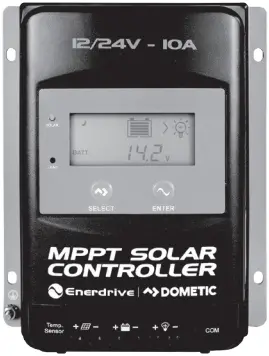
MPPT SOLAR
CONTROLLER
Owner’s Manual
Rev: 1.3 (2022)
EN43510 – MPPT Solar Controller 12/24V – 10Amp
EN43520 – MPPT Solar Controller 12/24V – 20Amp
EN43530 – MPPT Solar Controller 12/24V – 30Amp
EN43540 – MPPT Solar Controller 12/24V – 40Amp
Please Keep This Manual For Future Reference
For safe and optimum performance, the MPPT Solar Controller must be used correctly.
Carefully read and follow all instructions and guidelines in this manual and give special attention to the CAUTION and WARNING statements.
Disclaimer
While every precaution has been taken to ensure the accuracy of the contents of this manual, Enerdrive assumes no responsibility for errors or omissions. Note as well that specifications and product functionality may change without notice.
Important
Please be sure to read and save the entire manual before using your MPPT Solar Controller.
Misuse may result in damage to the unit and/or cause harm or serious injury. Read manual in its entirety before using the unit and save manual for future reference.
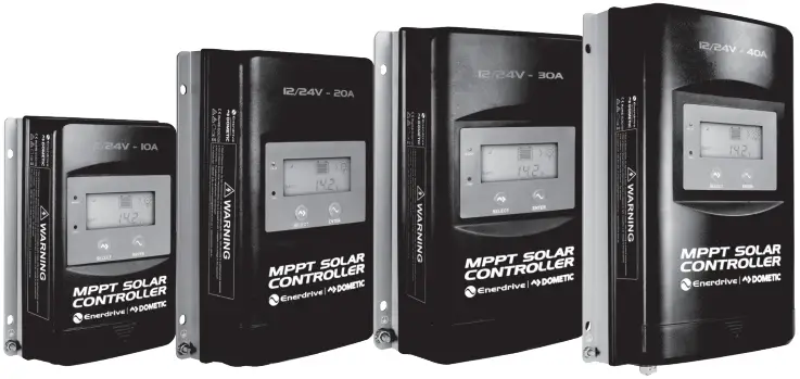
Product Numbers – MPPT Solar Controller Series
| EN43510 | MPPT Solar Controller 12/24V-10Amp |
| EN43520 | MPPT Solar Controller 12/24V-20Amp |
| EN43530 | MPPT Solar Controller 12/24V-30Amp |
| EN43540 | MPPT Solar Controller 12/24V-40Amp |
MPPT Solar Controller Owners Manual Rev. 1.3. This Manual is applicable to all units with part numbers prefix EN435XXX (EN43510, EN43520, EN43530, EN43540).
Service Contact Information
Dometic Power & Control (Enerdrive) Pty Ltd
PO Box 9159, Wynnum Plaza, QLD 4178
Ph: 1300 851 535 / Fax: 07 3390 6911
Email: [email protected] | Web: www.enerdrive.com.au
Notice of Copyright
Enerdrive MPPT Solar Controller owner’s manual © 2022 Dometic Power & Control (Enerdrive) Pty Ltd. All rights reserved. No part of this document may be reproduced in any form or disclosed to third parties without the express written permission of Dometic Power & Control (Enerdrive) Pty Ltd. Enerdrive reserves the right to revise this document and to periodically make changes to the content hereof without obligation or organisation of such revisions or changes, unless required to do so by prior arrangement.
Exclusions For Documentation And Product Usage
- Unless specifically agreed to in writing, Dometic Power & Control (Enerdrive) Pty Ltd: makes no warranty as to the accuracy, sufficiency or suitability of any technical or other information provided in its manuals or other documentation.
- Assumes no responsibility or liability for losses, damages, costs or expenses, whether special, direct, indirect, consequential or incidental, which might arise out of the use of such information. The use of any such information will be entirely at the user’s risk.
- Reminds you that if this manual is in any language other than English although steps have been taken to maintain the accuracy of the translation, the accuracy cannot be guaranteed.
- Makes no warranty, either expressed or implied, including but not limited to any implied warranties of merchantability or fitness for a particular purpose, regarding these Enerdrive products and makes such Enerdrive products available solely on an “as is” basis.
- Shall in no event be liable to anyone for special, collateral, incidental, or consequential damages in connection with or arising out of purchase or use of these Enerdrive products. The sole and exclusive liability to Enerdrive, regardless of the form of action, shall not exceed the purchase price of the Enerdrive products described here in.
1. GENERAL INFORMATION
1.1 OVERVIEW
The Enerdrive MPPT Solar Controllers adopt the advanced Maximum Power Point Tracking control algorithm. It can minimise the maximum power point loss rate and loss time, quickly track the maximum power point (MPP) of the PV array and obtain the maximum energy from the solar array under any conditions; and it can increase the ratio of energy utilization in the solar system by up to 20%-30% compared with PWM charging method. IP33 Ingress protection and isolated RS485 design further improve the controller’s reliability and meet the different application requirements.
Enerdrive MPPT Solar Controllers include self-adaptive three-stage charging mode based on digital control circuit, which can effectively prolong the lifespan of batteries and significantly improve the system performance. It also has comprehensive electronic protection for overcharge, over discharge and PV/ battery reverse polarity. This controller is suitable for RV, Marine, Remote Off Grid monitoring and many other applications.
FEATURES
- CE certification(LVD EN/IEC62109,EMC EN61000-6-1/3)
- LCD display
- Advanced MPPT technology & ultra-fast tracking speed with efficiency up to 99.5%
- Maximum DC/DC transfer efficiency is as high as 98.6%.
- Advanced MPPT control algorithm to minimize the MPP lost rate and lost time
- Accurate recognition and tracking of multi-peaks maximum power point
- Wide MPP operating voltage range
- Support lead-acid and lithium batteries; voltage parameters can be set on the controller
- Limit charging power & current over rated value
- Real-time energy statistics function
- Power reduction automatically over temperature value
- Multiple load work modes
- Comprehensive electronic protection
- Isolated RS485 with 5V/200mA protected output for no power devices, with Modbus protocol
- IP33 Ingress protection
For battery types other than Lithium, the BCV, FCV, LVD, and LVR, users can modify them on the controller by setting the battery type to “USE.”
1.2 CHARACTERISTICS
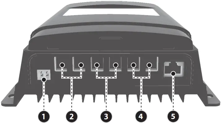
Figure 1 – Product Characteristics
- RTS* Port
- PV Terminals
- Battery Terminals
- Load Terminals
- RS485 Communication Port
*If the temperature sensor is short circuited or damaged, the controller will charge/discharge according to the voltage set point at the default temperature setting of 25°C (no temperature compensation).
2. INSTALLATION
2.1 CAUTION
- Please read the entire installation instructions to get familiar with the installation steps before installation.
- Be very careful when installing the batteries, especially flooded lead-acid battery. Please wear eye protection and have fresh water available to wash and clean any contact with battery acid.
- Keep the battery away from any metal objects, which may cause short circuit of the battery.
- Explosive battery gases may come out from the battery during charging, so make sure ventilation condition is good – ensure proper ventilation is present.
- Ventilation is highly recommended if mounted in an enclosure. Never install the controller in a sealed enclosure with flooded batteries! Battery fumes from vented batteries will corrode and destroy the controller circuits.
- Loose power connections and corroded wires may result in high heat that can melt wire insulation, burn surrounding materials, or even cause fire. Ensure tight connections and use cable clamps to secure cables and prevent them from swaying in mobile applications.
- The controller can work with lead-acid battery and lithium battery within its specifications.
- Multiple same models of controllers can be installed in parallel on the same battery bank to achieve higher charging current. Each controller must have its own solar panel(s).
- Installation must be completed in accordance with applicable local standards.
2.2 PV ARRAY REQUIREMENTS
(1) MAXIMUM PV ARRAY POWER
(1) - Enerdrive MPPT controllers include charge current limiting allowing the controller to limit the charging current if the incoming PV array exceeds the controllers maximum charging output. This allows the controller to protect internal charging components avoiding damage from oversized PV arrays. This function also allows for overdriving of the solar controller increasing the amount of time the controller is receiving its peak harvest from the PV array.
MPPT controller overdrive –
*Note: The recommended maximum solar wattage input for the EN43540 controller is 600 watts 12V. You can however “overdrive” the MPPT controller. Please note that doing this is partially an economic decision. You can install more power than the controller can use and this will contribute to better power availability. Enerdrive suggest a total maximum overdrive of 20% (total 720W). On cloudy (or intermittent sunny) days there will be little or no power shaving and the extra power will serve the battery well with more energy harvest earlier and later in the day.*
Peak Sun Hours
EN43540 Maximum Solar Harvest on a 12V System
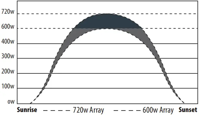
According to “Peak Sun Hours diagrams”, if the power of PV array exceeds the rated charging power of the controller, then the charging time as per the rated power will be prolonged, so that more energy can be obtained for charging the battery. However, in the practical application, the maximum power of PV array shall be not greater than 1.2x the rated charging power of controller. If the maximum power of PV array exceeds the rated charging power of the controller too much, it will not only cause the waste of PV modules, but also increase the open-circuit voltage of PV array due to the influence of environmental temperature, which may make the probability of damage to the controller rise. Therefore, it is very important to configure the system correctly. Excess Solar above the 1.2x rating is best suited to a higher rated controller, or split the array through multiple controllers.
![]() CAUTION
CAUTION
When the PV modules connect in series, the open circuit voltage of the PV array must not exceed 92V at 25°C environment temperature.
For the recommended maximum power of PV array for this controller, please refer to the table below:
| MODEL | RATED CHARGE CURRENT | MAX. PV ARRAY POWER RECOMMENDED | MAX. PV ARRAY POWER ALLOWED | MAX. PV OPEN CIRCUIT VOLTAGE |
| EN43510 | 10A | 150W/12V 300W/24V | 180W/12V 360W/24V | 92V¹ |
| EN43520 | 20A | 300W/12V 600W/24V | 360W/12V 720W/24V | |
| EN43530 | 30A | 450W/12V 900W/24V | 540W/12V 1080W/24V | |
| EN43540 | 40A | 600W/12V 1200W/24V | 720W/12V 1440W/24V |
¹ 92v at 25°C environment temperature
2.3 WIRE SIZE
The wiring and installation methods must conform to all national and local electrical code requirements.
| MODEL | MAX. PV INPUT CURRENT | MAX. PV WIRE SIZE* |
| EN43510 | 10A | 4MM²/12AWG |
| EN43520 | 20A | 6MM²/10AWG |
| EN43530 | 30A | 10MM²/8AWG |
| EN43540 | 40A | 13.2MM²/6AWG |
BATTERY AND LOAD WIRE SIZE
The battery and load wire size must conform to the rated current, the reference sizes as below are a guide only:
| MODEL | RATED CHARGE CURRENT | RATED DISCHARGE CURRENT | BATTERY WIRE SIZE | LOAD WIRE SIZE |
| EN43510 | 10A | 10A | 4MM²/12AWG | 4MM²/12AWG |
| EN43520 | 20A | 20A | 6MM²/10AWG | 6MM²/10AWG |
| EN43530 | 30A | 30A | 10MM²/8AWG | 10MM²/8AWG |
| EN43540 | 40A | 40A | 13.2MM²/6AWG | 13.2MM²/6AWG |
NOTE
The wire size is the largest size the Solar Controller can accept.
2.4 MOUNTING
![]() WARNING
WARNING
- Risk of explosion! Never install the controller in a sealed enclosure with flooded batteries! Do not install in a confined area where battery gas can accumulate.
- Risk of electric shock! When wiring the solar modules, the PV array can produce a high open circuit voltage, so turn off the isolator or cover panels before wiring and be careful when wiring.
INSTALLATION PROCEDURE
Step 1: Determination of Installation Location and Heat-dissipation Space
Determination of installation location: The controller shall be installed in a place with sufficient air flow through the heatsync of the controller to ensure natural thermal convection.
See Figure 2-1: Mounting
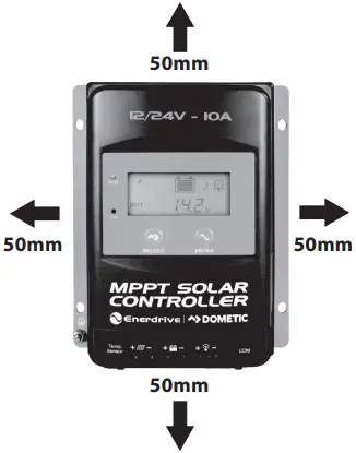
*Figure 2-1: Mounting
![]() CAUTION
CAUTION
If the controller is to be installed in an enclosed box, it is important to ensure reliable heat dissipation through the box.
*Note: Correct ventilation is recommended.
Step 2: Connect the system in the order of 1 battery > 2 load>3 PV array in accordance with Figure 1 Page 6, “Schematic Wiring Diagram” and disconnect the system in the reverse order 3>2>1.
![]() CAUTION
CAUTION
- While wiring the controller do not close the circuit breaker or fuse and make sure that the leads of “+” and “-” poles are connected correctly.
- A fuse which current is 1.25 to 2 times the rated current of the controller, must be installed on the battery side with a distance from the battery or main distribution point not greater than 200 mm.
- If an inverter is to be connected to the system, connect the inverter directly to the battery, not to the load side of the controller.
Step 3: Grounding
Enerdrive MPPT Solar Controllers are a common-negative controller, where all negative terminals of the PV Array, Battery and Loads can be grounded through the controller or at a common ground position where only one negative terminal will need to be present at the unit along with the case ground being connected. However best practice will dictate that all negative terminals should be present at the unit both simplifying the installation and assisting with any fault finding should it be required.
![]() CAUTION
CAUTION
Enerdrive MPPT controllers are not suitable for positively grounded systems.
Step 4: Connect Accessories
- If the batteries being charged are in a different location to the solar controller it is recommended to use the remote temperature sensor.
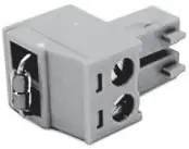
Controller Mounted Temperature Sensor
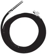
Remote Temperature Sensor
Connect the remote temperature sensor cable to the solar controller and place the other end close to the battery/batteries being charged.
NOTE
If the remote temperature sensor is not connected to the controller, the default setting for battery charging or discharging temperature is 25 °C without temperature compensation.
Step 5: Powering the controller
Closing the battery fuse/circuit breaker will switch on the controller. Then check the status of the battery indicator (the controller is operating normally when the indicator is lit in green). Close the fuse and circuit breaker of the load and PV array. Then the system will be operating in the preprogrammed mode.
 CAUTION
If the controller is not operating properly or the battery indicator on the controller shows an abnormality, please refer to 5.2 “Troubleshooting”.
3. DISPLAY
3.1 OVERVIEW
(1) LED Indicator
INDICATOR | COLOUR | STATUS | INSTRUCTION |
• | Green | On solid | PV connection normal but low voltage (low output) from PV, not charging |
| Green | OFF | No PV voltage (night time) or PV connection problem | |
Green | Slowly Flashing | Charging | |
| Green | Fast Flashing | PV over voltage | |
• | Red | ON SOLID | Load ON |
| Red | OFF | Load OFF |
(2) Buttons
MODE | NOTE |
| Load ON/OFF | When load manual mode is selected, you can turn the load On/Off via the |
Clear Fault | Press the |
| Browsing Mode | Press the |
Setting Mode | Press the |
Press the | |
Press the |
(3) Interface
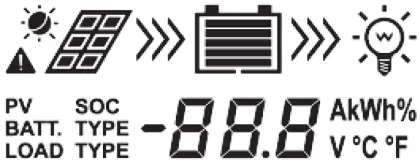
INDICATOR | ICON | STATUS |
PV Array |  | Day |
 | Night | |
No Charging | ||
Charging | ||
PV Voltage, Current, Generated Energy | ||
Battery |  | Estimated Battery Capacity, In Charging |
Battery Voltage, Current, Temperature | ||
Battery Type | ||
Load |  | Load ON |
Load OFF | ||
Current/Consumed Energy/Load mode |
3.2. OPERATION
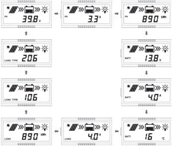
(1) Browse Interface
Press the ![]() button to cycle through the display to show the following interfaces.
button to cycle through the display to show the following interfaces.
 (2) Load Parameter Display
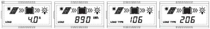
DisplayCurrent/Consumed energy/Load working mode-Timer1/ Load working mode-Timer2
(3) Setting
1 Clear the recorded energy Operation:
Step 1: Press the ![]() button and hold for 5s under the PV recorded energy interface and the value will then be flashing.
button and hold for 5s under the PV recorded energy interface and the value will then be flashing.
Step 2: Press the ![]() button to clear the recorded energy.
button to clear the recorded energy.
2 Switch the battery temperature unit
Press the ![]() button and and hold 5s under the battery temperature interface.
button and and hold 5s under the battery temperature interface.
3 Battery Type
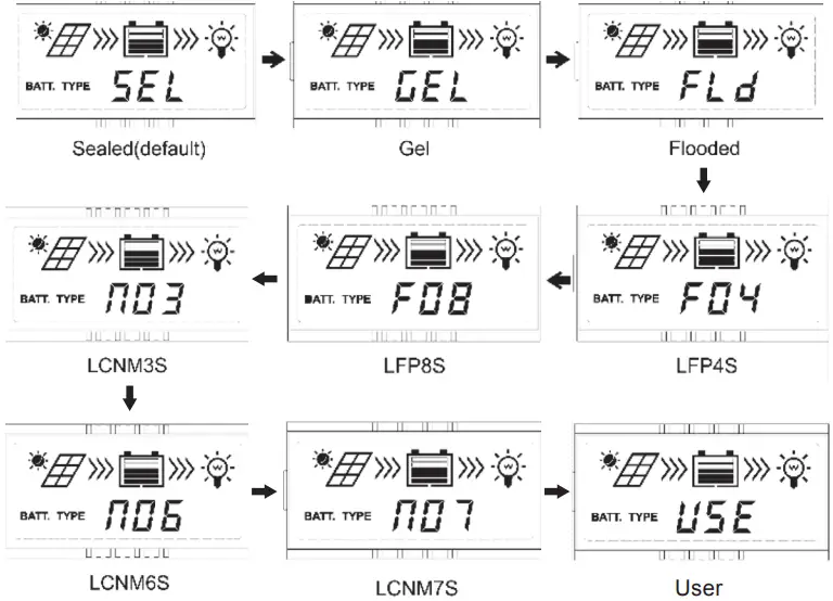
Operation:
Step 1: Press the ![]() button and hold for 5s under the battery voltage interface.
button and hold for 5s under the battery voltage interface.
Step 2: Press the ![]() button when the battery type interface is flashing to cycle through the battery types.
button when the battery type interface is flashing to cycle through the battery types.
Step 2: Press the ![]() button to confirm the battery type.
button to confirm the battery type.
![]() CAUTION
CAUTION
Please refer to chapter 4.1 for the battery parameters setting, when the battery type is “USE”.
4 Load Working Mode

Operation:
Step 1: Press the ![]() button and hold 5s under the load mode interface. ENTER
button and hold 5s under the load mode interface. ENTER
Step 2: Press the ![]() button when the load mode interface is flashing, to cycle through the load settings.
button when the load mode interface is flashing, to cycle through the load settings.
Step 2: Press the ![]() button to confirm the load mode. ENTER
button to confirm the load mode. ENTER
NOTE: Please refer to chapter 4.2 for the load working modes.
4. PARAMETERS SETTING
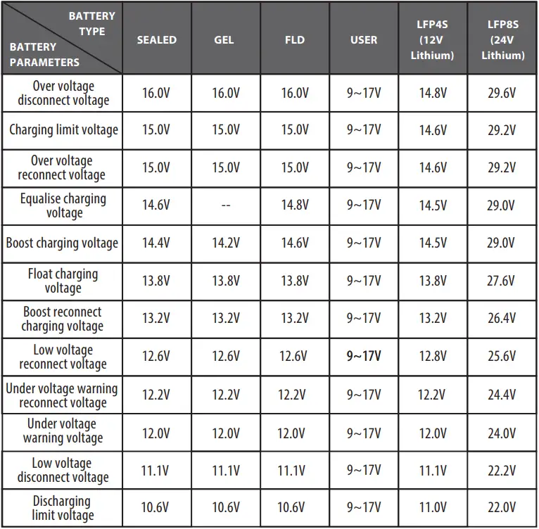
4.1 SUPPORTED BATTERY TYPES
1. | Battery | Sealed (default) |
Gel | ||
Flooded | ||
| 2. | Lithium Battery | LiFePO4(4S/8S) |
Li(NiCoMn) O2 (3S/6S/7S) | ||
| 3. | User | |
NOTE
Enerdrive only recommend to use the Lithium Ion – Li(NiMnCo)O2 battery selection when the controller is installed in specific commercial applications only. (Battery Type NO3, NO6, NO7). For specific charging parameters for this battery type, please contact Enerdrive.
NOTE
When the default battery type is selected, the battery voltage parameters cannot be modified. To change these parameters, select the “USE” type. (Not applicable for Lithium Profiles)
4.1.2 BATTERY TYPE “USE” SETTINGS
Step 1: Enter the “USE” battery type. For detailed operations of entering the “USE” battery type refer to the below instructions.The battery parameters that can be local set are shown in the table below:
| Parameters | Default | Range | Settings on EN43510, EN43520, EN43530 & EN43540 |
| SYS (System Voltage) | 12VDC | 12/24V | 1) Under the “USE” battery type, press the 2) Press the 3) Press the 4) Press the |
| BCU (BULK) | 14.4V | 9~17V | 5) Press the 6) Press the 7) Press the |
| FCU (FLOAT) | 13.8V | 9~17V | |
| LVA (LOW VOLTAGE ALARM) | 12.6V | 9~17V | |
| LVD (LOW VOLTAGE DISCONNECT) | 11.1V | 9~17V | |
| LEN (cut charging below ≤0°C) | NO | YES/NO | Press the Note: Controller will exit automatically from the current interface after no interaction for more than 10 seconds. |
The SYS value can only be modified for battery types other than lithium (F04 for 12V lithium, F08 for 24V Lithium systems). When utilising USE battery type all chemistries other than lithium charging parameters can be modified within the voltage ranges set out in figure 4.1.
Figure 4.1
4.2 LOAD WORKING MODES
1) DISPLAY AND OPERATION
When the LCD shows the above interface, operate as following:
Step 1: Press the ![]() button and hold for 5s to enter the load mode interface.
button and hold for 5s to enter the load mode interface.
Step 2: Press the ![]() button when the load mode interface is flashing.
button when the load mode interface is flashing.
Step 3: Press the ![]() button to confirm the load working modes.
button to confirm the load working modes.
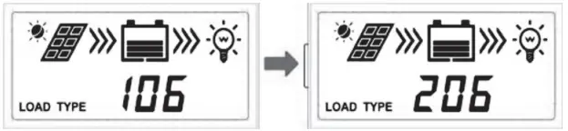
2) LOAD WORKING MODE
1** | Timer 1 – After Sunset | 2** | Timer 2 – Before Sunrise |
| 100 | Light ON/OFF. Must be 101-115 to use 2N function. | 2n | Disabled |
101 | Load will be on for 1 hour after sunset | 201 | Load will be on for 1 hour before sunrise |
| 102 | Load will be on for 2 hours after sunset | 202 | Load will be on for 2 hours before sunrise |
103 ~113 | Load will be on for 3 ~ 13 hours after sunset | 203 ~213 | Load will be on for 3 ~ 13 hours before sunrise |
| 114 | Load will be on for 14 hours after sunset | 214 | Load will be on for 14 hours before sunrise |
115 | Load will be on for 15 hours after sunset | 215 | Load will be on for 15 hours before sunrise |
| 116 | Test mode | 2 n | Disabled |
117 | Manual mode (default load ON) | 2 n | Disabled |
TECHNICAL INFORMATION
Please set Light ON/OFF, Test mode and Manual mode via Timer1. Timer2 will be disabled and display “2 n”.
5. OTHERS
5.1 PROTECTION
PV Over Current/Power | Should the PV array exceed the controllers rated output the controller will go into overdrive maximising the output of the unit, the controller will not exceed its maximum rated output. Exceeding the controllers maximum current input will not damage the unit. If this input exceeds 1.5 times the maximum, it is recommended to install a second controller to maximise input and minimise losses.
|
PV Short Circuit | Short circuiting the PV array connected to the controller will damage the controller. Always ensure to isolate your solar array prior to any work being carried out on either the controller or solar array itself.
|
PV Reverse Polarity |  WARNING: Always ensure PV array polarity prior to connection to the controller. Incorrect polarity will cause damage to the controller. WARNING: Always ensure PV array polarity prior to connection to the controller. Incorrect polarity will cause damage to the controller. |
Night Reverse Charging | Prevents the battery from discharging to the PV module at night. |
Battery Reverse Polarity | Always ensure polarity of battery connections prior to connection. Incorrect polarity will cause damage to the controller.
|
Battery Over Voltage | When the battery voltage reaches the over voltage disconnect voltage, it will automatically stop battery charging to prevent battery damage caused by over-charging. |
Battery Over Discharge | When the battery voltage reaches the low voltage disconnect voltage, it will automatically stop the load circuit to prevent battery damage caused by over-discharging. (Any controller connected loads will be disconnected. Loads directly connected to the battery will not be affected and may continue to discharge the battery.) |
Battery Overheating | The controller can detect the battery temperature through an optional external temperature sensor. The controller stops working when the sensor temperature exceeds 65 °C and restarts when its temperature is below 55 °C. |
Lithium Battery Low Temperature | When the temperature detected by the optional temperature sensor is lower than the Low Temperature Protection Threshold (LTPT), the controller will stop charging automatically. When the detected temperature is higher than the LTPT, the controller will return to normal operation. (The LTPT is 0 °C by default). |
Load Short Circuit | When the controllers load is short circuited the controller will automatically cut o# the output load circuit. The load will then attempt to reconnect after a short delay of 5 seconds. If the short circuit is still present the controller will repeat this process a further 4 times. After the 5th attempt to reconnect, the controller will stay disconnected until the load is manually turned back on through the use of the menu functions on the controller. Please ensure the short circuit has been removed before attempting to turn the load of the controller back on. |
Load Overload | When the load circuit is overloaded the controller will automatically cut o# the output load circuit. The load will then attempt to reconnect after a short delay of 5 seconds. If the overload is still present the controller will repeat this process a further 4 times. After the 5th attempt to reconnect the controller, will stay disconnected until the load is manually turned back on through the use of the menu functions on the controller. Please turn o# some appliances connected to the load circuit to reduce the overall load on this circuit before turning the load back on. |
Controller Overheating* | Enerdrive (EN43510, EN43520, EN43530, EN43540) solar controllers have internal temperature sensors to avoid overheating. The controller will automatically shut down should the internal temperature exceed 85 °C. The controller will return to normal operation when the temperature drops below 75 °C. |
TVS High Voltage Transients | The internal circuitry of the controller is designed with Transient Voltage Suppressors (TVS) which can only protect against high-voltage surge pulses with less energy. |
5.2 TROUBLESHOOTING
| Possible Reasons | Fault Indication | Troubleshooting |
| PV Array Disconnnected | Charging LED indicator o# during daytime when sunshine falls on PV modules properly | Con!rm that PV wire connections are correct and tight |
| Battery Voltage is lower than 8V | Wire connection is correct, the controller is not working. | Please check the voltage of battery. At least 8V required to activate the controller. |
| Battery over Voltage |  Battery level shows full, battery frame and fault icon blink. Battery level shows full, battery frame and fault icon blink. | Check if battery voltage is higher than the OVD (over voltage disconnect voltage) and disconnect the PV. |
CAUTION
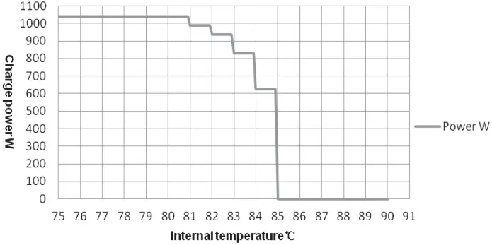
When the internal temperature of the controller is higher than 85 °C, the controller will experience a 5% drop-off in performance for every degree above 80 °C. For example, 84 °C would see the controller lose 20% of its maximum output. If the controller reaches 85 °C, it will stop operation until the temperature drops to below 75 °C. See Figure 4.2.
Figure 4.2
Reduce charging power mode
Battery over Discharged |  Battery level shows empty, battery frame and fault icon blink Battery level shows empty, battery frame and fault icon blink | When the battery voltage is restored to or above the LVR (low voltage reconnect voltage), the load will recover. |
Battery Overheating |  Battery frame and fault icon blink Battery frame and fault icon blink | The controller will automatically turn the system o#. When the temperature declines to below 55 ºC, the controller will resume. |
Controller Overheating | PV/BATT indicator fast $ashing -See Figure 4.2 reduce charging mode | When the heatsync of controller exceeds 85˚C, the controller will automatically cut o# input and output circuit. When the temperature below 75˚C, the controller will resume operation. |
System Voltage Error | ① Check whether the battery voltage matches with the controller working voltage. ② Please change to a suitable battery or reset the working voltage. | |
Load Overload | Reduce load connected to the controller | ① Please reduce the number of loads connected to the load circuits of the controller. ② Restart the controller. |
Load Short Circuit |  Load and fault icon blink Load and fault icon blink | ① Check carefully loads connection, clear the fault. ② Restart the controller. ③ Carefully check load connections before continuing operation. |
5.3 MAINTENANCE
The following maintenance checks are recommended to be carried out at least every 6 months for optimal performance.
- Make sure the controller is securely mounted in a clean dry environment.
- Ensure the unit has good ventilation present on all sides.
- Check all terminals are tight, no broken cables or burnt wire connections from poor connections and inspect cables for any corrosion present and clean accordingly. ·
- Check the unit is functioning correctly with the correct LED indicators. Keep any eye out for any error codes requiring further trouble shooting.
- Confirm that all the system components are grounded correctly.
- Confirm that all the terminals have no corrosion, insulation damage, ensure cables are not burnt or discoloured, and tighten terminal screws.
![]() WARNING
WARNING
Risk of electric shock!
Make sure that all the power is turned off before above operations, and then follow the corresponding inspections and operations.
6. TECHNICAL SPECIFICATIONS
| Enerdrive Part No. | EN43510 | EN43520 | EN43530 | EN43540 |
| Nominal Voltage Range | 12/24VDC Auto¹ | |||
| Battery Voltage Range | 8 ~ 32V | |||
| Maximum Battery Current | 10A | 20A | 30A | 40A |
| Load Current Rating | 10A | 20A | 30A | 40A |
| Maximum PV open circuit voltage | 100V ² | |||
| MPPT Voltage Range | (Battery Voltage +2V) ~ 72V | |||
| Maximum PV Array Power Recommended | 150W/12V 300W/24V | 300W/12V 600W/24V | 450W/12V 900W/24V | 600W/12V 1200W/24V |
| Maximum PV Array Power Allowed (Overdrive) | 180W/12V 360W/24V | 360W/12V 720W/24V | 540W/12V 1080W/24V | 720W/12V 1440W/24V |
| Efficiency (Maximum) | 98.20% | 98.30% | 98.60% | 98.60% |
| Self-Consumption | ≤30mA (12V) | |||
| Temperature Compensate Coefficient 4 | -3mV/°C/12V(Default) | |||
| Grounding | Common negative | |||
| RS485 interface | 5VDC/200mA (RJ45) | |||
| LCD Backlight Timeout | Default: 60S, Range,: 0~999S (OS: the backlight is ON all the time) | |||
| Environmental Parameters | ||||
| Environmental Temperature 5 | -25°C ~ +50°C | |||
| LCD Backlight Timeout | -20°C ~ +70°C | |||
| Relative Humidity | ≤95%, N.C. | |||
| IP Rating | IP33 | |||
| Dimensions (mm) LxWxH | 175x143x48 | 217x158x56.5 | 230x165x63 | 255x185x67.8 |
| Mounting Hole Dimensions (mm) | 120×134 | 160×149 | 173×156 | 200×176 |
| Mounting Hole Size | Ф5mm | |||
| Maximum Cable Size | 12AWG (4mm²) | 10AWG (6mm²) | 8AWG (10mm²) | 6AWG (13.2mm²) |
| Recommended Cable Size | 12AWG (4mm²) | 10AWG (6mm²) | 8AWG (10mm²) | 6AWG (13.2mm²) |
- When lithium battery is used, the system voltage can’t be identified automatically.
- At minimum operating environment temperature.
- At 25°C environment temperature.
- When lithium battery is used, the temperature compensate coefficient must be 0, and can’t be changed.
- The controller can full load working in the environment temperature. When the internal temperature reaches 81°C, the reducing charging power mode is turned on.
CERTIFICATION
Safety | EN/IEC62109-1,UL1741,CSA C22.2#107.1 |
| EMC (Emission immunity) | EN61000-6-3/EN61000-6-1 |
FCC | 47 CFR Part 15, Subpart B |
| Performance & Function | IEC62509 |
ROHS | IEC62321-3-1 |
NOTES
![]()
Dometic Power & Control (Enerdrive) Pty Ltd
P.O. Box 9159, Wynnum Plaza, Queensland, Australia 4178
Ph: 1300 851 535 / Fax: 07 3390 6911
Email: [email protected]
Web: www.enerdrive.com.au


