Jackson AJ/AJX SERIES Electronic Thermostat Retrofit
WARNING! This kit should be installed only by qualified service personnel to reduce the risk of electric shock, serious injury, or fire. A plumbing permit and services of a licensed plumber and electrician might be required in some areas.
CAUTION! Failure to install this kit within the guidelines might adversely affect safety, performance, component life, and warranty coverage.
PREPARATION
- Drain machine completely.
- Ensure incoming water is secured either by use of shut-off valve or by disconnecting incoming water line.
- Disconnect electrical power at breaker or disconnect switch.
- Lock-out/tag-out in accordance with procedures and codes.
TOOLS REQUIRED
Adjustable Wrench, Phillips Screwdriver, Wire Cutter/Stripper
PARTS INCLUDED
| ITEM | QTY | DESCRIPTION | PART NUMBER |
| 1 | 1 | Bracket, Thermostat | 05700-004-21-55 |
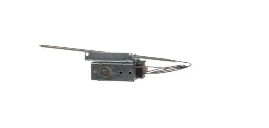
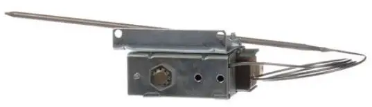
| 2 | 1 | Thermostat, Electronic | 06685-004-17-27 |
| 3 | 2 | Screw, 6-32 x 3/8 | 05305-002-25-91 |
| 4 | 2 | Probe, Thermistor | 06685-004-17-26 |
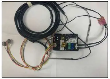
| 5 | 1 | Power Wire Assembly, Thermostat | 05700-005-09-49 |
| 6 | 1 | Probe Wire Assembly, Thermostat | 05700-005-09-50 |
| 7 | 1 | Relay Wire Assembly, Thermostat | 05700-005-09-51 |
| 8 | 2 | Fitting, 1/4 Nut/Sleeve, Brass | 05310-924-02-05 |
PROCEDURE
Phillips screwdriver used in this step.
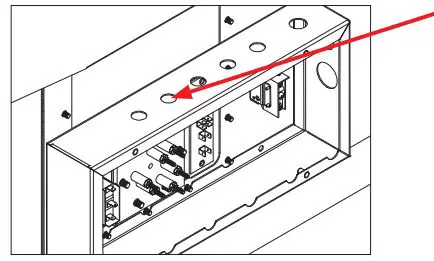
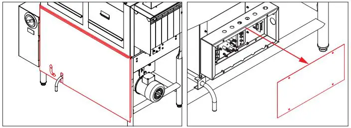
- Remove front dress panel and heater box cover.

New thermostat from kit used in this step. - Remove WHT and BLK wires from new thermostat (will reconnect later).

- Remove stick tape from bottom of thermostat bracket and stick new thermostat to empty space at bottom of heater box.

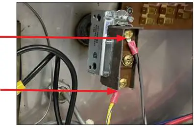
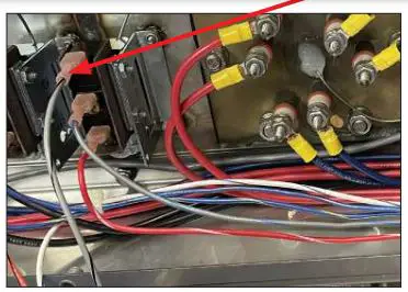
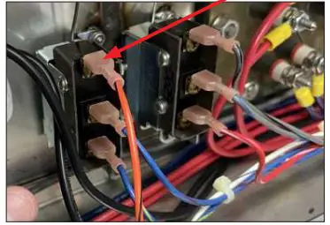
- Remove ORG/BLK and WHT/BLU wires from TS2 and disconnect/discard ORG/ BLK wire.
TS2 = Thermostat 2
Reference machine schematic.
Wire cutter/stripper used in this step.
WHT/BLU wire from kit used in this step. - Cut terminal off WHT/BLU wire and attach to WHT/BLU wire provided in kit.

TS1 = Thermostat 1
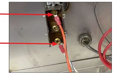
ORG/BLK wire from kit used in this step. - Attach ORG/BLK wire supplied in kit to common on TS1.

TS4 = Thermostat 4
Reference machine schematic. - Remove GRY/BLK and YLW/BLU wires from TS4 and disconnect/discard GRY/ BLK wire.
Wire cutter/stripper used in this step.
YLW/BLU wire from kit used in this step. - Cut terminal off YLW/BLU wire and attach to YLW/BLU wire provided in kit.
TS3 = Thermostat 3
GRY/BLK wire from kit used in this step.
Reference machine schematic. - Attach GRY/BLK wire supplied in kit to common on TS3.
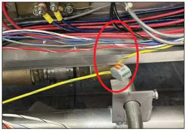
Brass fittings from kit used in this step. - Place brass fittings from kit on temperature probes from kit.
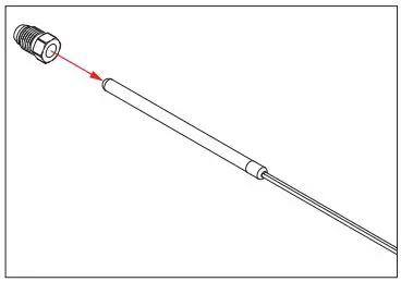
Adjustable wrench used in this step.
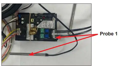
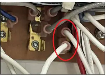
Probes from kit used in this step. - Remove TS2 and TS4 using adjustable wrench and replace with probes from kit. Insert probes 1″ into tub and tighten brass fittings using adjustable wrench (probe 1 is wash, replaces TS2, other probe replaces TS4).
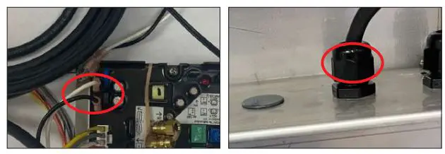
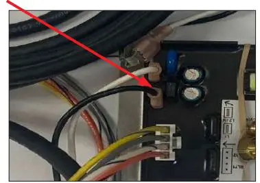
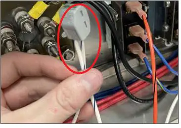
Cord from kit used in this step. - Remove plug from heater box and route wires removed in Step 2 through hole.
Fitting from kit used in this step. - Reconnect WHT and BLK wires removed in Step 2 to same locations on new thermostat. Tighten provided black plastic fitting into heater box.
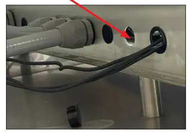
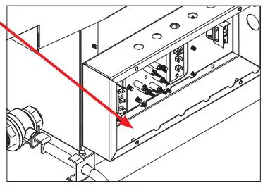
- Remove plug from back of upper control box and route other end of cord with WHT and BLK wires through hole.
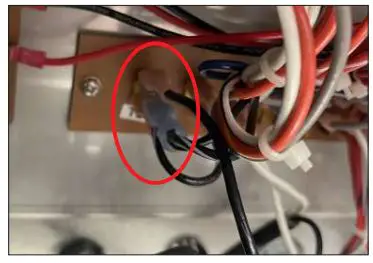
- Attach BLK wire from cord to BLK/WHT on TB2 (use piggyback terminal if necessary).
 Cord from kit used in this step.
Reference machine schematic. - Attach WHT wire from cord to WHT on TB2 (use piggyback terminal if necessary).
- Replace heater box cover and front dress panel.
- Restore power and water to machine.


 Electronic Thermostat User Manual")


