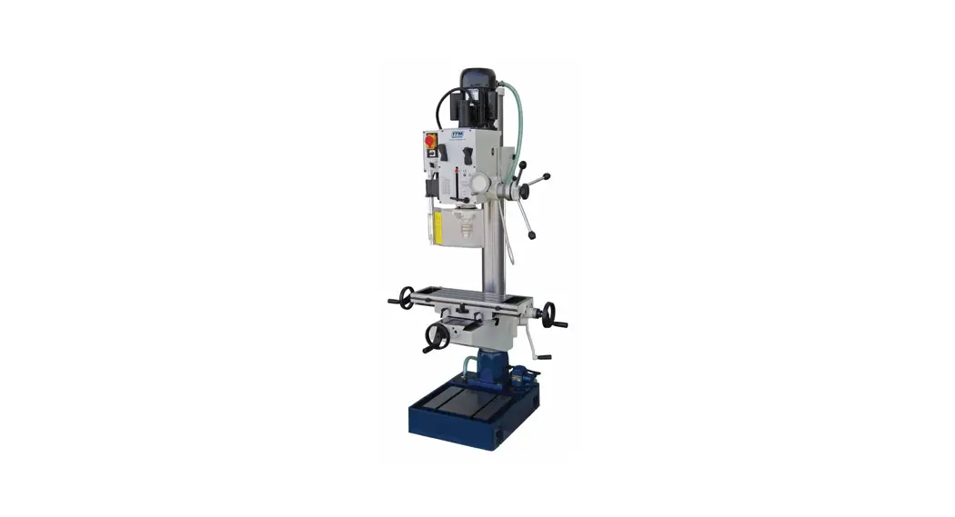
![]() TGMD400 Geared Head Drill-Mill Machine
TGMD400 Geared Head Drill-Mill Machine
Instruction Manual 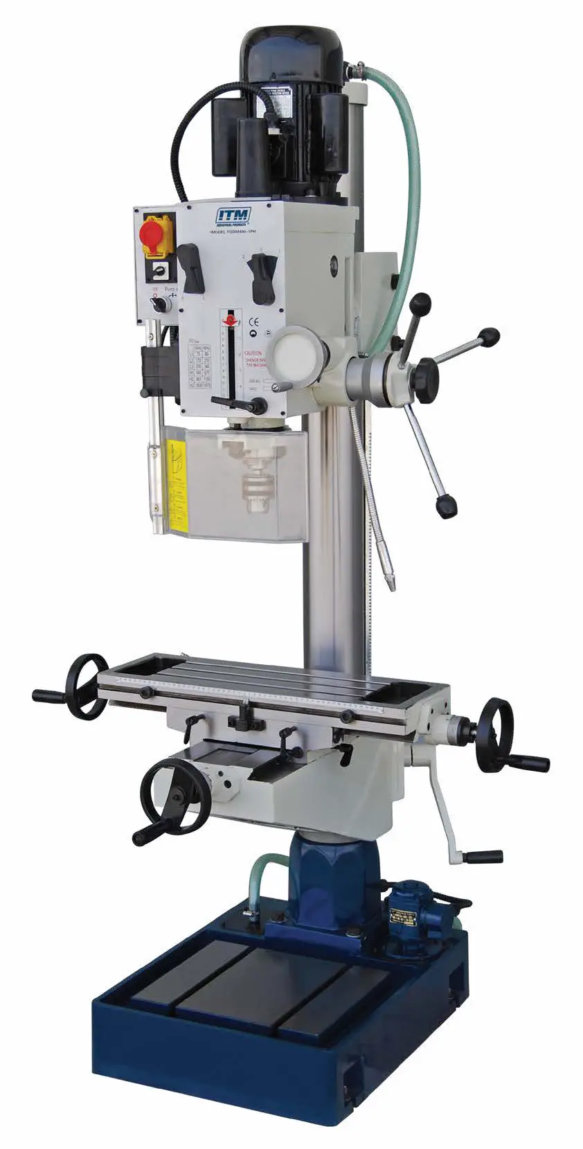 240v 1 Phase Version: Model # TGMD400-1
415v 3 Phase Version: Model # TGMD400-3
BEFORE USE, ENSURE EVERYONE USING THIS MACHINE READS AND UNDERSTANDS ALL SAFETY AND OPERATING INSTRUCTIONS IN THIS MANUAL.
LIMITED WARRANTY
Industrial Tool & Machinery Sales (hereinafter referred to as ITMS) will, within twelve (12) months from the original date of purchase, repair or replace any goods found to be defective in materials or workmanship.
This warranty is void if the item has been damaged by accident, neglect, improper service, or other causes not arising out of defects in materials or workmanship. This warranty does not apply to machines and/or components that have been altered, changed, or modified in any way, or subjected to overloading or use beyond recommended capacities and specifications. Worn componentry due to normal wear and tear is not a warranty claim. Goods returned defective shall be returned prepaid freight to ITMS or agreed on repair agent, which shall be the buyer’s sole and exclusive remedy for defective goods. ITEMS accepts no additional liability pursuant to this guarantee for the costs of traveling or transportation of the product or parts to and from ITMS or the service agent or dealer, such costs are not included in this warranty.
Our goods come with guarantees which cannot be excluded under the Australian Consumer Law. You are entitled to replacement or refund for a major failure and to compensation for other reasonably foreseeable loss or damage. You are also entitled to have the goods repaired or replaced if the goods fail to be of acceptable quality and the failure does not amount to a major failure.
THE MANUFACTURER RESERVES THE RIGHT TO MAKE IMPROVEMENTS AND MODIFICATIONS TO THE DESIGN WITHOUT PRIOR NOTICE.
PRODUCTS IMPORTED AND DISTRIBUTED NATIONALLY BY:![]() INDUSTRIAL TOOL & MACHINERY SALES
INDUSTRIAL TOOL & MACHINERY SALES
18 BUSINESS ST, YATALA QLD 4207
T: 07 3287 1114 E: [email protected]
F: 07 3287 1115 W: www.industrialtool.com.au
SAFETY PRECAUTIONS
Industrial Tool & Machinery Sales (hereinafter referred to as ITMS) will, within twelve (12) months from the original date of purchase, repair or replace any goods found to be defective in materials or workmanship.
Safety – Environment
- Keep work area clean. Cluttered areas and benches invite injury.
- Keep children & unauthorized persons away from the tool. Keep the tool in the work area with authorized trained personnel to use the machine.
- Power tools must be used in dry areas only.
When using power tools outdoors, use a suitable extension cord.
PRIOR TO OPERATION
- Power source; ensure that the power source to be used conforms to the power requirements specified on the nameplate.
- Power switch; ensure that the power switch is in the OFF position before any power is supplied to the machine.
- Extension cord; when an extension cord must be used, ensure it is of sufficient thickness and rated capacity and kept in the shortest length possible while remaining practical.
- Drill protection guard; the machine is provided with a security micro drill Guard.
Before pressing the starting push button, set the drill guard in the working position, otherwise, the machine controls will not start.
Note: If the guard is opened when operating the machine, the machine will stop. Do not remove the guard under any circumstances.
SPECIFICATIONS
| SPECIFICATIONS | TGMD |
| Description | Geared Head Drill / Milling Machine |
| Max Drilling Capacity | 40mm |
| Spindle Taper | 4MT |
| Spindle Nose To Base | 1180mm |
| Spindle Nose To Table | 610mm |
| Spindle To Column | 272.5mm |
| Diameter Of Column | 115mm |
| Quill Travel | 120mm |
| Swing | 660mm |
| Spindle Speeds (rpm) | 75, 170, 280, 540, 960, 1600 |
| Table Surface | 600 x 190mm |
| Cross Travel | 190mm |
| Longitude Travel | 370mm |
| Overall Height | 1770mm |
| Base Dimensions | 650 x 450mm |
| N.W. / G.W. | 340 / 390kg |
| Shipping Dimensions | 820 x 720 x 1830mm |
Safety
Safety -Personal
- Dress properly, and do not wear loose clothing or jewelry, they can invite personal injury. Always cover long hair.
- When operating power tools suitable personal protective equipment must be worn where necessary, including, but not restricted to the eye, ear, respiratory, and foot protection.
- Stay alert, and do not use power tools when tired or under the influence of alcohol, drugs, or medicine as injury may occur.
Safety – Operation
- Secure the work in the vice. Do not hold material by hand.
- Keep proper footing and balance at all times when using the tool.
- Keep hands away from the cutting area while the machine is in operation.
- Guards should be in place and in working order. Remove adjusting keys and wrenches before turning them on.
- Ensure the cutting tool is correctly secured into machine before operation.
Safety – After Use
- Disconnect the machine from power when not in use.
- Store machine in a dry place, well out of reach of children.
MACHINE OPERATION
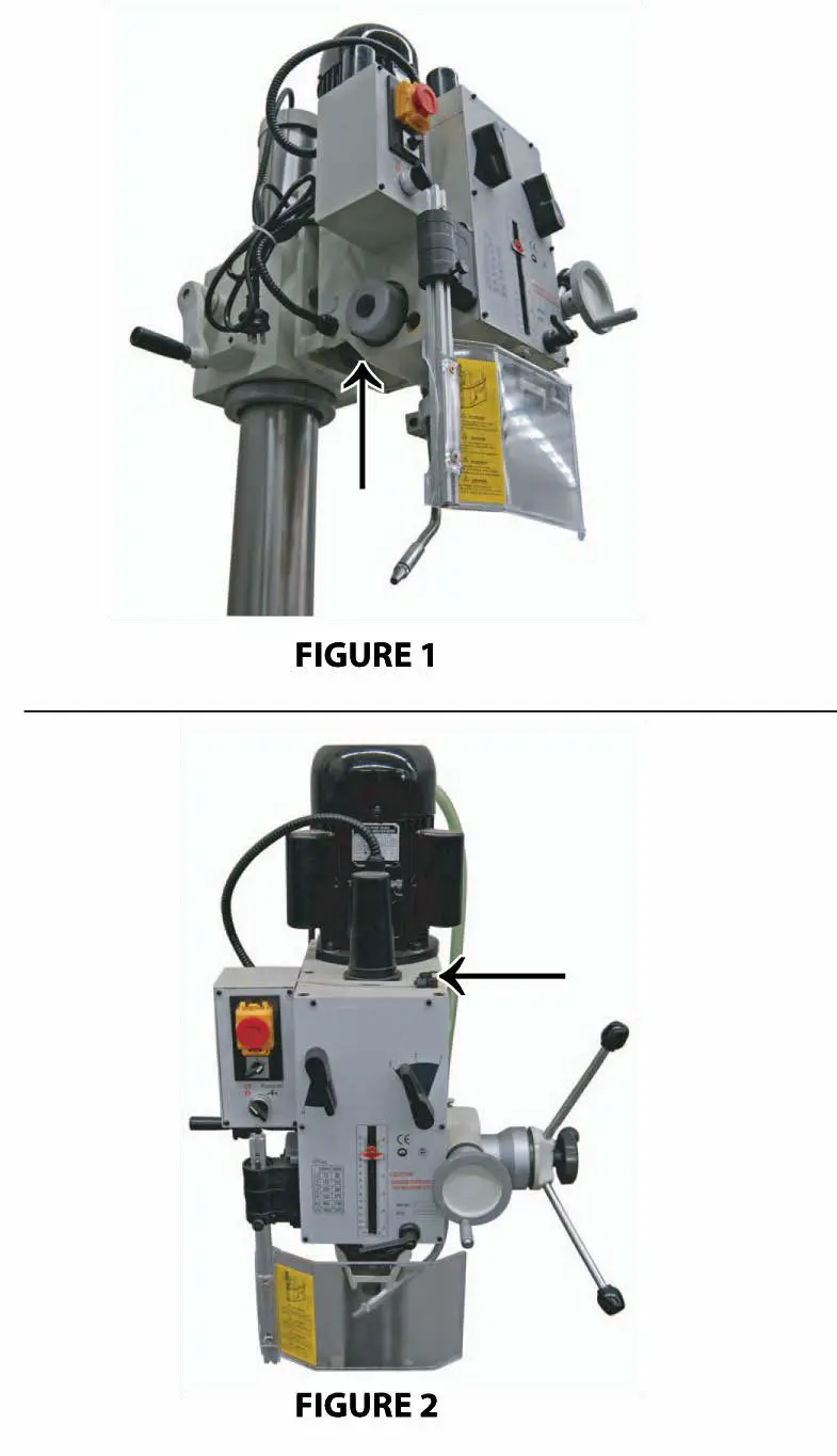
CHANGING THE GEARBOX OIL
Place a bucket to catch the oil onto the work table, then remove the oil drain socket head bolt located within the drill head as shown in Figure 1, and allow the oil to drain from the opening completely. Then replace & tighten the oil drain socket head bolt into its original position. Remove the oil filler bolt shown in figure 2, and fill the oil in the gearbox with standard 80weight gear oil until the oil level reaches the middle of the oil fluid level indicator glass. Then replace and tighten the bolt.
SETUP
- Adjustment of head
(a)To raise and lower the head, loosen the nuts located on the right side of the column bracket.
Turn the crank on the left side of the column bracket until the desired head position is reached.
(b)Head may be rotated 360° by loosening the same nuts mentioned above. Adjust the heat to the desired angle, then tighten the nuts. - Adjustment of the lifting table
(a)Loosen the locking handles positioned on the left side of the table bracket, and turn the crank to move the lifting table up and down along the column. Once the desired height is reached, tighten the handles to prevent the table from falling.
(b)When working with very large items, loosen the locking handles, rotate the work table 180°, then tighten the handles, and place the item being drilled on the base.
CLEANING
- Your machine has been coated with heavy grease to protect it in shipping. This coating should be completely removed before operating the machine. Commercial degreaser, kerosene, or similar solvent may be used to remove the grease from the machine, but avoid getting solvent on belts or other rubber parts.
- After cleaning, coat all bare material with light lubrication. Lubricate all points with a medium consistency machine oil.
LUBRICATION
All ball bearings in your mill/drill are sealed for life, requiring no lubrication. Points requiring lubrication are:
- Internal spline drive assembly. Keep this area well lubricated with a good grade grease, insert grease in the hole at the top of the spindle pulley spline driver, and lube twice yearly.
- A light film of oil applied to the quill and column will reduce wear, prevent rust, and assure ease of operation.
- The Quill return spring should be oiled(see 20) once yearly. Remove the cover plate and apply oil with a squirt can or small brush.
- IMPORTANT: The gearbox should be oiled with a lubricant such as 80W90 oil. CHANGE OIL ONCE A YEAR.
- Apply lubricant to quill pinion every 90 days.
NOTE: use extreme care when performing this 0operation and keep hands clear of pinch points.
When using a paraffin bar, do this only by turning the sheaves in hand. Do not apply with the motor running..
CARE & PRECAUTIONS
- Before Operation
(a)Fill the lubricant
(b)In order to maintain accuracy, the table must be free from dust and oil deposits.
(c)Check to see that the cutting tools are correctly located and the workpiece is clamped firmly. - After Operation
(a)Turn off the electric switches
(b)Clean the machine and coat it with lubricant.
(c)Cover the machine with a cloth to keep out the dust.
MACHINE PARTS – BASE
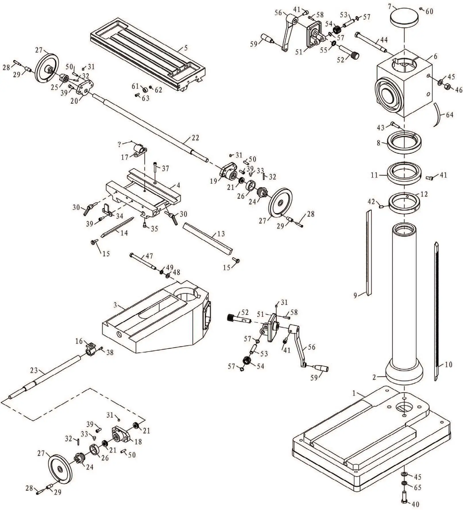
| 1 | QTY | PART # | DESCRIPTION |
| 2 | 1 | 10002/40H | base |
| 3 | 1 | 10001/40H | column |
| 4 | 1 | 10003/40H | lifting table |
| 5 | 1 | 10005/40H | slip saddle |
| 6 | 1 | 10004/40H | work table |
| 7 | 1 | 10016/40H | elevating body |
| 8 | 1 | 10014/40 | column lid |
| 9 | 1 | 10012/40H | locked guide ring |
| ITEM | 1 | 10014/40H | up rack |
| 10 | 1 | 10015/40H | low rack |
| 11 | 1 | 10011/40H | guide ring |
| 12 | 1 | 10013/40H | fixed ring |
| 13 | 1 | 10006/40H | gib strip |
| 14 | 1 | 10007/40H | gib strip |
| 15 | 2 | 10106/40 | adjust screw |
| 16 | 1 | 10203/40 | guide screw nut |
| 17 | 1 | 10202/40 | guide screw |
| 18 | 1 | 10021/40 | guide screw support |
| 19 | 1 | 10020/40 | right support |
| 20 | 1 | 10019/40 | left support |
| 21 | 4 | 10008/40H | bearing 51103 table screw |
| 22 | 1 | ||
| 23 | 1 | 10009/40H | base screw |
| 24 | 2 | 10102/40H | dial clutch |
| 25 | 1 | 10110/40 | left clutch |
| 26 | 2 | 10111/40 | graduation plate |
| 27 | 3 | 10301/40 | handwheel |
| 28 | 3 | 20305-2B/40 | screw |
| 29 | 3 | 20305-1B/40 | turn handle |
| 30 | 3 | adjust handle | |
| 31 | 5 | oil cup 8 | |
| 32 | 3 | pin 5X35 | |
| 33 | 2 | 10107/40 | screw |
| 34 | 1 | 10105/40 | fixed block |
| 35 | 2 | screw M8X16 | |
| 36 | 1 | screw M5X12 | |
| 37 | 1 | screw M8X45 | |
| 38 | 1 | screw M5X16 | |
| 39 | 8 | screw M8X20 | |
| 40 | 4 | bolt M16X50 | |
| 41 | 3 | screw M10X20 | |
| 42 | 3 | screw M10X20 | |
| 43 | 1 | screw M10X40 | |
| 44 | 2 | bolt M16X190 | |
| 45 | 3 | washer 16 | |
| 46 | 2 | nut M16 | |
| 47 | 2 | bolt M12X16 | |
| 48 | 2 | washer 12 | |
| 49 | 2 | washer 12 | |
| 50 | 6 | pin 8X30 | |
| 51 | 2 | 10017/40 | bracket |
| 52 | 2 | 10112/40 | worm shaft |
| 53 | 2 | 10113/40 | small shaft |
| 54 | 2 | helical gear | |
| 55 | 2 | 10201/40 | washer |
| 56 | 2 | 10018/40 | rock handle |
| 57 | 4 | retaining ring | |
| 58 | 8 | screw M6X25 | |
| 59 | 2 | turn handle | |
| 60 | 1 | screw M8X12 | |
| 61 | 2 | 10109/40 | fixed block support |
| 62 | 2 | nut M6 | |
| 63 | 2 | screw M6X16 | |
| 64 | 1 | degree meter | |
| 65 | 1 | washer 16 | |
MACHINE PARTS – HEAD
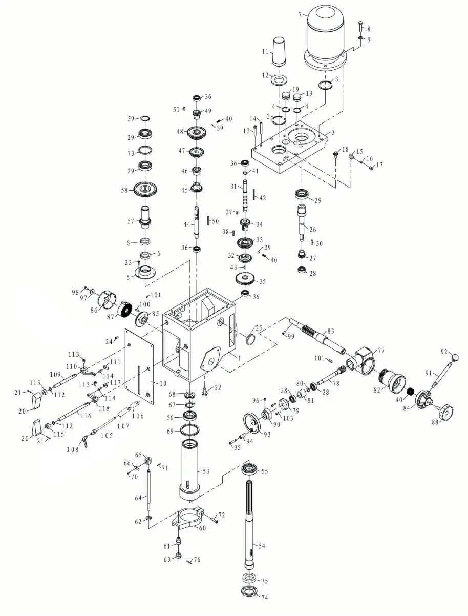
| ITEM | QTY | 20010B | DESCRIPTION |
| 1 | 1 | 20011B | head body cover |
| 2 | 1 | PART # | retaining ring |
| 3 | 2 | retaining ring | |
| 4 | 2 | airtight base | |
| 5 | 1 | 20018B | airtight ring |
| 6 | 2 | motor | |
| 7 | 1 | screw | |
| 8 | 1 | washer | |
| 9 | 1 | plate | |
| 10 | 1 | 20201 | arbor bolt cover |
| 11 | 1 | 20304-1B | arbor bolt cover base |
| 12 | 1 | 20304-2B | screw |
| 13 | 1 | pin | |
| 14 | 1 | joint | |
| 15 | 1 | sleeve | |
| 16 | 1 | nut | |
| 17 | 1 | bolt | |
| 18 | 1 | cap | |
| 19 | 2 | 20020B | DESCRIPTION |
| 20 | 2 | 20307B | speed lever |
| 21 | 2 | pin | |
| 22 | 1 | oil plug | |
| 23 | 1 | screw | |
| 24 | 1 | screw | |
| 25 | 1 | oil pointer | |
| 26 | 1 | 20105B | shaft |
| 27 | 1 | 20105-1-B | gear |
| 28 | 3 | bearing | |
| 29 | 3 | bearing | |
| 30 | 1 | key | |
| 31 | 1 | 20106B | shaft |
| 32 | 1 | 20108-B | gear |
| 33 | 1 | 20110-1-B | gear |
| 34 | 1 | 20111-B | gear |
| 35 | 1 | 20106-1-B | gear |
| 36 | 4 | bearing | |
| 37 | 1 | key | |
| 38 | 1 | key | |
| 39 | 2 | ball | |
| 40 | 1 | spring | |
| 40/1 | 1 | spring | |
| 41 | 2 | retaining ring | |
| 42 | 1 | key | |
| 43 | 4 | screw | |
| 44 | 1 | 20107B | shaft |
| 45 | 1 | 20109-B | gear |
| 46 | 1 | 20110-2-B | gear |
| 47 | 1 | 20112-B | gear |
| 48 | 1 | 20113-B | gear |
| 49 | 1 | gear | |
| 50 | 1 | key | |
| 52 | 1 | key | |
| 53 | 1 | 20019 | spindle sleeve |
| 54 | 1 | 20104B | spindle |
| 55 | 1 | bearing | |
| 56 | 1 | bearing | |
| 57 | 1 | 20114-B | splined sleeve |
| 58 | 1 | 20116-B | gear |
| 59 | 1 | retaining ring | |
| 60 | 1 | 20012 | feed base |
| 61 | 1 | 20128 | support base |
| 62 | 1 | 20129 | nut |
| 63 | 1 | 20130 | knob |
| 64 | 1 | 20131 | graduated rod |
| 65 | 1 | 20021 | fixed bolt |
| 66 | 1 | 20132 | scale board |
| 67 | 1 | lock washer | |
| 68 | 1 | lock nut | |
| 69 | 1 | 20308 | rubber washer |
| 70 | 1 | screw | |
| 71 | 1 | split pin | |
| 72 | 1 | bolt | |
| 73 | 1 | 20024B | separating ring |
| 74 | 1 | 20133B | oil tight cover |
| 75 | 1 | 62*42*12 | air tight |
| 76 | 1 | pin | |
| 77 | 1 | 20015 | worm wheel box |
| 78 | 1 | 20119 | worm shaft |
| 79 | 1 | 20302 | worm cover |
| 80 | 1 | retaining ring | |
| 81 | 1 | 20120 | separating ring |
| 82 | 1 | 20016 | worm wheel |
| 83 | 1 | 20117 | pinion shaft |
| 84 | 1 | 20013 | handle body |
| 85 | 1 | 20118 | spring base |
| 86 | 1 | 20123 | spring cap |
| 87 | 1 | 20122 | spring plate |
| 88 | 1 | 20303 | big ripple handle |
| 90 | 1 | 20017 | graduated plate |
| 91 | 1 | 20121B | handle rod |
| 92 | 1 | 20301B | handle ball |
| 93 | 1 | 20306B | handle wheel |
| 94 | 1 | 20305-1B | turn handle |
| 95 | 1 | 20305-2B | screw |
| 96 | 1 | screw | |
| 97 | 1 | 20102 | washer |
| 98 | 1 | bolt | |
| 99 | 1 | screw | |
| 100 | 1 | screw | |
| 101 | 2 | pin | |
| 102 | 1 | key | |
| 104 | 2 | screw | |
| 105 | 1 | 20124B | fixed bolt |
| 106 | 1 | 20203B | fixed tight block |
| 107 | 1 | 20202B | fixed tight block |
| 108 | 1 | adjust handle | |
| 109 | 1 | 20125B | lever shaft |
| 110 | 1 | 20022-1B | lever |
| 111 | 1 | 20204-2B | lever bracket |
| 112 | 2 | retaining ring | |
| 113 | 2 | screw | |
| 114 | 2 | 20204-3B | lever rod |
| 115 | 2 | oil seal | |
| 116 | 1 | 20126B | long lever shaft |
| 117 | 1 | 20204-1B | lever bracket |
| 118 | 1 | 20022-2B | lever |


