![]()
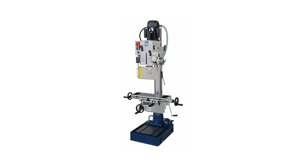
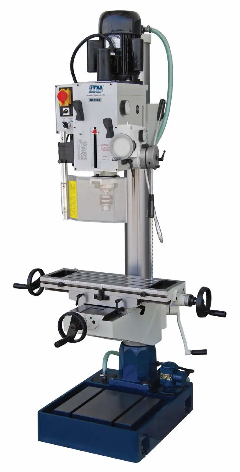
TGMD400A
GEARED HEAD DRILL / MILL MACHINE AUTOMATIC
OPERATOR’S MANUAL
![]() 240v 1 Phase Version: Model # TGMD400A-1
240v 1 Phase Version: Model # TGMD400A-1![]() 415v 3 Phase Version: Model # TGMD400A-3
415v 3 Phase Version: Model # TGMD400A-3
BEFORE USE, ENSURE EVERYONE USING THIS MACHINE READS AND UNDERSTANDS ALL SAFETY AND OPERATING INSTRUCTIONS IN THIS MANUAL.
Serial #…………………………………….. Date of Purchase……………………….
Ver: 1.04 17/03/2022
LIMITED WARRANTY
Industrial Tool & Machinery Sales (hereinafter referred to as ITMS) will, within twelve (12) months from the original date of purchase, repair or replace any goods found to be defective in materials or workmanship. This warranty is void if the item has been damaged by accident, neglect, improper service or other causes not arising out of defects in materials or workmanship. This warranty does not apply to machines and/or components which have been altered, changed, or modified in any way, or subjected to overloading or use beyond recommended capacities and specifications. Worn componentry due to normal wear and tear is not a warranty claim. Goods returned defective shall be returned prepaid freight to ITMS or agreed repair agent, which shall be the buyer’s sole and exclusive remedy for defective goods. ITMS accepts no additional liability pursuant to this guarantee for the costs of travelling or transportation of the product or parts to and from ITMS or the service agent or dealer, such costs are not included in this warranty.
Our goods come with guarantees which cannot be excluded under the Australian Consumer Law. You are entitled to replacement or refund for a major failure and to compensation for other reasonably foreseeable loss or damage. You are also entitled to have the goods repaired or replaced if the goods fail to be of acceptable quality and the failure does not amount to a major failure.
THE MANUFACTURER RESERVES THE RIGHT TO MAKE IMPROVEMENTS AND MODIFICATIONS TO DESIGN WITHOUT PRIOR NOTICE.
![]()
PRODUCTS IMPORTED AND DISTRIBUTED NATIONALLY BY: INDUSTRIAL TOOL & MACHINERY SALES 18 BUSINESS ST, YATALA QLD 4207
T: 07 3287 1114 E: [email protected]
F: 07 3287 1115 W: www.industrialtool.com.au
Safety Precautions
WARNING: FAILURE TO FOLLOW THESE RULES MAY RESULT IN SERIOUS PERSONAL INJURY
As with all machinery there are certain hazards involved with operation and use of the machine. Using the machine with respect and caution will considerably lessen the possibility of personal injury. However, if normal safety precautions are overlooked or ignored, personal injury to the operator
may result.
This machine was designed for certain applications only. We strongly recommends that this machine. NOT be modified and/or used for any application other than for which it was designed. If you have any questions relative to its application DO NOT use the machine until you have had detail instruction from your dealer.
SAFETY RULES FOR ALL TOOLS
- FOR YOUR OWN SAFETY, READ THIS INSTRUCTION MANUAL BEFORE OPERATING THE TOOL. Learn the tool’s application and limitations as well as the specific hazards peculiar to it.
- KEEP GUARDS IN PLACE and in working order .
- GROUND ALL TOOLS.If tool is equipped with three-prong plug, it should be plugged into a three-hole electrical receptacle. If an adapter is
used to accommodate a two-prong plug receptacle, the adapter lug must be attached to a know ground. Never remove the third prong. - REMOVE ADJUSTING AND WRENCHES. Form habit of checking to see that keys and adjusting wrenches are removed from tool before turning it”on.”
- KEEP WORK AREA CLEAN. Cluttered areas and benches invite accidents.
- DON’T USE IN DANGEROUS ENVIRONMENT. Don’t use power tools in damp or wet locations, or expose them to rain. Keep work area well-lighted.
- KEEP CHILDREN AND VISITORS AWAY. All children and visitors should be keep a safe distance from work area.
- MAKE WORKSHOP CHILDPROOF – with padlocks, master switches, or by removing starter keys.
- Don’t force tool. It will do the job better and be safer at the rate for which it was designed.
- USE RIGHT TOOL .Don’t force tool or attachment to do a job for which it was not designed.
- WEAR PROPER APPAREL. No loose clothing,gloves,neckties,rings, bracelets, or other jewelry to get caught in moving parts. Nonslip foot wear is recommended. Wear protective hair covering to contain long hair.
- ALWAYS WEAR EYE PROTECTION. Refer to ANSIZ87.1 Standard for appropriate recommendations. Also use face or dust mask if cutting
operation is dusty. - SECURE WORK. Use clamps or a vise to hold work when practical. It’s safer than using your hand and frees both hands to operate tool.
- DON’T OVERREACH. Keep proper footing and balance at all times.
- MAINTAIN TOOLS IN TOP CONDITION. Keep tools sharp and clean for best and safest performance. Follow instructions for lubricating and changing accessories.
- DISCONNECT TOOLS before servicing and when changing accessories such as blades, bits, cutters,etc.
- USE RECOMMENDED ACCESSORIES. Consult the owner’s manual for recommended accessories. The use of improper accessories may cause hazards.
- AVOID ACCIDENTAL STARTING. Make sure switch is in “OFF” position before plugging in power cord.
- NEVER STAND ON TOOL. Serious injury could occur if the tool is tipped or if the cutting tool is accidentally contacted
- CHECK DAMAGED PARTS. Before further use of the tool, a guard or other part that is damaged should be carefully checked to ensure that it will operate properly and perform its intended function check for alignment of moving parts binding of moving parts, breakage of parts mounting, and any other conditions that may affect its operation. A guard or other part that is damaged should be properly repaired or replaced.
- DIRECTION OF FEED. Feed work into a blade or cutter against the direction of rotation of the blade or cutter only.
- NEVER LEAVE TOOL RUNNING UNATTENDED.TURN POWER OFF. Don’t leave tool until it comes to a complete stop.
- DRUGS, ALCOHOL, MEDICATION. Do not operate tool while under the influence of drug, alcohol or any medication.
- MAKE SURE TOOL IS DISCONNECTED FROM POWER SUPPLY while motor is being mounted, connected or reconnected.
ADDITIONAL SAFETY RULES FOR MILL DRILL
- BE SURE drill bit or cutting tool is securely locked in the chuck.
- BE SURE chuck key is removed from the chuck before turning on power.
- Adjust the table or depth stop to avoid drilling into the table.
- SHUT OFF the power,remove the drill bit or cutting tool, and clean the table before leaving the machine.
- CAUTION. When practical, use clamps or a vise to secure workpiece to keep the workpiece from rotating while the drill bit or cutting tool.
- WARNING: FOR Your Own Safety Don’t wear gloves when operating a mill/drill.
SPECIFICATION
| Part No. | TGMD400A-1 TGMD400A-3 |
| Description | Bench Mill / Drill |
| Max Drilling Capacity | 40mm |
| Spindle Taper | #4 Morse Taper |
| Spindle Nose To Base | 1180mm |
| Spindle Nose To Table | 610mm |
| Spindle To Column | 272.5mm |
| Diameter Of Column | 115mm |
| Quill Travel | 120mm |
| Swing | 660mm |
| T-Slot | 12mm |
| Spindle Speeds | 75, 170, 280, 540, 960, 1600rpm |
| Table Dimensions | 600 x 190mm |
| Cross Travel | 190mm |
| Longitude Travel | 370mm |
| Overall Height | 1770mm |
| Base Dimensions | 650 x 450mm |
| N.W. / G.W. | 340 / 390kg |
| Shipping Dimensions | 820 x 720 x 1830mm |
WARNING: CHANGE SPEED ONLY WHEN MACHINE IS STOPPED
Maintenance
CHANGING THE GEAR BOX OIL
Tilt the head stock over as shown in Fig 1.Open the drain plug to allow the oil to drain from the opening completely. Then lock the oil drain plug and turn the head to be upright position. Remove the oil filler plug fill the oil to the gear box until the oil lever reach the middle of oil fluid lever indicator.
Then lock the plug.
CLEANING
- Your machine has been coated with a heavy grease to protect it in shipping. This coating should be completely removed before operating the machine. Commercial degreaser, kerosene or similar solvent may be used to remove the grease from the machine, but avoid getting solvent on belts or other rubber parts.
- After cleaning, coat all bright work with a light lubrication. Lubricate all points with a medium consistency machine oil.
LUBRICATION:
All ball bearings in your mill/drill are sealed for life, requiring no lubrication. Points requiring lubrication are:
- Internal spline drive assembly. Keep this area well lubricated with a good grade grease , insert grease in the hole at the top of spindle pulley spline
driver, lube twice yearly. - A light film of oil applied to the quill and column will reduce wear, prevent rust, and assure ease of operation.
- Quill return spring should receive oil once yearly. Remove cover plate and apply oil with squirt can or small brush.
- IMPORTANT: The gear box should be oiled with a lubricant such as sae 68 oil in level. CHANGE OIL EVERY ONE YEAR.
- Apply lubricant to quill pinion every 90 days.
NOTE: use extreme care when performing this operation and keep hands clear of pinch points. When using paraffin bar, do this only by
turning the sheaves by hand. Do not apply with motor running.
USE OF MAIN MACHINE PARTS
- To raise and lower the head by head handle.
- Equipped with an electric switch for tapping operation clockwise or counterclock wise.
- To adjust the quick or slow feeding by feed handle.
- To adjust the table left and right travel by table handle wheel.
- To adjust the table fore and after travel by table handle wheel.
- To operate the spindle handle wheel for micro feed.
- To adjust the scale size according to working need.
PRECAUTION FOR OPERATION
Check all parts for proper condition before operation; if normal safety precautions are noticed carefully, this machine can provide you withstanding of accurate service.
Drill protection guard; the machine is provided with a security micro drill guard. Before pressing the starting push button, set the drill guard in the working position, otherwise the machine controls will not start.
Note: If the guard is opened when operating the machine, the machine will stop. Do not remove the guard under any circumstances.
- Before Operation
(a) Fill the lubricant
(b) In order to keep the accurate precision, the table must be free from dust and oil deposits.
(c) Check to see that the tools are correctly set and the workpiece is set firmly.
(d) Be sure the speed is not set too fast.
(e) Be sure everything is ready before use - After Operation
(a) Turn off the electric switch.
(b) Turn down the tools.
(c) Clean the machine and coat it with lubricant.
(d) Cover the machine with cloth to keep out the dust. - Adjustment of head
(a) To raise and lower the head, loosen the leaf screw located on the right side of the raise and lower base. When the desired height is reached tighten leaf screw to avoid vibration.
(b) Head may be rotated 360 °by loosening the same bolts mentioned above. Adjust the head to the desired angle, then fix the heavy duty head locknuts, It is tighten the same to fix the head if drilling &milling too much.
(c) Unscrew 3 nuts while the workpiece needs to be drilled. Turn to the degrees you wish on the scale, then screw the 3 nuts. - Adjustment of the lifting table
(a) Loosening the locking handles, rocking the crank to move the lifting table up and down along the column, when arrived the height of your request, tighten the handles to prevent loose.
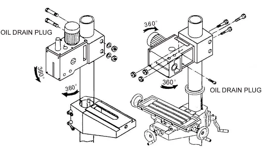 Fig.1
Fig.1
(b) When need to working large parts, loosening the locking handles, rotating the lifting table of 180 °, then tighten the handles, and place the part on the base to work on it.
QUILL RETURN SPRING ADJUSTMENT:
Spring tension for return of spindle, after hole drilling, has been pre-set at the factory. No further adjustment should be attempted unless absolutely
necessary. Adjustment will probably be required if a multiple spindle drilling or tapping head is used. If adjustment is necessary, loosen lock screw while
holding quill spring housing. Do not allow the housing to turn in your hand,or spring will unwind. Turn entire housing assembly clockwise the number of turns necessary to cause the quill to return to its up position.(NOTE: The flat of the spring housing pilot is lined up with the spring loading hole on the body of the spring housing.) Reset lockscrew make sure point of screw mates the flat on the housing journal.
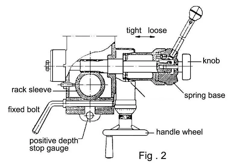
- Preparing for Drilling(see fig.2)(Except addition power feed system).
Turn of the knob make loose the taper body of worm gear and spring base. Then we decide spindle stroke setting the positive depth stop gauge for drilling blind hole or free state for pass hole.
- Preparing for milling(see fig.2)( Except addition power feed system)
(a)Adjust the positive depth stop gauge to highest point position.
(b)Turn tight of the knob be use to taper friction force coupling the worm gear and spring base. Then turning the handle wheel by micro set the
spindle of work piece machining height.
ADJUSTING TABLE SLACK AND COMPENSATE FOR WEAR(see fig.3)
- Your machine is equipped with jib strip adjustment to compensate for wear and excess slack on cross and longitudinal travel.
- Clockwise rotation the job strip bolt with a big screw for excess slack otherwise a little counter clockwise if too tight.
- Adjust the jib strip bolt until feel a slight drag when shifting the table.
CLAMPING TABLE BASE AND MACHINE BASE(See Fig.3)
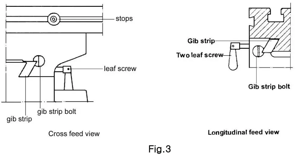
- When milling longitudinal feed. It is advisable to lock the cross feed table travel to insure the accuracy of your work. To do this, tighten the small leaf screw located on the right side of the table base.
- To tighten the longitudinal feed travel of the table for cross feed milling, tighten the two small leaf screw on the front of the table base.
- Adjustable travel stops are provided on the front of the table for control of cross travel and the desired milling length.
TO CHANGE TOOLS
- Removing Face Mill or Drill Chuck Arbor Loosen the arbor bolt at the top of the spindle shaft approximately 2 turns with a wrench. Rpa the top of the arbor bolt with a mallet. After taper has been broken loose, holding chuck arbor on hand and turn detach the arbor bolt with the other hand.
- To install Face Mill or Cutter Arbor Insert cutter and cutter arbor bolt detach securely, but do not over-tighten.
- Removing Taper Drills
(a) Turn down the arbor bolt and insert the taper drill into the spindle shaft.
(b) Turn the rapid down handle rod down until the oblong hole in the rack sleeve appears. Line up this hole with the hole in the spindle. Insert
key punch key through holes and strike lightly with a mallet. This will force the taper drill out.
SPECIFICATION OF T—SLOT
The size of T-Solt on table as Fig.4.
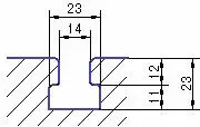
Fig.4
TROUBLESHOOTING HINTS
| TROUBLE | PROBABLE CAUSE | REMEDY |
| Excessive Vibration | 1. Motor out of balance 2. Bad motor | 1. Balance or replace problem motor. 2. Replace motor |
| Motor stalls | 1.over feeding. 2. Dull dd. 3. Motor not building up to running speed 4. Bad motor | 1. Reduce feed rate. 2. Sharpen drill and keep sharp. 3. Replace or repair motor. Check fuses in all three legs on three-phase motors and replace if necessary. 4. Replace motor. |
| Noisy Operation | 1. Excessive vibration. 2. Improper quill adjustment. 3.Noisy spline 4. Noisy motor | 1. Check remedy under excessive vibration. 2. Adjust quill. 3. Lubricate spline. 4. Check motor bearings or for loose motor fan. |
| Drill or Tool heats up or burns work. | 1. Excessive speed. 2. Chips not clearing. 3.0ull tool. 4. Feed reate too slow. 5. Rotation of drill incorrect. 6. Failure to use cutting al or coolantlon steel) | 1. Reduce speed. 2. Use pecking operation to clear chips. 3. Sharpen tool or replace. 4. Increase feed enough to clear chips. 5. Reverse motor rotation. 6. Use cutting oil or coolant on steel |
| Drill leads off | 1.No drill spot. 2. Cutting lips on drill off-center. 3. Ouill loose in head. 4.Bearing play. | 1. Center punch or center drill workpiece. 2. Regrind drill. 3. Tighten quill. 4. Check bearings and reseat or replace if necessary. |
| Excessive drill runout or wobble | 1. Bent chill. 2. Bearing play. 3. Drill not seated properly in chucks. | 1. Replace drill. Do not attempt to straighten 2. Replace or reseat bearings. 3.Loosen.reseat and tighten chuck. |
| Work or fixture comes loose or spins | 1. Failure to clamp workpiece or work holding device to table. | 1. Clamp workpiece or work holding device to table surface. |
Power feed device
This machine is equipped with the power feed device
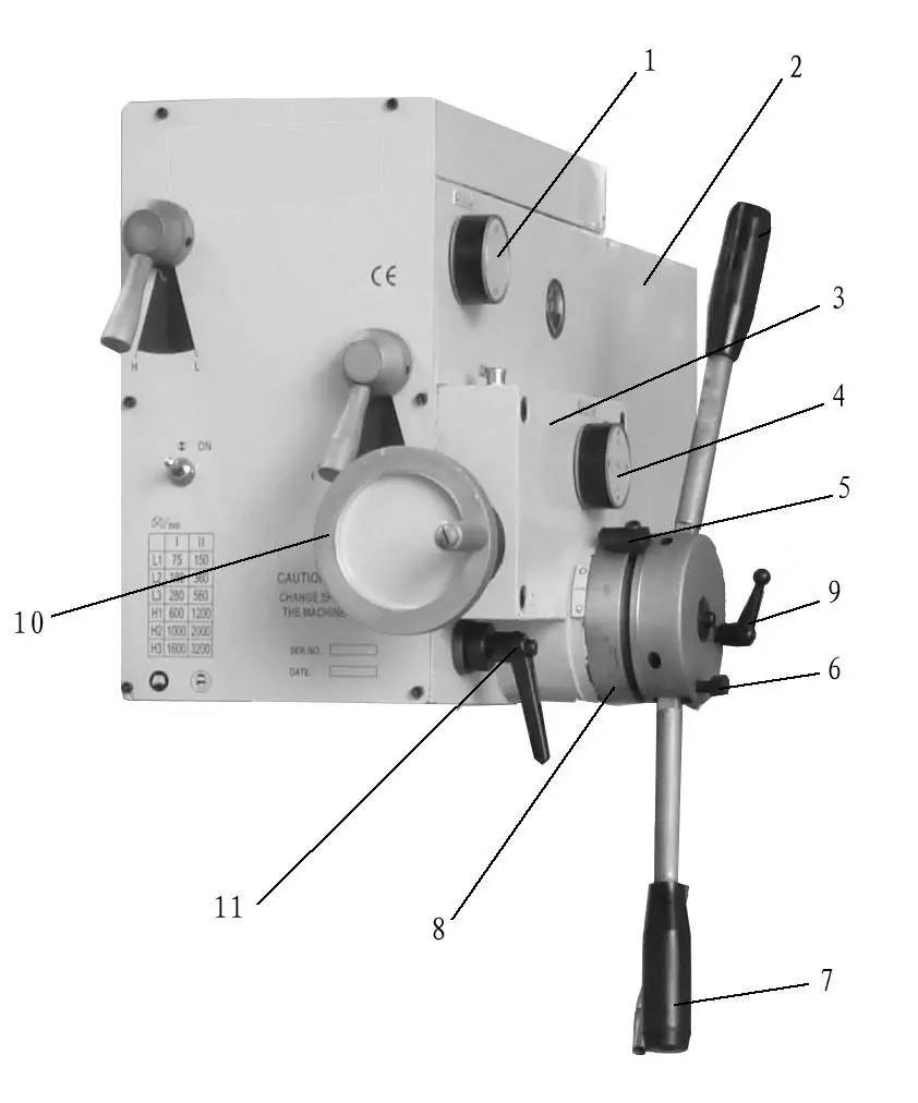
| 1. Power feed switch 2. Main transmission box 3. Feed box 4. Feed amount operation knob 5. Travel dog | 6. Limited handle 7. Feed operation handle 8. Spindle stroke dial 9. Dial locked handle 10. Manual feed handle 11. Locking handle of spindle sleeve |
Operation procedure
- Drilling
a. When drilling, reaming, boring and enlarging the holes, pull Feed operation handle7, the spindle can be moving down rapidly. When perform auto feed, draw Feed operation handle 7 to the right. The auto spindle feed was designed for this machine, there are three feed capacity for selection. Move spindle to the designed position. First loose Dial locked handle 9, then adjust the Spindle stroke dial 8 to designed depth ,tighten the Dial locked handle 9,start the machine can power feed ,when spindle arrived at the designed depth , automatically the Feed operation handle7 turn back, and the spindle sent back.
b. Draw the Feed operation handle 7 to the left to stop auto feed ,and locked the Limited handle 6 to prevent the Feed operation handle to right ,then the machine can be manually feed spindle.
c. When perform tapping ,turn Feed switch knob 1 and Feed amount operation knob 4 to “OFF” position and tighten Limited handle 6, then loose Dial locked handle 9,adjust Spindle stroke dial 8 to designed depth, tighten Dial locked handle 9, operating Feed operation handle 7 to make Spindle stroke dial ”0”position to “l” position .Adjust Travel dog 5 to the pulley of Travel switch ,force the Travel switch on pressed state, and make Feed operation handle 7 turn back to original position, then start the machine to tap ,when the tap to the designed depth ,the Travel dog 5 bump on the Travel switch ,the spindle rotating negatively ,when the spindle back to the original position, the spindle rotating positively, then prepare to tap the next hole. - Milling
a. When processing milling, turn the feed switch knob 1 and feed capacity knob 4 to the OFF position, tightly turn the limit handle 6. When setting the tools, adjust the dial located at the manual feed hand wheel to “0”, adjust the hand wheel 10 to the requested processing depth.
b. Tightly turning the locking handle 11 of spindle sleeve when milling to ensure the milling accuracy and roughness.
c. Having finished milling, loose the locking handle 11 first, turn the manual feed hand wheel 10 reversely to make it return to the original; You may also loose the limit handle 6, draw the control handle 7 to the left, make it return to the original by the worm spring.
d. When processing cross milling, turn the 2 PCS screws on the right side of cross slide, lock the longitudinal movement to ensure the processing accuracy. As Dia.3
e. When processing longitudinal milling, turn the 2PCS screws on the front side of cross slide to lock the cross movement. As Dia.3.
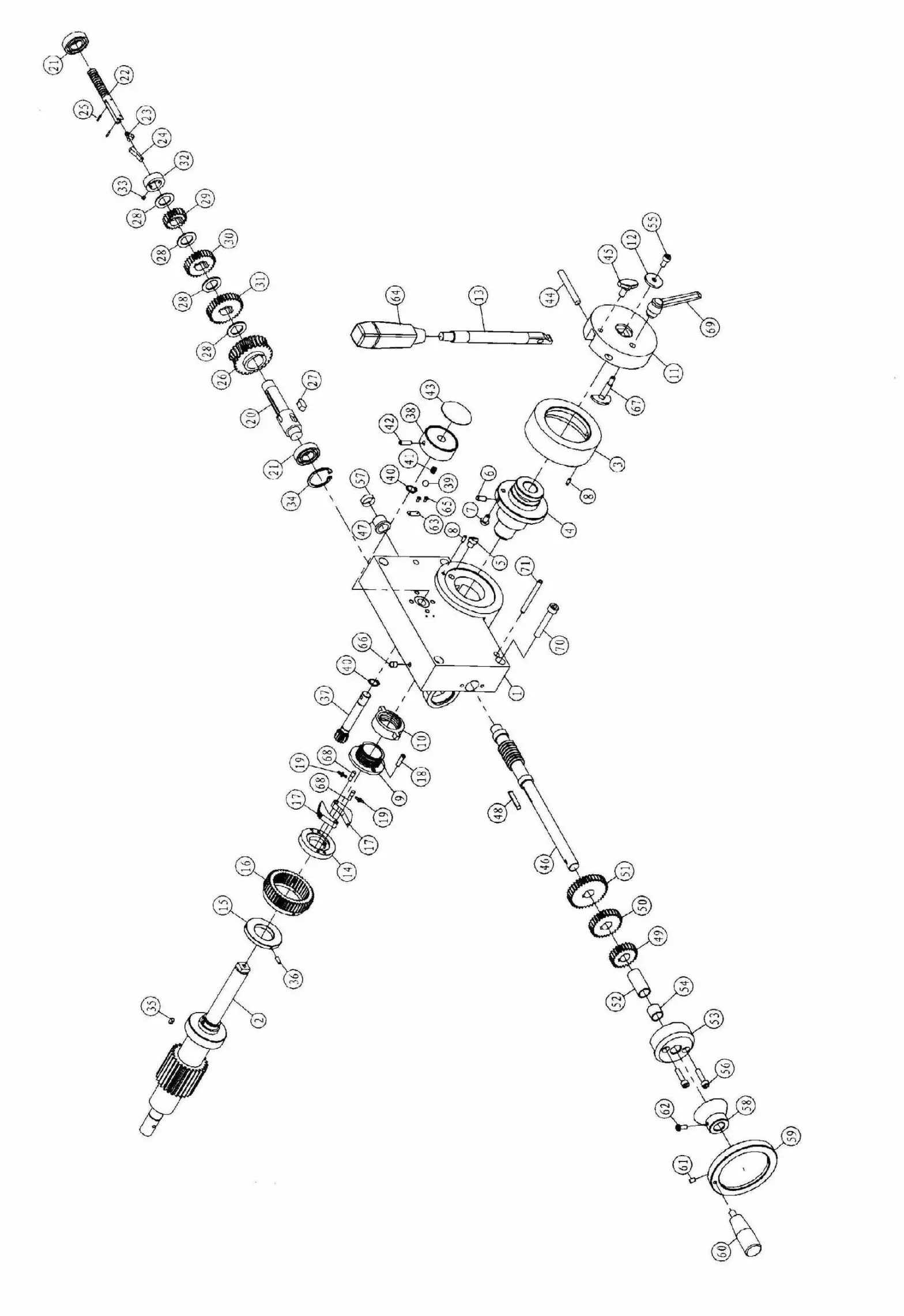
FEED BOX
FEED BOX PARTS
| No | Code | Qty. | Name | No | Code | Qty | Name | |
| 1 | 20102 | 1 | Feed box | 37 | 20202 | 1 | Gear | |
| 2 | 20234 | 1 | Pinion shaft | 38 | 20201 | 1 | Speed lever | |
| 3 | 20243 | 1 | Spindle stroke dial | 39 | 1 | Steel ball 8 | ||
| 4 | 20242 | 1 | Clutch bushing set | 40 | 2 | Retainer ring 12 | ||
| 5 | 20241 | 1 | Backing pin | 41 | 1 | Spring | ||
| 6 | 1 | Pin 6×12 | 42 | 1 | Screw M6×20 | |||
| 7 | 20247 | 1 | Ball head pin | 43 | 20303 | 1 | Plate | |
| 8 | 2 | Pin4×10 | 44 | 20206 | 1 | Knurled pin | ||
| 9 | 20239 | 1 | Square thread set | 45 | 20204 | 1 | Limited screw | |
| 10 | 20240 | 1 | Square thread nut | 46 | 20233 | 1 | Worm shaft | |
| 11 | 20244 | 1 | Handle body | 47 | 20306 | 1 | Bush | |
| 12 | 20245 | 2 | Washer | 48 | 1 | Key | ||
| 13 | 20203 | 1 | Handle | 49 | 20228 | 1 | Gear | |
| 14 | 20237 | 1 | Clutch key base set | 50 | 20229 | 1 | Gear | |
| 15 | 20236-2 | 1 | Bush | 51 | 20230 | 1 | Gear | |
| 16 | 20236-1 | 1 | Worm gear | 52 | 20106 | 1 | Bush | |
| 17 | 20231 | 2 | Clutch screw set | 53 | 20227 | 1 | Worm cover | |
| 18 | 20235 | 2 | Screw | 54 | 20305 | 1 | Bush | |
| 19 | 20232 | 2 | Spring | 55 | 1 | Screw M6×12 | ||
| 20 | 20223 | 1 | Ⅱ Shaft | 56 | 2 | ScrewM6×25 | ||
| 21 | 2 | Bearing 6003 | 57 | 20107 | 1 | Bushing | ||
| 22 | 20215 | 1 | Change gear lever set | 58 | 20226 | 1 | Mirco feed dial | |
| 23 | 20220 | 1 | spring | 59 | 20105 | 1 | Hand wheel | |
| 24 | 20222 | 1 | Pull key | 60 | 1 | Handle | ||
| 25 | 2 | Pin 2×10 | 61 | 1 | Screw M5×8 | |||
| 26 | 20304 | 1 | Worm gear | 62 | 1 | Locked screw M5×12 | ||
| 27 | 1 | Key 8×16 | 63 | 20307 | 1 | 0Scale | ||
| 28 | 20217 | 4 | Bushing | 64 | 20301 | 2 | Knob | |
| 29 | 20218 | 1 | Gear | 65 | 2 | Rivet 2×5 | ||
| 30 | 20219 | 1 | Gear | 66 | 1 | Oil cup | ||
| 31 | 20221 | 1 | Gear | 67 | 20246 | 1 | Screw | |
| 32 | 20216 | 1 | Bushing bracket | 68 | 20308 | 2 | Pin | |
| 33 | 2 | ScrewM4×6 | 69 | 1 | Locked handle | |||
| 34 | 1 | Retainer ring 35 | 70 | 4 | Screw M6×50 | |||
| 35 | 2 | Key 4×8 | 71 | 2 | Taper pin6x60 | |||
| 36 | 3 | Screw M4×12 | ||||||
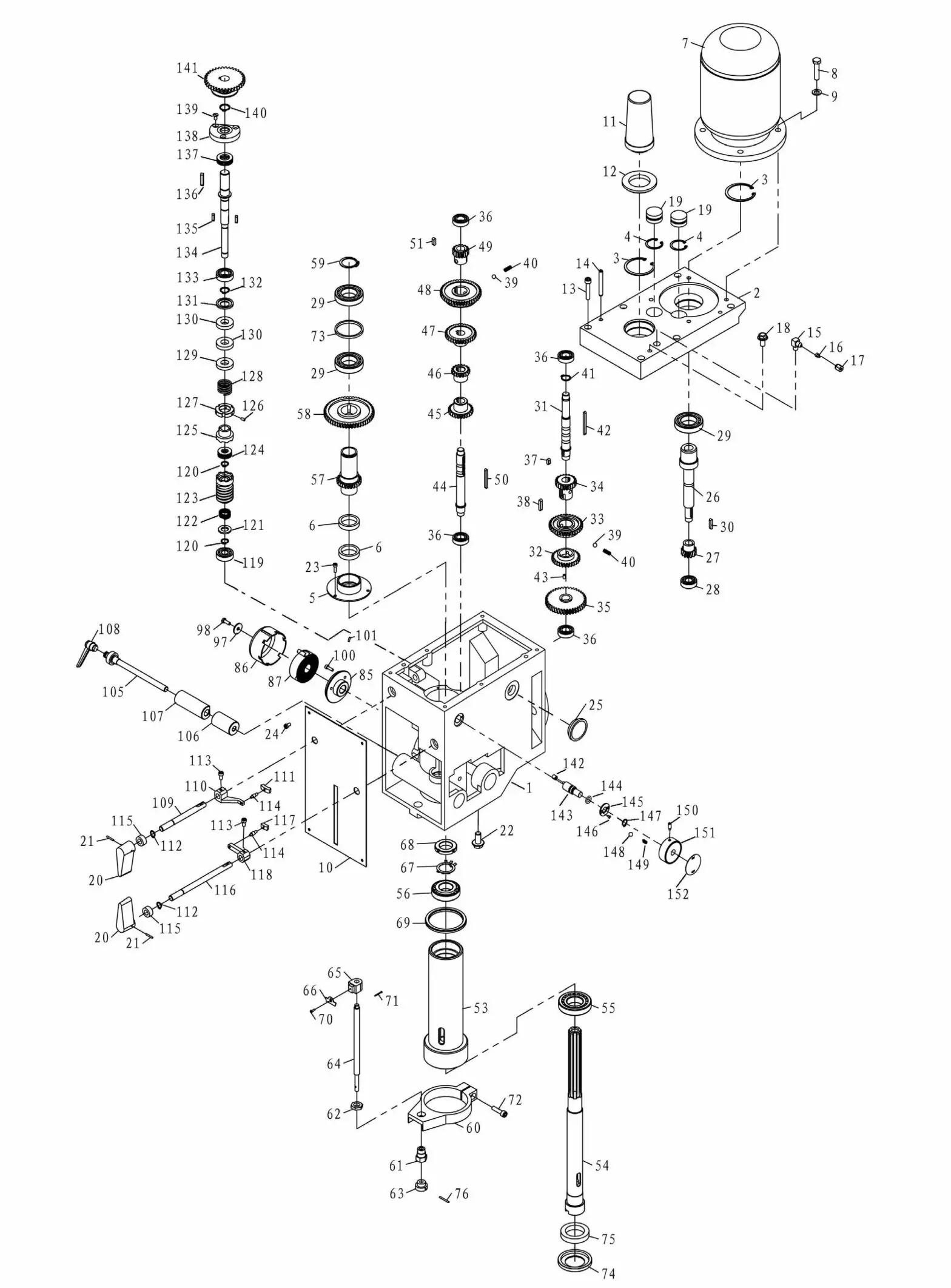
| No. | Qty. | Code | Name | No. | Qty. | Code | Name |
| I 1 | 1 | 20010B | head body | 37 | 1 | key | |
| I 2 | 1 | 20011B | head body cover | 38 | 1 | key | |
| I 3 | 2 | retaining ring | 39 | 2 | ball | ||
| I 4 | 2 | retaining ring | 40 | 2 | spring | ||
| I 5 | 1 | 20018B | airtight base | 41 | 2 | retaining ring | |
| I 6 | 2 | airtight ring | 42 | 1 | key | ||
| I 7 | 1 | motor | 43 | 4 | screw | ||
| 8 | 1 | screw | 44 | 1 | 20107B | Ill shaft | |
| I 9 | 1 | washer | 45 | 1 | 20109-B | clear | |
| I 10 | 1 | 20201 | plate | 46 | 1 | 20110-2-8 | gear |
| I 11 | 1 | 20304-1 B | arbor bolt cover | 47 | 1 | 20112-B | gear |
| 12 | 1 | 20304-2B | arbor bolt cover base | 48 | 1 | 20113-8 | gear |
| 13 | 1 | screw | 49 | 1 | 20115-B | gear | |
| 14 | 1 | pin | 50 | 1 | key | ||
| 15 | 1 | 20025B | ioint | 52 | 1 | key | |
| 16 | 1 | 20026B | sleeve | 53 | 1 | 20019 | spindle sleeve |
| 17 | 1 | 20027B | nut | 54 | 1 | 20104B | spindle |
| 18 | 1 | bolt | 55 | 1 | bearing | ||
| 19 | 2 | 20020B | cap | 56 | 1 | bearing | |
| 20 | 2 | 20307B | speed lever | 57 | 1 | 20114-B | splined sleeve |
| 21 | 2 | pin | 58 | 1 | 20116-B | gear | |
| 22 | 1 | oil plug | 59 | 1 | retaining ring | ||
| 23 | 1 | screw | 60 | 1 | 20012 | feed base | |
| 24 | 1 | screw | 61 | 1 | 20128 | support base | |
| 25 | 1 | oil pointer | 62 | 1 | 20129 | nut | |
| 26 | 1 | 20105B | I shaft | 63 | 1 | 20130 | knob |
| 27 | 1 | 20105-1-B | gear | 64 | 1 | 20131 | graduated rod |
| 28 | 1 | bearing | 65 | 1 | 20021 | fixed bolt | |
| 29 | 3 | bearing | 66 | 1 | 20132 | scale board | |
| 30 | 1 | key | 67 | 1 | lock washer | ||
| 31 | 1 | 20106B | II shaft | 68 | 1 | lock nut | |
| 32 | 1 | 20108-B | gear | 69 | 1 | 20308 | rubber washer |
| 33 | 1 | 20110-1-B | gear | 70 | 1 | screw | |
| 34 | 1 | 20111-B | gear | 71 | 1 | split pin | |
| 35 | 1 | 20106-1-B | gear | 72 | 1 | bolt | |
| 36 | 4 | bearing | 73 | 1 | 200248 | separating ring |
| No. | Qty | Code | Name |
| 74 | 1 | 20133B | oil tight cover |
| 75 | 1 | air tight | |
| 76 | 1 | pin | |
| 85 | 1 | 20118 | spring base |
| 86 | 1 | 20123 | spring cap |
| 87 | 1 | 20122 | spring plate |
| 97 | 1 | 20102 | washer |
| 98 | 1 | bolt | |
| 100 | 1 | screw | |
| 101 | 2 | pin | |
| 105 | 1 | 20124B | fixed bolt |
| 106 | 1 | 20203B | fixed tight block |
| 107 | 1 | 20202B | fixed tight block |
| 108 | 1 | adjust handle | |
| 109 | 1 | 20125B | lever shaft |
| 110 | 1 | 20022-1B | lever |
| 111 | 1 | 20204-2B | lever bracket |
| 112 | 2 | retaining ring | |
| 113 | 2 | screw | |
| 114 | 2 | 20204-3B | lever rod |
| 115 | 2 | oil seal | |
| 116 | 1 | 20126B | long lever shaft |
| 117 | 1 | 20204-1B | lever bracket |
| 118 | 1 | 20022-2B | lever |
| 119 | 1 | bearing | |
| 120 | 2 | washer | |
| 121 | 1 | washer | |
| 122 | 1 | 20209 | spring |
| 123 | 1 | 20207A | worm shaft |
| 124 | 1 | bearing | |
| 125 | 1 | 20208B | clutch base |
| 126 | 3 | screw | |
| 127 | 1 | locked nut | |
| 128 | 1 | 20205B | spring |
| 129 | 1 | 20108A | fixed sleeve |
| 130 | 2 | oil seal | |
| 131 | 1 | 20103A | washer |
| 132 | 1 | retaining ring | |
| 133 | 1 | bearing | |
| 134 | 1 | 20213A | Ⅰshaft |
| 135 | 2 | key | |
| 136 | 1 | key | |
| 137 | 1 | bearing | |
| 138 | 1 | 20104A | flange |
| 139 | 3 | screw | |
| 140 | 1 | retaining ring | |
| 141 | 1 | 20212A | gear |
| 142 | 1 | 20109A | quill |
| 143 | 1 | 20214A | lever shaft |
| 144 | 1 | O-airtight | |
| 145 | 1 | 20250 | flange cover |
| 146 | 2 | screw | |
| 147 | 1 | retaining ring | |
| 148 | 1 | steel ball | |
| 149 | 1 | spring | |
| 150 | 1 | screw | |
| 151 | 1 | 20201 | speed lever |
| 152 | 1 | 20303 | label |
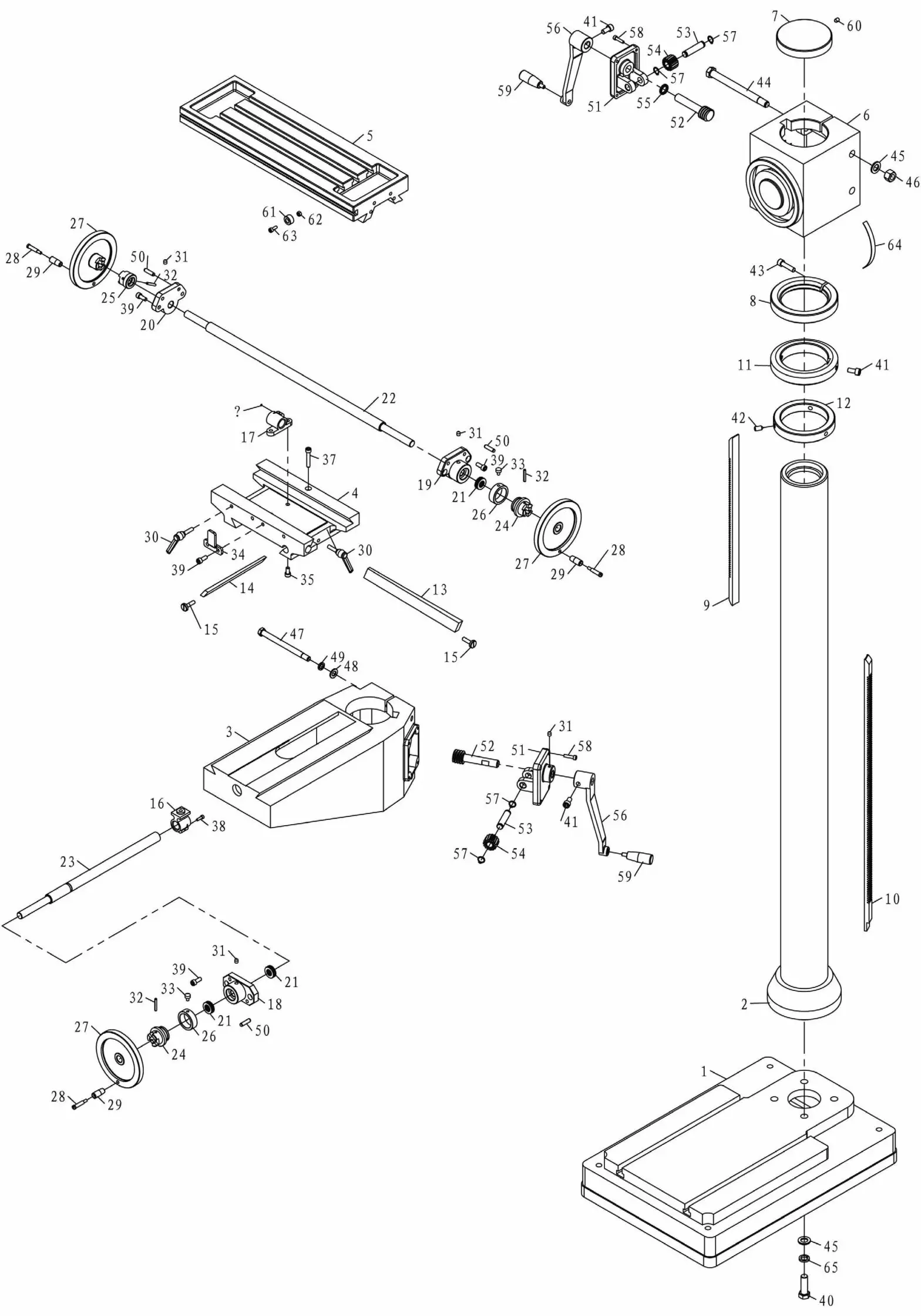
| No. | Qty. | Code | Name |
| 1 | 1 | 10002/40H | base |
| 2 | 1 | 10001/40H | column |
| 3 | 1 | 10003/40H | lifting table |
| 4 | 1 | 10005/40H | slip saddle |
| 5 | 1 | 10004/40H | work table |
| 6 | 1 | 10016/40H | elevating body |
| 7 | 1 | 10014/40 | column lid |
| 8 | 1 | 10012/40H | locked guide ring |
| 9 | 1 | 10014/40H | up rack |
| 10 | 1 | 10015/40H | low rack |
| 11 | 1 | 10011/40H | guide ring |
| 12 | 1 | 10013/40H | fixed ring |
| 13 | 1 | 10006/40H | gib strip |
| 14 | 1 | 10007/40H | gib strip |
| 15 | 2 | 10106/40 | adjust screw |
| 16 | 1 | 10203/40 | guide screw nut |
| 17 | 1 | 10202/40 | guide screw |
| 18 | 1 | 10021/40 | guide screw support |
| 19 | 1 | 10020/40 | right support |
| 20 | 1 | 10019/40 | left support |
| 21 | 4 | bearing 51103 | |
| 22 | 1 | 10008/40H | table screw |
| 23 | 1 | 10009/40H | base screw |
| 24 | 2 | 10102/40H | dial clutch |
| 25 | 1 | 10110/40 | left clutch |
| 26 | 2 | 10111/40 | graduation plate |
| 27 | 3 | 10301/40 | handwheel |
| 28 | 3 | 20305-2B/40 | screw |
| 29 | 3 | 20305-1B/40 | turn handle |
| 30 | 3 | adjust handle | |
| 31 | 5 | oil cup 8 | |
| 32 | 3 | pin 5X35 | |
| 33 | 2 | 10107/40 | screw |
| 34 | 1 | 10105/40 | fixed block |
| 35 | 2 | screw M8X16 | |
| 36 | 1 | screw M5X12 | |
| 37 | 1 | screw M8X45 | |
| 38 | 1 | screw M5X16 | |
| 39 | 8 | screw M8X20 | |
| 40 | 4 | bolt M16X50 | |
| 41 | 3 | screw M10X20 | |
| 42 | 3 | screw M10X20 | |
| 43 | 1 | screw M10X40 | |
| 44 | 2 | bolt M16X190 | |
| 45 | 3 | washer 16 | |
| 46 | 2 | nut M16 | |
| 47 | 2 | bolt M12X16 | |
| 48 | 2 | washer 12 | |
| 49 | 2 | washer 12 | |
| 50 | 6 | pin 8X30 | |
| 51 | 2 | 10017/40 | bracket |
| 52 | 2 | 10112/40 | worm shaft |
| 53 | 2 | 10113/40 | small shaft |
| 54 | 2 | helical gear | |
| 55 | 2 | 10201/40 | washer |
| 56 | 2 | 10018/40 | rock handle |
| 57 | 4 | retaining ring | |
| 58 | 8 | screw M6X25 | |
| 59 | 2 | turn handle | |
| 60 | 1 | screw M8X12 | |
| 61 | 2 | 10109/40 | fixedblocksupport |
| 62 | 2 | nut M6 | |
| 63 | 2 | screw M6X16 | |
| 64 | 1 | degree meter | |
| 65 | 1 | washer 16 | |


