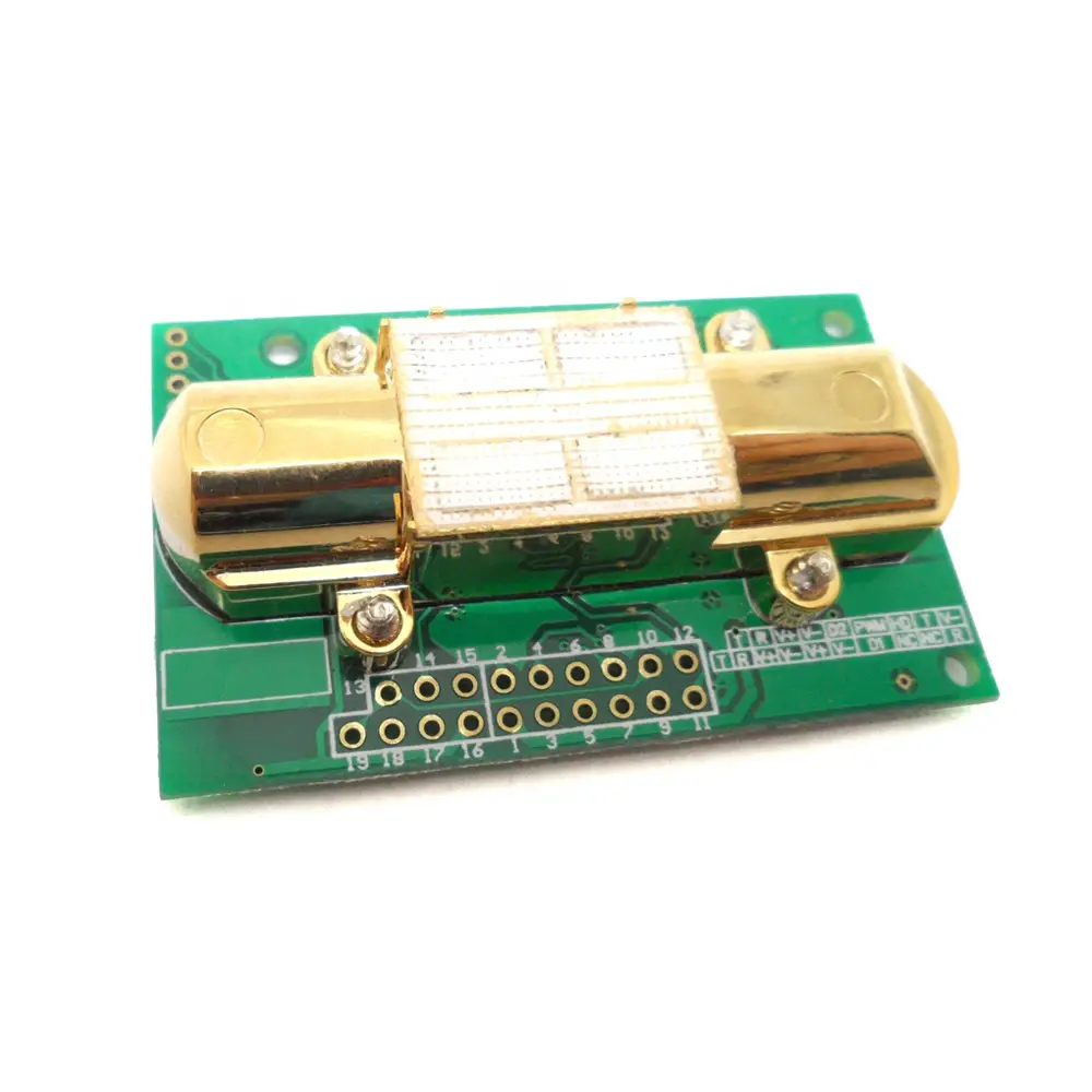
MH-Z14 Intelligent Infrared Gas Module
Profile
Main functions and features:
- High sensitivity, High resolution
- Low power consumption
- Output modes: UART, analog voltage signal, PWM wave
- Quick response
- Temperature compensation, excellent linear output
- Good stability
- Long lifespan
- Anti-water vapor interference
- No poisoning

Main technical parameters
| Working voltage | 4.5 V ~ 5.5V DC |
| Average current | < 85 mA |
| Interface level | 3.3 V |
| Measuring range | 0~5%VOL optional |
| Output signal | PWM |
| UART | |
| 0.4-2V DC | |
| Preheat time | 3min |
| Reponse Time | T90 < 90s |
| Working temperature | 0℃ ~ 50℃ |
| Working humidity | 0~95%RH |
| Weight | 15 g |
| Lifespan | >5 year |
| Dimension | 57.5×34.7×16mm(L×W×H) |
| Target Gas | Measuring Range | Accuracy | Mark |
|
Carbon Dioxide (CO2) | 0~2000ppm |
±(50ppm +5%readin g value) | Temperature compensation |
| 0~5000ppm | Temperature compensation | ||
| 0~1%VOL | Temperature compensation | ||
| 0~3%VOL | Temperature compensation | ||
| 0~5%VOL | Temperature compensation |
Structure
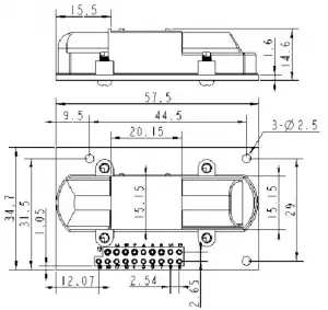
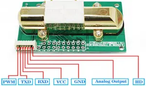
Definition for pins
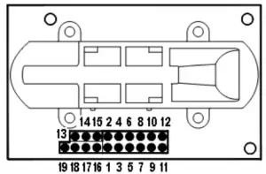
PIN | Description |
Pad1、 Pad15、Pad17 | Vin(input voltage 4.5V~5.5V) |
Pad2、Pad3、 Pad12、Pad16 | GND |
Pad4 | Vout2 (0.4~2V) |
Pad5 | Vout1 (0~2.5V) |
Pad6 | PWM |
Pad8 | HD |
Pad7、 Pad9 | NC |
Pad11、Pad14、Pad18 | UART(RXD) 0~3.3V input digital |
Pad10、Pad13、Pad19 | UART(TXD) 0~3.3V output digital |
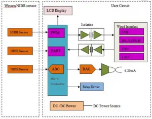
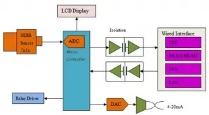
Circuit
Operating instruction
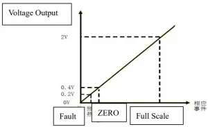
Analog output connections
The output value of Vout1 is 0-2.5V, which stands for 0 to full range.
The output value of Vout2 is 0.4-2V, which stands for 0 to full range.
Vin –5V
GND- Power Ground
Vout2-ADC input
After preheating, the value of output voltage from Vout2 represents gas concentration.
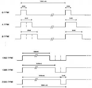
PWM output (taking PWM output from 2000ppm as example):
CO2 output range: 0ppm-2000ppm
Cycle: 1004ms±5%
High level output for beginning: 2ms (in name)
Middle of cycle: 1000ms±5%
Low level output for ending: 2ms(in name)
Account formula for CO2 concentration which gets through PWM: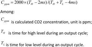
Digital connects
Vin-5V power
GND- Power Ground
RXD connect sensor TXD
TXD connect sensor RXD
You can read gas concentration via Uart, no need to calculate.
Communication protocol
- General Settings
Baud rate 9600 Date byte 8 byte Stop byte 1byte Calibrate byte no - Command
Each command or return:
Contains 9 bytes (byte 0 ~ 8) starting byte fixed 0 XFF
command contains sensor number (factory default to 0 x01) to check and endCommand List:0x86 Gas concentration 0x87 Calibrate zero point(ZERO) 0x88 Calibrate span point(SPAN) Read gas concentration
Send command Byte0
Byte1 Byte2 Byte3 Byte4 Byte5 Byte6
Byte7 Byte8 Starting byte
Sensor No. command – – –
– – Check value 0XFF
0x01 0x86 0x00 0x00 0x00 0x00
0x00 0x79 Return value
Return
Byte0
Byte1 Byte2 Byte3 Byte4 Byte5 Byte6
Byte7 Byte8 Starting
byte
command High level concentration Low level concentration – – –
– Chec k value
0XFF 0x86 0x02 0x60 0x47 0x00 0x00
0x00 0xD1 Gas concentration= high level *256+low level
Calibrate zero point
Send command
Byte0
Byte1 Byte2 Byte3 Byte4 Byte5 Byte6
Byte7 Byte8 Starting
byte
Sensor No. command – – – – – Check value
0XFF
0x01 0x87 0x00 0x00 0x00 0x00 0x00 0x78
No return value
Calibrate span point
Send command
Byte0
Byte1 Byte2 Byte3 Byte4 Byte5 Byte6 Byte7
Byte8 Starting
byte
Sensor No. command High level span point
Low level span point
–
– –
Check value 0XFF 0x01 0x88 0x07 0xD0 0x00 0x00 0x00
0xA0 No return value
- Calibration and calculation
The checksum = (invert (byte 1 +… + 7)) + 1
Reading gas concentration:Send command
Byte0
Byte1 Byte2 Byte3 Byte4 Byte5 Byte6 Byte7
Byte8 Starting
byteSensor No. command – – – – –
Check value 0XFF
0x01 0x86 0x00 0x00 0x00 0x00 0x00
0x79 Except byte 0 ,add the other bytes together
0x1 + 0x86 + 0 + 0 + 0 + 0 + 0 = 0x87
Get the value from the first step, then invert it.
0xff – 0x87 = 0x78
The second value plus one
0x78 + 0x01 = 0x79
Program :C languagechar getCheckSum(char *packet)
{char i, checksum; for( i = 1; i < 8; i++)
{
checksum += packet[i];}
checksum = 0xff – checksum;
checksum += 1;
return checksum;
}
Notes for maintenance
7.1 The sensor should be calibrated regularly. The cycle time is better to be no more than 6 months.
7.2 Do not use the sensor in the high dusty environment for long time.
7.3 Please use the sensor with correct power supply.
7.4 Forbidden to cut the sensor pin.
MH-Z14 Intelligent Infrared Gas Module User’s Manual – Download [optimized]
MH-Z14 Intelligent Infrared Gas Module User’s Manual – Download


