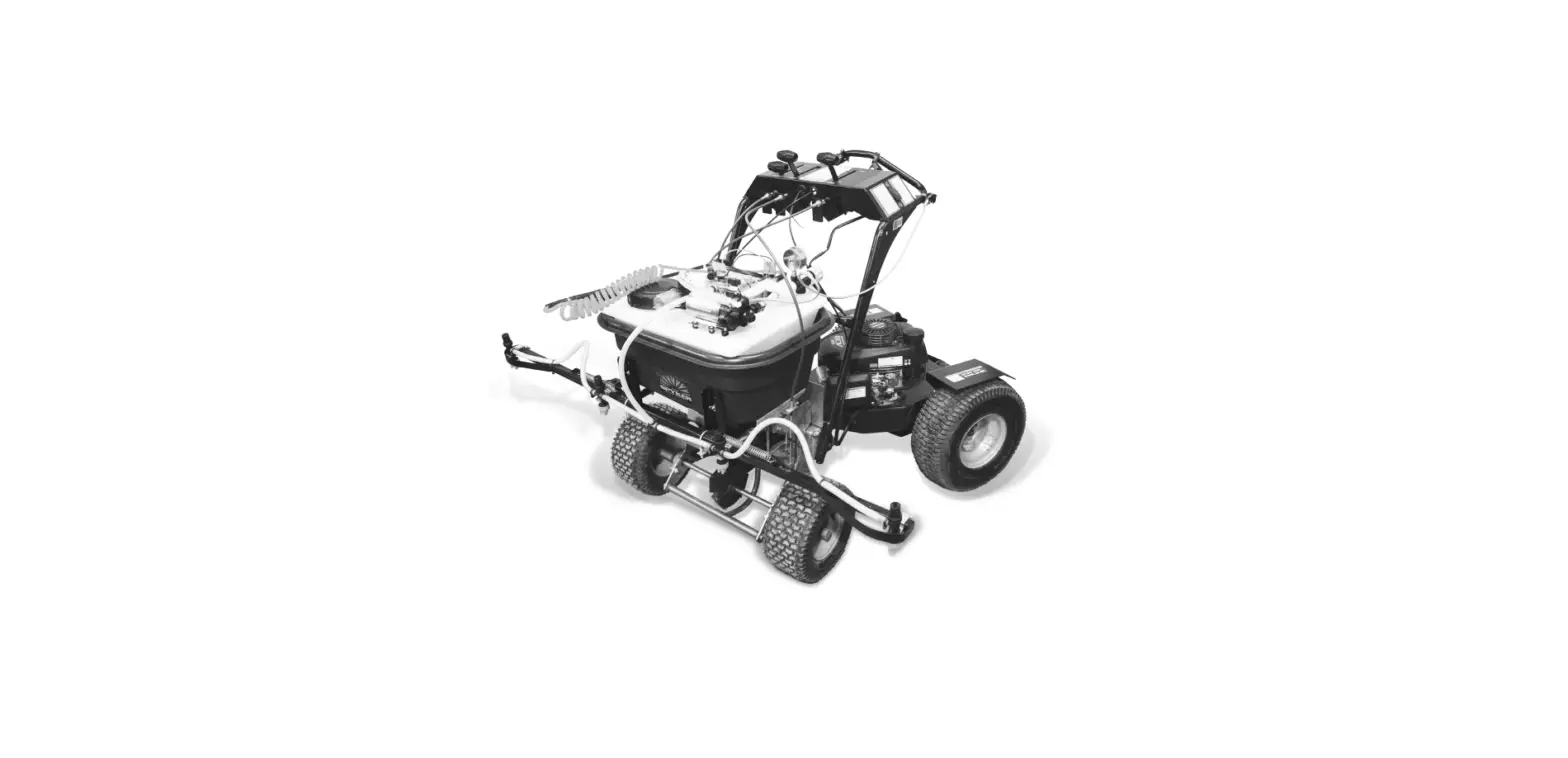

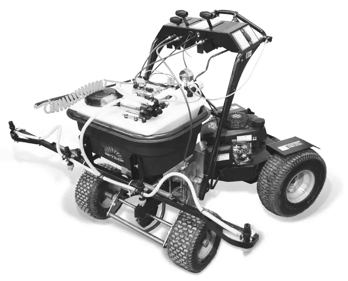
SPYKER SPYDSB-9G Drop-In Sprayer with Boom
IMPORTANT This manual contains information for the safety of persons and property. Read it carefully before assembly and operation of the equipment!
OPERATE SAFELY
Read Before Using:
Pesticides can cause personal injury and harm the envir-onment when used improperly. Be sure to follow label recommendations concerning safety and disposal.
Note: Observe all safety precautions including wearing of protective clothing and equipment.
COMPATIBILITY
The SPYDSB-9G is designed to fit the following spreaders: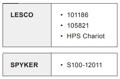
SET-UP PROCEDURE
The SPYDSB-9G was pressure tested prior to shipment. Some components were disassembled for packaging and shipment. The basic set-up procedure is as follows:
- Remove the spray wand from inside the tank.
- Remove all contents from the box.
- Cut the plastic ties holding the boom sections together.
- Report any missing or damaged items to your dealer immediately.
NOTE: The pink liquid residue in the tank is RV antifreeze. Flush out the tank before use.
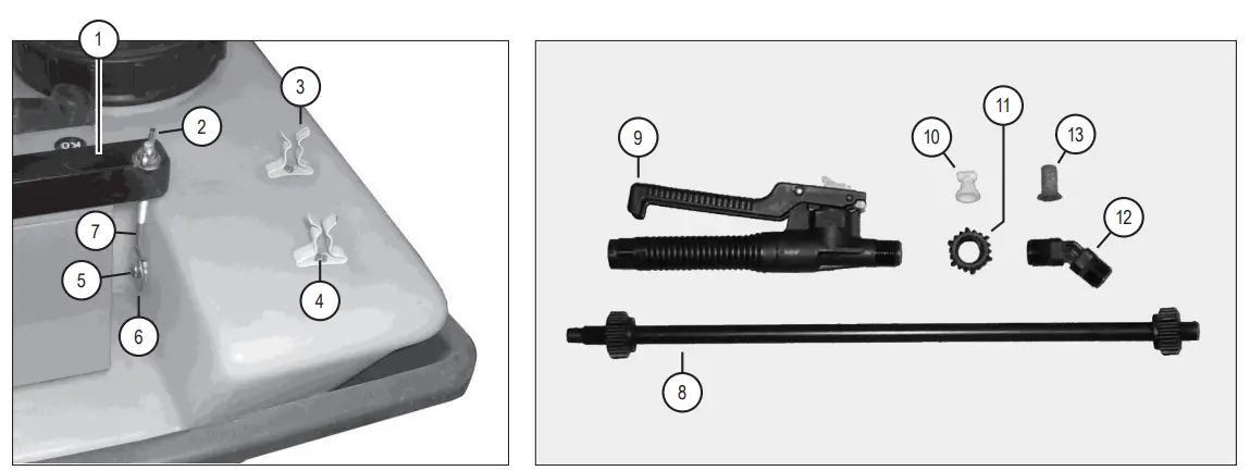
BATTERY AND SPRAY WAND MOUNTING HARDWARE 
| No. | Part # | Qty | Description |
| 1 | 1019634 | 1 | Angle Bracket |
| 2 | 1019635 | 2 | Wing Nut |
| 3 | 1019636 | 2 | Mounting Clip |
| 4 | 1019637 | 2 | Screw #6 x 1/2″ |
| 5 | 1019638 | 2 | Pan Head Screw |
| 6 | 1019639 | 2 | Fender Washer |
| 7 | 1019640 | 2 | Eye Bolt |
| 1019641* | 2 | Eye Bolt *Optional Alternate (H.C. Battery) |
| 8 | 1019691 | 1 | Extension Wand |
| 9 | 1019692 | 1 | Trigger Jet Valve |
| 10 | 1019693 | 1 | Turbo TeeJet Nozzle Tip |
| 11 | 1019694 | 1 | Cap Nut |
| 12 | 1019695 | 1 | Angle Adapter |
| 13 | 1019696 | 1 | 50 Mesh Screen |
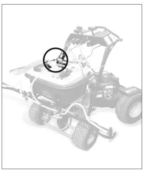
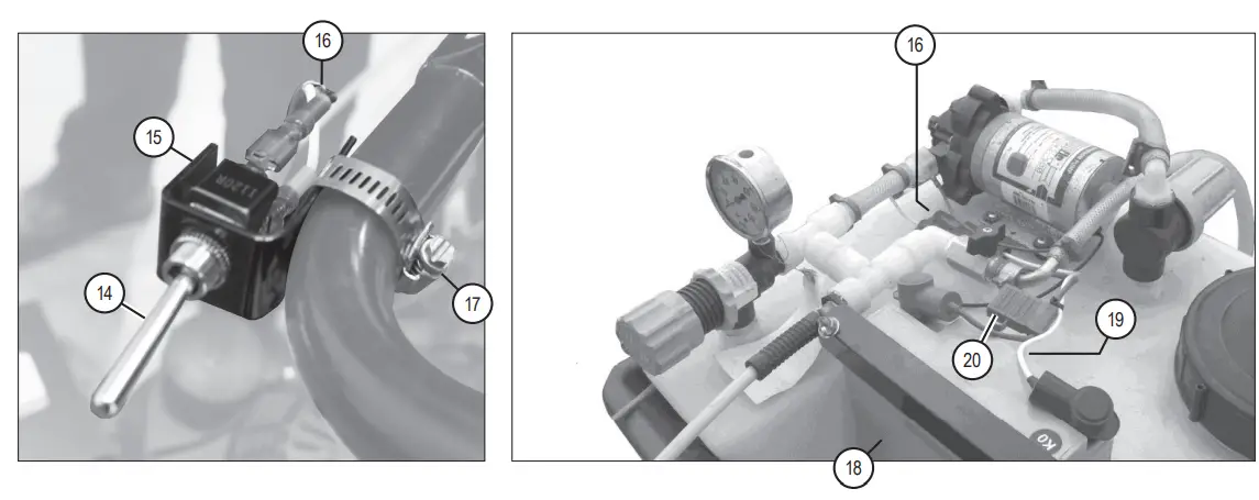
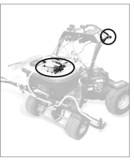
ELECTRICAL COMPONENTS
| No. | Part # | Qty | Description |
| 14 | 1019642 | 1 | Toggle Switch |
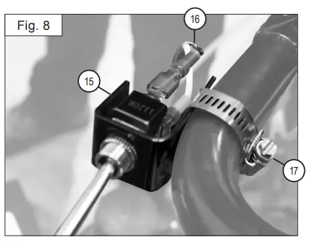
| 15 | 1019643 | 1 | Switch Bracket |
| 16 | 1019644 | 1 | Pump / Switch Wiring Assembly |
| 17 | 1019645 | 1 | Screw Clamp |
| 18 | 1019646 | 1 | Battery |
| 1019647 | 1 | Battery *High Capacity |
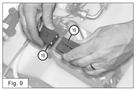
| 19 | 1019648 | 1 | Battery Wiring Assembly |
| 1019649* | 1 | Battery Wiring Assembly *Optional H.C. Battery |
| 20 | 1019650 | 1 | Fuse Holder |
| N/A | 1019651 | 1 | 20 Amp Fuse |
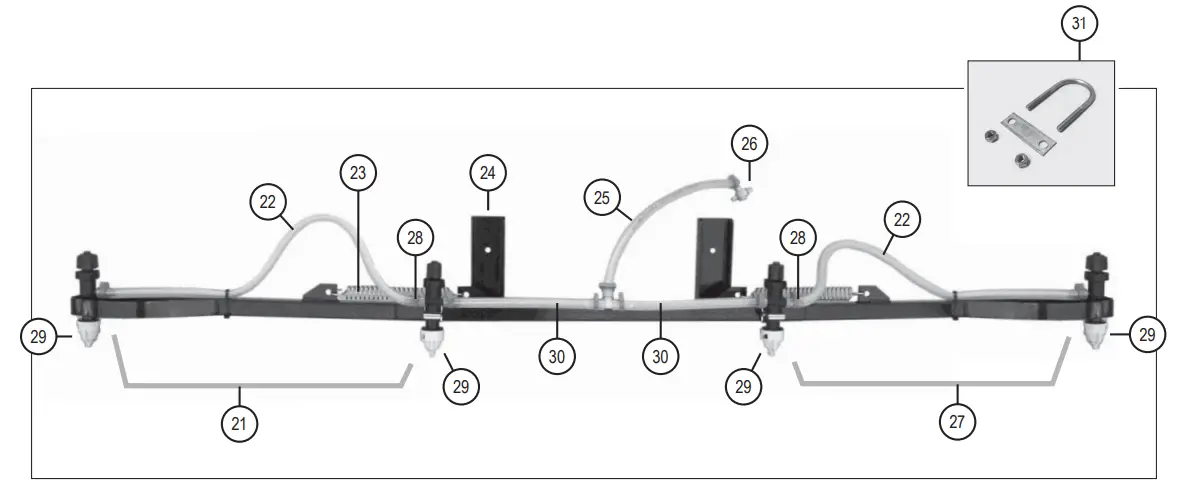
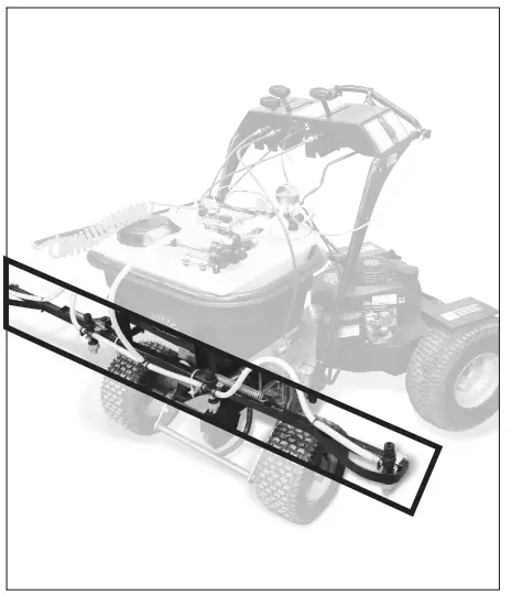
BOOM COMPONENTS DIAGRAM
| No. | Part # | Qty | Description |
| 21 | 1019697 | 1 | Right Boom Section |
| 22 | 1019698 | 2 | Hose, 3/8″ ID x 24″ |
| 23 | 1019699 | 2 | Spring, Stainless Steel |
| 24 | 1019700 | 1 | Center Boom Section |
| 25 | 1019701 | 1 | Hose, 3/8″ ID x 21″ |
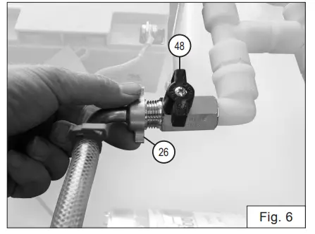
| 26 | 1019661 | 1 | Hose Barb Wing Nut Assy. 3/8″ |
| 27 | 1019702 | 1 | Left Boom Section |
| 28 | 1019703 | 2 | Hinge Bolt, Lock Nut, 3/8″ |
| 29 | 1019704 | 4 | Nozzle Assembly, See Page 8 |
| 30 | 1019705 | 2 | Hose, 3/8″ ID x 9″ |
| 31 | 1019618 | 1 | Bag; U-Bolts and Nylon Locknuts |
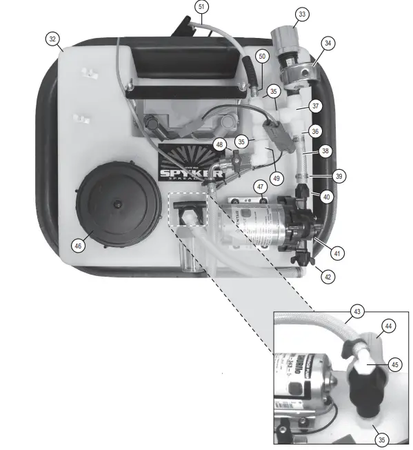
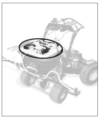
TANK & PLUMBING
| No. | Part # | Qty | Description |
| 32 | 1019662 | 1 | Poly Tank, 9 Gallon |
| 33 | 1019663 | 1 | Regulator |
| 34 | 1019664 | 1 | 0-60 SS Liquid Filled Gauge |
| 35 | 1019665 | 4 | 1/2″ Close Nipple Hex |
| 36 | 1019666 | 4 | 1/2″ MPT x 1/2″ Barb (NOTE: Two of the four Barbs are not visible in this photo as they are located inside the tank) |
| 37 | 1019668 | 2 | 1/2″ Female Tee |
| No. | Part # | Qty | Description |
| 38 | 1019669 | 1 | Clear Braid Hose 1/2″ ID x 3.5″ |
| 39 | 1019670 | 4 | Easy Seal Clamp For 1/2″ ID Hose |
| 40 | 1019671 | 1 | 1/2″ FPT x 1/2″ Barb Straight Swivel |
| 1019672 | 1 | 1/2″ ORS x 1/2″ Barb Straight *Optional Part |
| 41 | 1019673 | 1 | Shurflo Pump 3 Gpm |
| 1019674 | 1 | FloJet Pump, 5 GPM *Optional Part |
| 42 | 1019675 | 1 | 1/2″ FPT x 1/2″ Barb Elbow Swivel |
| 1019676 | 1 | 1/2″ ORS x 1/2″ Barb Elbow *Optional Part |
| 43 | 1019677 | 1 | Clearbraid Hose 1/2″ ID x 10″ |
| 44 | 1019713 | 1 | Strainer 1/2″ 50 Mesh, with cover |
| 45 | 1019681 | 1 | 1/2″ MPT x 1/2″ Barb Elbow |
| 46 | 1019682 | 1 | 6″ Female Tank Lid With Vent |
| 47 | 1019683 | 4 | # 10-24 x 1″ SS Machine Screw |
| 48 | 1019684 | 1 | Ball Valve 1/2″ FPT x 1/2″ MPT |
| 49 | 1019685 | 1 | 1/2″ Street Ell |
| 50 | 1019686 | 1 | 1/2″ x 1/4″ NPT Reducer Bushing |
| 51 | 1019687 | 1 | Retractable Hose 1/4″ x 10′ |
| Not Illustrated: | |||
| N/A | 1019714 | 1 | 50 Mesh Screen |
| N/A | 1019715 | 1 | Strainer Bowl Gasket |
| N/A | 1019688 | 1 | Hose 1/2″ ID x 15″ (Inside Tank, Suction Line) |
| N/A | 1019689 | 1 | Hose 1/2″ ID x 16″ (Inside Tank, Return Line) |
| N/A | 1019690 | 1 | Screw Clamp, SS (Inside Tank, Suction Line) |
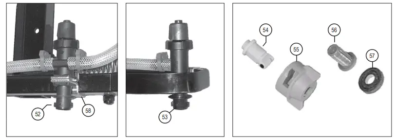
NOZZLE ASSEMBLY
| No. | Part # | Qty | Description |
| 52 | 1019706 | 2 | Dripless Nozzle Body, Double w/ Cap |
| 53 | 1019707 | 2 | Dripless Nozzle Body, Single w/ Cap |
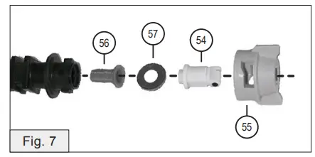
| 54 | 1019708 | 4 | Turbo TeeJet Air Induction Nozzle |
| 55 | 1019709 | 4 | Quickjet Cap |
| 56 | 1019710 | 4 | Screen |
| 57 | 1019711 | 4 | Washer |
| 58 | 1019712 | 4 | Vari-Spacing Clamp |
Assembly
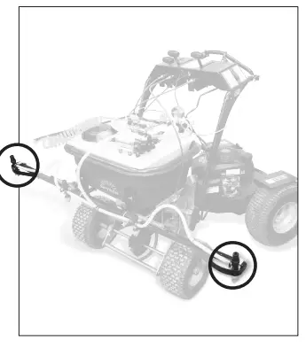
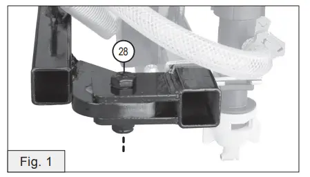
- Utilizing the holes illustrated here, align the boom arms to the center section. Attach using the 3/8” hinge bolts and locknuts (28).
NOTE: Do not tighten fully! Allow movement.
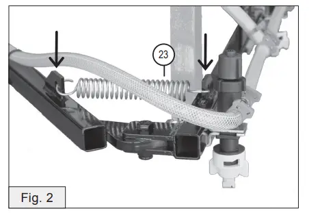
- With the boom arms folded closed, install the springs (23) on the spring mounting tabs.

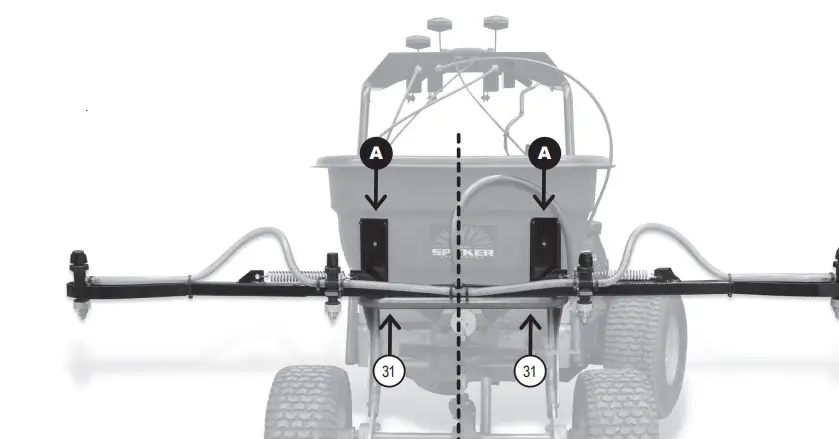
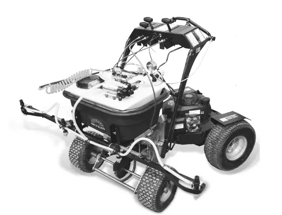
- Add the boom to the front of the spreader.
Rest the opened boom assembly on the extended front tubular frame of the spreader, as illustrated.
NOTE: Center the vertical mounting brackets (A).
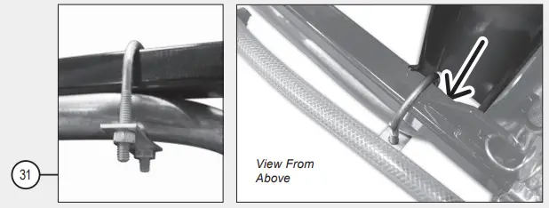
Bolt the boom to the spreader frame using hardware from the provided U-bolt bag (31).
NOTE: When viewed from above, be mindful that the U-bolt must pass through the opening of the vertical mounting brackets (A).
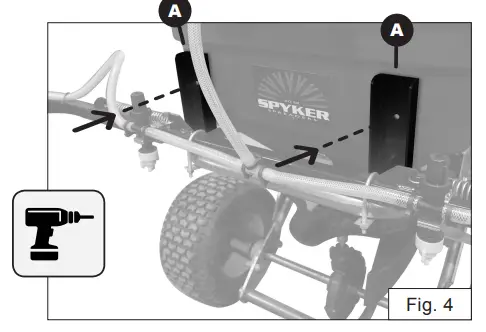
- Using the boom support brackets (A) as a template: Drill through the mounting openings, creating two 1/4 inch diameter holes in the hopper.

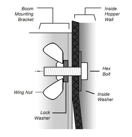
Place the 1-1/2 inch diameter washers on the inside of the hopper wall and insert the 1/4-20 hex head bolts in the holes. The bolt heads should be inside the hopper. They should be snug and will need to be screwed into the holes. The front face of the hopper will not be 100% flush with the boom mounting brackets.
NOTE: Do not over-tighten the wingnut. The small lockwashers and wingnuts are used to secure the boom while in use. See illustration below
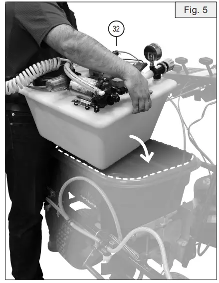
- Clean all debris from the spreader hopper. Place the empty tank assembly (32) in your spreader hopper with the battery mounted toward the rear.

- Hook up the boom hose wingnut (48) to the boom line valve (26).

- Install the sprayer nozzles (54), screens (56), washers (57) and caps (55).

- Install the handle thumb switch (15) with a screw clamp (17). Plug in the switch wiring (16).

- Install the pump wiring assembly clips to the switch spades and connect the battery wiring assembly (19).

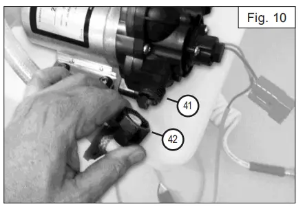
- Connect swivel elbow fitting (42) to the pump inlet port (41).

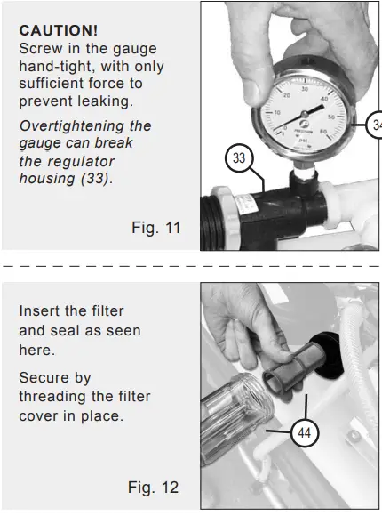
- Install the pressure gauge (34) and filter assembly (44).

General Operation & Maintenance
The sprayer pump is turned on and off by the thumb switch mounted on the handlebar of the spreader. Each dripless nozzle body has a special shut-off cap. The nozzle body requires 5 psi of system pressure to open, thus keeping the nozzles from dripping when the pump is off. The nozzles can be completely shut off by turning the cap clockwise. The operator can turn off individual nozzles as needed. The hand spray wand is activated by closing the boom line valve (ball valve on top of the tank) to turn off flow to the boom. To drain the tank of unused liquids, remove the spray tip from the wand and pump the remaining liquid into the proper receptacle.
- Clean pump filter daily.
- Clean tip screens regularly.
- Prevent from freezing.
- Adjust hinge lock nut tension as necessary.
- Flush with water after each use.
- Lubricate hinges with grease.

INITIAL START-UP & PRESSURE TESTING
- Turn the pressure regulator knob counter-clockwise all the way.
- Put about one gallon of water in the tank for testing.
- Be sure that the spray line valve is turned off.
- Turn on the handlebar thumb switch. You should hear the pump running and see water moving through the hoses.
- Slowly turn the pressure regulator knob clockwise to increase the pressure. You should notice movement of the needle on the pressure gauge. Adjust the pressure to 30 psi for testing.
- With the spray wand assembled, operate the trigger valve and check it for leaks. Note the trigger lock. Also adjust the nozzle and angle adapter orientation to the desired position.
- Turn off the switch. Turn on the boom line valve and all four caps on the top of each boom nozzle body.
- Turn on the switch and observe the spray pattern from each boom nozzle. Check the entire boom assembly for leaks.
- Flush out the water and antifreeze. Once the unit has been pressure tested and you are familiar with its operation, you can begin the calibration procedure.
Battery Charging
The SPYDSB-9G’s battery is a sealed, maintenance-free 12-volt battery. Charging at a low rate (3 amp max.) with an automotive quality battery charger will extend battery life.
A 110-volt powered plug-in battery charger is available as an optional accessory to recharge the battery when not in use. The battery can also be recharged by the service truck’s charging system by using the optional vehicle charging kit.
NOTE: A charger is not included in this kit, however, the following optional accessories are available:
KSP18-TCG: 12-Volt Truck Charger
KSP18-C12G: 120V / 60Hz US/CAN Mains 12-Volt Charger
SPRAY NOZZLE SETTINGS
The SPYDSB-9G is equipped with dripless nozzle bodies and special shut-off caps. Each nozzle body requires 5 psi of system pressure to open. This keeps the nozzles from dripping when the pump is turned off.
The nozzle bodies can be completely shut off by turning the cap clockwise, as shown. This allows the operator to turn off individual nozzles when spraying with less than the full boom width is desired.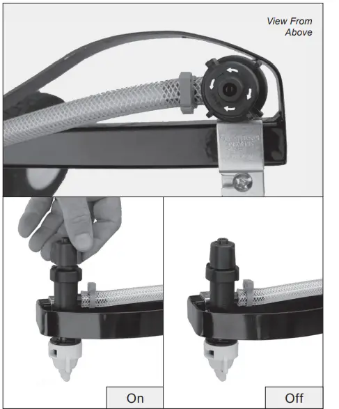
Calibration
The SPYDSB-9G is equipped with a Hypro DeflecTip wide-angle flat flood nozzle. The table below will serve as a ref-erence for application rates. A working pressure of 15-20 psi will provide adequate coverage. The nozzle should be adjusted to provide a 60-65 inch spray width with a 4-6 inch overlap of the previous spray pass.
| Hypro Nozzle | Pressure | Capacity | Gallons per 1000 Sq. Ft. | |||
| Number | PSI | GPM | 2 mph | 3 mph | 4 mph | 5 mph |
|
30DT7.5 | 10 | 0.8 | 0.9 | 0.6 | 0.4 | 0.3 |
| 15 | 0.9 | 1.0 | 0.7 | 0.5 | 0.4 | |
| 20 | 1.1 | 1.2 | 0.8 | 0.6 | 0.5 | |
| 30 | 1.3 | 1.5 | 1.0 | 0.7 | 0.6 |
Confirming Application Rate
Because walking speeds vary, it is always best to perform a field test to confirm the application rate. The procedure is simple:
- Measure an area at least 10,000 square feet.
- Fill the tank with water.
- Spray the measured area at 20 psi and at a comfortable sustainable walking speed.
- Refill the tank from a calibrated container keeping track of the amount needed to refill the tank.
- Divide the number of gallons used by the square footage of the area sprayed (Expressed in 1000 square foot increments).
- Since the tank holds 9 gallons, divide 9 by the result to obtain the expected coverage per tank full.
Example: 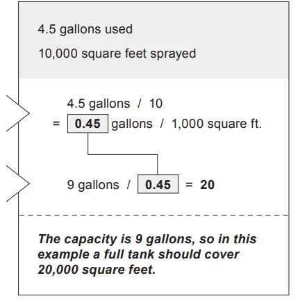
Troubleshooting
READ BEFORE USING
| Problem | Possible Cause | solution |
| Pump runs, but little or no flow | Battery drained | Recharge battery |
| Tank empty | Refill tank | |
| Filter clogged | Clean filter screen | |
| Filter bowl not on tight | Tighten filter | |
| Filter gasket faulty or missing | Check / Replace gasket | |
| Broken fitting or hose | Repair as necessary | |
| Pump needs repair | Repair as necessary | |
| Plugged intake line | Remove obstruction | |
| Pump has lost prime | Re-prime the pump by backing the Pressure Regulator all the way out. |
| Pump will not turn on | Battery dead | Recharge battery |
| Loose or faulty connection | Repair as necessary | |
| Faulty switch | Repair as necessary |
| Not all nozzles spraying | Caps on nozzle bodies turned off | Turn all caps to the ON position |
| Nozzle screen is plugged | Clean all nozzle screens |
Spreader Mate Truck Charger
The charger allows the sprayer battery to be recharged from a truck charging system in between jobs.
Included is 20 feet of 10-gauge x 2 wire, 40 amp circuit breaker, battery wire connectors, and a quick-connect modular plug for the battery.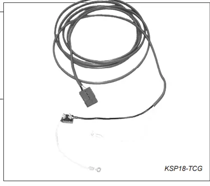
Spare Spreader Mate Battery
One battery can be charging while another battery is in use. The spare battery comes with battery wire connectors, fuse assembly and a quick-connect modular plug.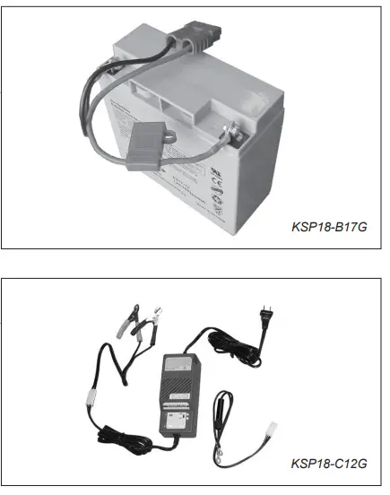 ACCUMATE CHARGER
KSP18-C12G
110-Volt powered plug-in charger for overnight recharging. This is a top quality charger designed specifically for AGM batteries.
TRUCK STAND
KSP18-TSG
This rugged steel frame mounts easily to the truck securing the sprayer tank assembly when not in use.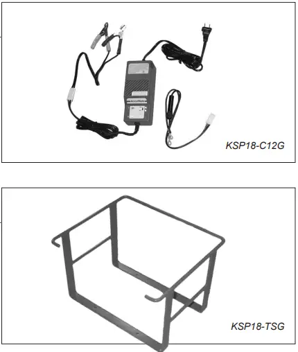
Service
QUALITY CONTINUES WITH QUALITY SERVICE
If you have installation questions, are missing parts or need replacement parts, don’t go back to the store! Please find your product serial number and model number, then contact our Customer Service department:
In North America and Canada call Toll-Free: 800-972-6130
Chat online: www.spyker.com
WARRANTY
1 YEAR LIMITED WARRANTY
This is warranted to the original purchaser only. Spyker will replace parts with defects in materials and workmanship, for a period of one year from the date of purchase.
The battery and the pump elastomers, which are considered normal wear items, carry a 90-day warranty against defects in materials and workmanship.
Spyker Spreaders will not be liable for any loss, damage or expense including, but not lim-ited to, consequential or incidental damages, arising from the operation, condition or use of the item. The sole and exclusive remedy against Spyker Spreaders being the replacement of the defective parts. This warranty gives you specific legal rights, and you may also have other rights which vary from state to state.
This express warranty, which is applicable only to the original purchase, is in lieu of and excludes all other warranties, whether expressed or implied by operation of law or otherwise, including any warranty of merchantability or fitness for particular purpose.
SPYKER SPREADERS Jeffersonville,
IN 47130 USA
Phone: 800.972.6130
www.spyker.com


