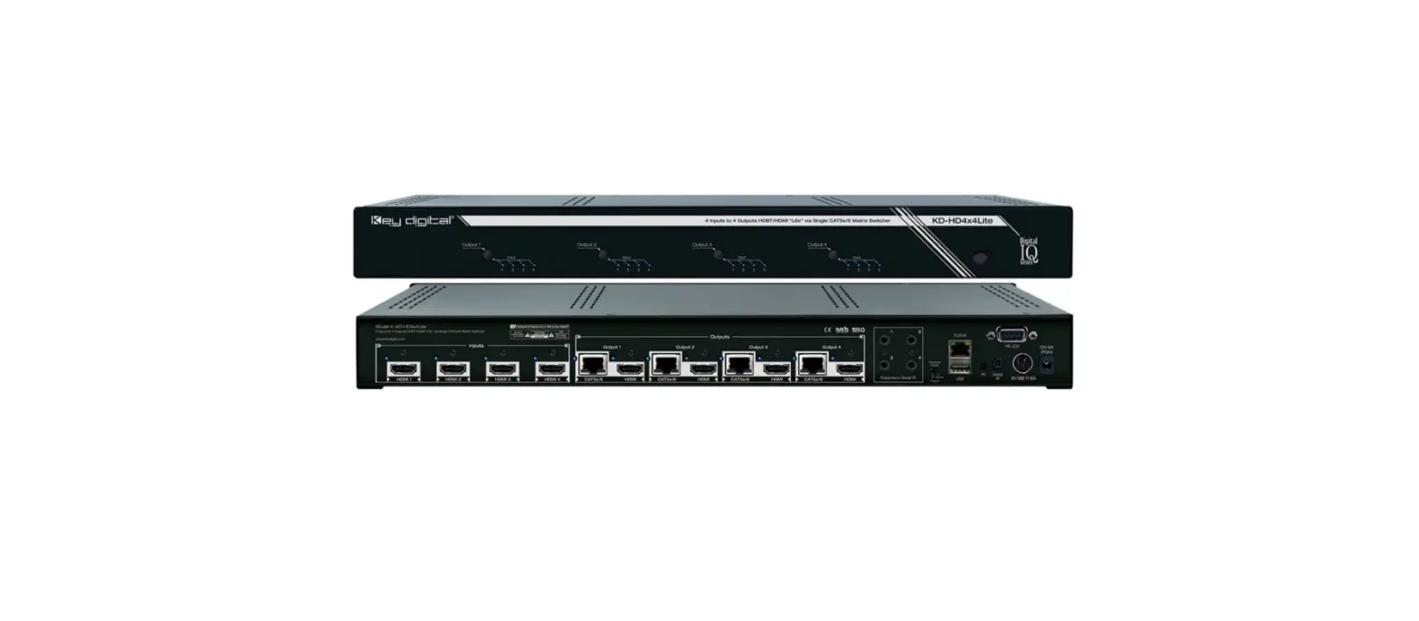
key digital KD-HD4x4 6×6 8×8 Lite HDMI-Dvi Distribution AMP Switch
Key Digital®, led by digital video pioneer Mike Tsinberg, develops and manufactures high quality, cutting-edgetechnology solutions for virtually all applications where high quality video imaging is important. Key Digital® is at the forefront of the video industry for Home Theater Retailers, Custom Installers, System Integrators, Broadcasters, Manufacturers, and Consumers.
Key Digital® Systems: 521 East 3rd Street: Mount Vernon, NY 10553
Phone : 914.667.9700
Fax : 914.668.8666
Web : www.keydigital.com
About KD-HD4x4/6×6/8x8Lite
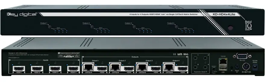
Key Digital® Digital IQ Series™ KD-HD4x4/6×6/8x8Lite are HDBaseT® Lite HDMI Matrix Switchers capable of switching up to 8 HDMI Video Sources/Inputs to up to 8 Independent Zones/Outputs via Single CAT5e/6.
Advanced HDMI® Features
- 3D – Capability to pass 3D stereoscopic signal formats
- 4K – 4096×2160/24 video resolution support for commercial applications such as Digital Movie Theaters, CAD, Post Production, Graphics, etc.
- Audio Return Channel (ARC) – Allows audio to be returned from display back to HDMI source for amplification and display
Key Features
- Features both HDMI and CAT5e/6 (RJ45) outputs, both are active simultaneously
- Transmits 1080p/60, 1080p/24, 1080i, 720p signals up to 210 ft. Transmits 4k/Ultra HD signals up to 120 ft. when used with KD-CATHD250POHRx Receiver extenders and approved Key Digital CAT5e/6 cabling. Compatible with third-party CAT5e/6 with lesser distance performance.
- Supports all SD, HD, and VESA resolutions up to 1080p (60Hz & 50Hz), 4K/Ultra HD & ARC
- Internal EDID Library features 12 default EDID configurations, in addition to Native EDID data for any Output/Display
- Full Buffer™ Technology – Full matrix buffering of HDCP and EDID for seamless switching and viewing of any source/input to any display/output, regardless of multiple output viewing relation › TMDS re-clocking – support long HDMI or CAT5e/6 connections and daisy chain configurations › RJ45 outputs utilize the HDBaseT® format Control routing enables bi-directional IR and RS-232 control signal extension
- Serial IR, Optical IR, Front Panel & RS-232 control. Supports major control systems such as Compass Control®, AMX®, Control4®, Crestron®, RTI®, Universal®.
- Includes 4/6/8 KD-CATHD250POHRx Receiver Extenders
- Fully automatic CAT5e/6 cable equalization
- 8/12/16 active outputs (4/6/8 HDMI/DVI and 4/6/8 CAT5e/6) enable flexible integration
- Supports switching of lossless compressed digital audio:
- Dolby® TrueHD, Dolby® Digital Plus and DTS™-HD Master Audio
Accessories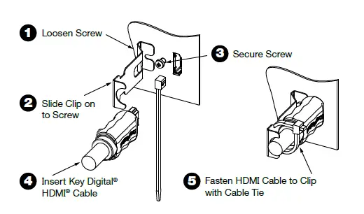
- 4/6/8/ KD-CATHD250POHRx Receiver Extenders › Two external power supplies. Matrix: +6V/11.6A (70W); KD-CATHD250POHRx:+12V/6A (70W)
- IR Remote control; HDMI Cable Clips (8/12/16); 6 ft. USB Data Cable
Rack Mounting:
Secure the rack ears to each side of the KD-HD4x4/6×6/8x8Lite with the supplied hardware, then, fasten the unit to the rack rails with the included machine screws
Rear Panel Connections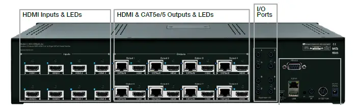
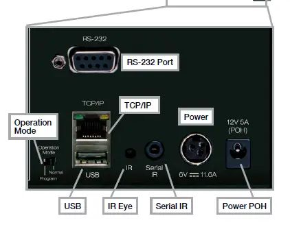
- HDMI Inputs: Located on the left side of the back panel. The Inputs have a blue LED that will illuminate when a source is connected and synced.
- HDMI & CAT5e/6 Outputs: Located in the middle of the back panel. The Outputs have a blue LED that will illuminate when a output device is connected and synced.
- The RS-232, Serial IR, Optical IR Sensor, Operation Mode Switch, TCP/IP, USB and Power connections are located on the right side of the back panel.
- I/O Ports: Located to the right of the Outputs.
- The Operation Mode switch is used to update the unit’s firmware, which is done via RS-232, USB or TCP/IP. The firmware version as well as all RS-232 commands is available through the RS-232 command ‘H’. A detailed list of RS-232 commands is available later in this guide.
- If newer firmware is made available, complete updating instructions will be included with it. Check the Key Digital website for any firmware updates.
Front Panel Buttons and LEDs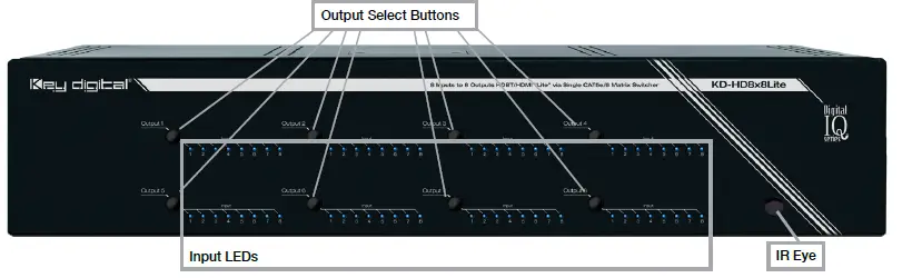
- There are 4/6/8 Output buttons along the front panel.
- Pressing an output button will select the next HDMI input.
- A blue LED will indicate which Input has been selected for each Output.
- There is also an Optical IR window located on the right side of the front panel for IR remote control signals.
Application Example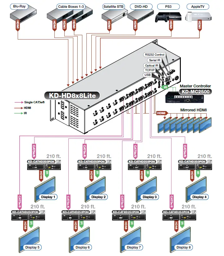
Quick Setup Guide
- Begin with the KD-HD4x4/6×6/8x8Lite and all input/output devices turned off and power cables removed.
- Connect HDMI sources to the appropriate input ports on the KD-HD4x4/6×6/8x8Lite.
- Connect CAT5e/6 outputs to the KD-CATHD250POHRx extenders via CAT5e/6 cables, then connect the extenders to the output devices (display, projector, AV Receiver, etc).
- Connect HDMI outputs to the appropriate output device (outputs will mirror CAT5e/6).
- Connect both power supplies (one for the Matrix and one for the POH Extenders) to the KDHD4x4/ 6×6/8x8Lite and all other input and output devices and turn them on.
- Operate the KD-HD4x4/6×6/8x8Lite switcher via front panel buttons, IR Remote, Serial IR or RS-232 control.
Operation:
- After performing the setup above, the unit is ready for operation.
- There are several options for controlling the unit. Commands can be issued via IR remote control,
- RS-232, TCP/IP or by using the front panel buttons. Note that the advanced commands are available only via the RS-232 protocol
KD-CATHD250POHRx Baluns
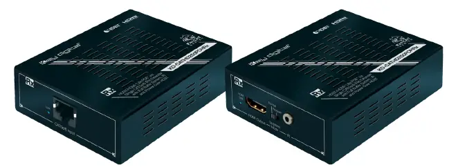
If you will be utilizing the KD-CATHD250POHRx extender, please follow this procedure.
- One CAT5e/6 UTP or STP cable needs to be used.
- Use the shortest possible HDMI cable when connecting the Extender to the Display. Key Digital recommends cables 6 ft. or shorter for optimum performance.
- Ensure the CAT cable is run directly from the switcher to the Extender.
- Do not use patch panels, punch downs, keystones, couplers, wall plates, etc..
- Key Digital recommends the use of CAT5e/6 STP cable with shielded RJ45 connectors for optimum performance and distances from your Extender
Extending and Routing Control Signals
- The KD-HD4x4/6×6/8x8Lite feature powerful and useful control routing features. The switchers have the ability to matrix control signals just like they can audio and video signals.
- KD-HD4x4/6×6/8x8Lite can consolidate incoming IR/RS-232 signals to control any display/output connected via CAT5/6 or via HDMI (control signal extension via HDMI only available with Key Digital Commercial HiFi ProS cables).
- KD-HD4x4/6×6/8x8Lite can consolidate incoming IR/RS-232 signals to control any source/input connected via HDMI, with Key Digital’s Commercial HiFi ProS cables.
- IR and RS-232 control signals are bi-directional, and may flow from the matrix to the zone or from the zone to the matrix.
- The default signal path for control signals is to route IR control signals from Expansion I/O Port 1 to RJ45 output 1…Expansion I/O Port 8 to RJ45 Output 8 (the path and control signal type can be manipulated by using the desired RS-232 command).
- When connecting the IR Emitter to the device you wish to control, make sure to find the IRreceiver area on the device
Control Signal Extension from External I/O Ports:
The default setting for control signal extension is to route IR signals from Expansion I/O Port 1 to RJ45 output 1…Expansion I/O Port 8 to RJ45 Output 8 (the path and control signal type can be manipulated by using the desired RS-232 command). When routing control signals to/from an HDMI input/output, Key Digital’s HiFiProS cable must be used.
- Point-to-Point control routing is established by using commands containing “IRR” or “RSS”.
- Point-to-Many control routing is established by using commands containing “IR” or “RS”.
Extension I/O and Digital Audio Output (ARC) Port Configuration
Supports IR or RS-232 routing or ARC output. See chart below for 3.5mm jack configuration:
| Tip | Ring |  | |
| IR | TX or RX | None | |
| RS232 | TxD | RxD | |
| ARC | NONE | ARC OUT |
Note: If ARC is enabled, IR and RS-232 signal routing will be disabled.
Point-to-Point IR Control Routing:
- To configure the path of IR control signals from an External I/O Port to an RJ45 output, use the command “SPOC xx IRR 1 S yy”. xx=IR destination, yy=IR source
- To configure the path of IR control signals from an External I/O Port to an HDMI output, use the command “SPOH xx IRR 1 S yy”. xx=IR destination, yy=IR source
- To configure the path of IR control signals from an External I/O Port to an HDMI input, use the command “SPI xx IRR 1 S yy”. xx=IR destination, yy=IR source
Point-to-Point RS-232 Control Routing:
To configure the path of RS-232 control signals from an External I/O Port to an RJ45 output, use the command “SPOC xx RSS 1 S yy”. xx=RS-232 destination, yy=RS-232 source
- To configure the path of RS-232 control signals from an External I/O Port to an HDMI output, use the command “SPOH xx RSS 1 S yy”. xx= RS-232 destination, yy= RS-232 source
- To configure the path of RS-232 control signals from an External I/O Port to an HDMI input, use the command “SPI xx RSS 1 S yy”. xx= RS-232 destination, yy= RS-232 source
Point-to-Many IR Control Routing
- To configure the path of IR control signals from an External I/O Port to multiple RJ45 outputs, use the command “SPOC xx IR 1 S yy”. xx=IR destination, yy=IR source.
- Then repeat the “SPOC xx IR 1 S yy” command for each additional destination.
- To configure the path of IR control signals from an External I/O Port to multiple HDMI outputs, use the command “SPOH xx IR 1 S yy”. xx=IR destination, yy=IR source.
- Then repeat the “SPOH xx IR 1 S yy” command for each additional destination.
- To configure the path of IR control signals from an External I/O Port to multiple HDMI inputs, use the command “SPI xx IR 1 S yy”. xx=IR destination, yy=IR source.
- Then repeat the “SPI xx IR 1 S yy” command for each additional destination.
Point-to-Many RS-232 Control Routing
- To configure the path of RS-232 control signals from an External I/O Port to multiple RJ45 outputs, use the command “SPOC xx RS 1 S yy”. xx=RS-232 destination, yy=RS-232 source. .
- Then repeat the “SPOC xx RS 1 S yy” command for each additional destination.
- To configure the path of RS-232 control signals from an External I/O Port to multiple HDMI outputs, use the command “SPOH xx RS 1 S yy”. xx= RS-232 destination, yy= RS-232 source.
- Then repeat the “SPOH xx RS 1 S yy” command for each additional destination.
- To configure the path of RS-232 control signals from an External I/O Port to multiple HDMI inputs, use the command “SPI xx RS 1 S yy”. xx= RS-232 destination, yy= RS-232 source.
- Then repeat the “SPI xx RS 1 S yy” command for each additional destination.
Settings
- The KD-HD4x4/6×6/8x8Lite features a library of 12 internal EDID (Extended Display Identification Data) files, in addition to allowing any Input source to receive a copy of the EDID information of any display connected via HDMI or CAT cable. The default EDID setting is “04” – 1080p 2ch Digital Audio. Changing EDID settings may be necessary when connecting to or from an AV Receiver, or for passing 3D content.
- The possible EDID settings can range from ‘01’ to ‘12’. (‘04’ is the default).
01 1080i, 2CH Audio 07 3D, 1080p 2CH Audio 02 1080i, DOLBY/DTS 5.1 08 3D, DOLBY/DTS 5.1 03 1080i, HD Audio 09 3D, HD Audio 04 1080p, 2CH Audio 10 1280×1024 DVI 05 1080p, DOLBY/DTS 5.1 11 1920×1080 DVI 06 1080p, HD Audio 12 1920×1200 DVI - When selecting an EDID from the library (settings 01-12), your source device will see the KD-HD4x4/6×6/8x8Lite EDID choice instead of the display’s EDID, overriding the display’s own EDID information.
- If your display is not capable of accepting the video resolution or audio type selected, you may not see a picture or hear sound. In this case please choose another more compatible EDID, or use the default EDID.
Remote Control
You may switch inputs on the KD-HD4x4/6×6/8x8Lite by using the supplied IR Remote control. You can also perform basic EDID adjustments with the IR remote.
Please see the below chart for IR remote commands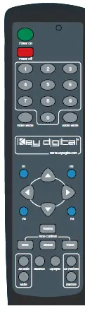
IR Extender:
You may want to use an IR extender, such as the KD-IRKIT300. Front and Rear panel sensors are available for use with the IR extender. A wired IR serial connector is also provided at the rear of the unit. Wired IR Extender KD-IRB3099 in the KD-IRKIT300 uses a 3.5mm male-to-male Mono cable. (Not Included with KD-HD4x4/6×6/8x8Lite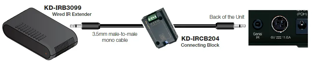
IR/Remote Control Command List
| Command | Description |
| Power On | Power On |
| Power Off | Power Off » |
| Video Output Setup Commands XX = [01-99], Y = [01-99] | |
| R1 » XX » Video Mode » Mute | Set Output XX Video Mute ON |
| R1 » Video Mode » All Mute | Set All Outputs to Video Mute ON |
| R1 » XX » Video Mode » Restore | Set Output XX to Video Mute OFF |
| R1 » Video Mode » All Restore | Set All Output to Video Mute OFF |
| R1 » XX » Video Mode » YY | Set Output XX to Video Input YY |
| R1 » Video Mode » YY | Set All Output to Video Input YY |
| System Control Setup Commands | |
| EDID Setup, XX = [01-08], YY = [01-08], ZZ = [01-12] | |
| R2 » XX » Bass » YY | Copy EDID from Output YY to Input XX |
| R2 » Bass » YY | Copy EDID from Output YY to All Inputs |
| R2 » XX » Treble » ZZ | Copy EDID from Default EDID ZZ to Input XX |
| R2 » Treble » ZZ | Copy EDID from Default EDID ZZ to All InputS |
| > DEFAULT EDID 01 : HDMI Video 1080i@60, Audio 2CH PCM Audio > DEFAULT EDID 02 : HDMI Video 1080i@60, Audio PCM,DTS/DOLBY > DEFAULT EDID 03 : HDMI Video 1080i@60, Audio PCM,DTS/DOLBY/HD > DEFAULT EDID 04 : HDMI Video 1080p@60, Audio 2CH PCM Audio > DEFAULT EDID 05 : HDMI Video 1080p@60, Audio PCM,DTS/DOLBY > DEFAULT EDID 06 : HDMI Video 1080p@60, Audio PCM,DTS/DOLBY/HD > DEFAULT EDID 07 : HDMI Video 1080p@60/3D, Audio 2CH PCM Audio > DEFAULT EDID 08 : HDMI Video 1080p@60/3D, Audio PCM,DTS/DOLBY > DEFAULT EDID 09 : HDMI Video 1080p@60/3D, Audio PCM,DTS/DOLBY/HD > DEFAULT EDID 10 : DVI Video Max. 1280×1024@60, No Audio > DEFAULT EDID 11 : DVI Video Max. 1920×1080@60, No Audio > DEFAULT EDID 12 : DVI Video Max. 1920×1200@60, No Audio | |
| System Addressing Mode | |
| R3 » R2 » R4 » X » X | Set System Address xx [xx=00-99] |
| R4 » X » X | Prefix Command for Addressing Mode xx [xx=00-99] |
RS-232 Commands
The KD-HD4x4/6×6/8x8Lite provide access to all functions when used with an RS-232 control system.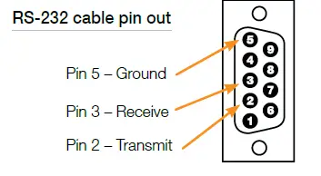
NOTE: Commands are not case sensitive. Spaces are shown for clarity; commands should not have any spaces. Every command below requires a carriage return at the end of the string for the command to be executed. If a new command is received, a prompt should be sent back
Most Common RS-232 Commands:
- H: Help – Help command. List of all RS-232 commands and Firmware version.
- STA: Status Command – Displays unit status for all internal variables such as Video Input, and EDID selected for each Input.
- PF: Power Off – Power Off command
- PN: Power ON – Power ON command
Commands
Video Switch:
- ‘SP O xx SI yy’ To switch the desired Video Input to the desired Output:
- xx = the Output number [01-04/06/08] –OR- [A] for ‘All’
- yy = the Input number [01-04/06/08] –OR- [U, D] for ‘Up’,’ Down’ respectively.
- ‘U/D’ will increase/decrease the input number from its current position.
- This command will switch Inputs to your desired Output.
- Example: To switch Output 3 to Input 1, issue the command; ‘SPO01SI03’
- Example: To incrementally switch the Input Up from its present number for Output 1, issue the command: ‘SPO01SIU’
- Example: To switch All Outputs to Input 3, issue the command: ‘SPOASI03’ EDID Copy and Default EDID Library:
- ‘SP C EDID xx H/C/D yy’: To Copy EDID to Input from HDMI Output, or from a Default Library
- xx = Input numbers [01-04/06/08] –OR- [A] for ‘All’ Inputs
- H = EDID Copy from HDMI Output
- C = EDID Copy from CAT Output
- D = Default EDID Library selection (see list below)
- yy = Output numbers [01-04/06/08] when ‘H’ variable is selected –ORDefault EDID library settings [01-12] when ‘D’ variable is selected.
- This command will either copy the EDID information from a selected Output to a specific
- Input (or All Inputs), or, write EDID information from an internal library of default EDID settings to a specific Input (or All Inputs).
- Example: To copy the EDID information from HDMI Output 2 to Input 4, issue the command: ‘SPCEDID04H02’
- Example: To write the EDID information from the built-in default EDID library using default EDID 1 to Input 2, issue the command; ‘SPCEDID02D01’
- The possible EDID settings can range from ‘01’ to ‘12’. (‘04’ is the default).
01 1080i, 2CH Audio 07 3D, 1080p 2CH Audio 02 1080i, DOLBY/DTS 5.1 08 3D, DOLBY/DTS 5.1 03 1080i, HD Audio 09 3D, HD Audio 04 1080p, 2CH Audio 10 1280×1024 DVI 05 1080p, DOLBY/DTS 5.1 11 1920×1080 DVI 06 1080p, HD Audio 12 1920×1200 DVI
Front Panel Buttons Enabled/Disabled:
- ‘SP C FB E/D’
- Where ‘E’ will Enable the front panel buttons and ‘D’ will Disable the front panel buttons.
- Example: To Disable the front panel buttons, issue the command; ‘SPCFBD’
Reset to Factory Defaults:
- ‘SP C DF xx’
- xx = [01-12] and is the default EDID library loaded during a factory reset.
- This command will return the unit to its factory default settings including a user chosen default EDID setting. (See above for a list of possible default EDID library settings available)
- Example: To reset the unit to factory default with an EDID setting of 1080i 2CH Audio, issue the command; ‘SPCDF01’
- Example: To reset the unit to factory default with an EDID setting of 3D 1080p 2CH Audio, issue the command; ‘SPCDF07’
RS-232, USB, TCP/IP Command List:
| No | Command | Description |
| 1 | Azz | Commands may require an address prefix if unit has been addressed ( zz=[00-99]) |
| 2 | H | Help |
| 3 | PHO | Help for Output Setup Commands |
| 4 | PHE | Help for EDID Setup Commands |
| 5 | PHC | Help for Control I/O Setup Commands |
| 6 | PHT | Help for Status Commands |
| 7 | PF | Power Off |
| 8 | PN | Power ON |
| System Control Setup Commands | ||
| 9 | SPC A xx | Set System Address, xx = [00-99] (00=Single) |
| 10 | SPC CM x | Set System Command Mode, x = [0-9], Default 0, Reserved for master control feature with Compass Control |
| 11 | SPC UM x | Set System User Mode, x = [0-1], Default 1. If x is 0, return message is by micro-code, and if x is 1, return is by string message. |
| 12 | SPC FB E/D/T | Front Panel Buttons Enabled/Disabled/Toggle |
| 13 | SPC BIRS z | IR Source for HD8x8, z = [1-2] (1-Wired,2-Sensor) |
| 14 | SPCDF | Set Factory Default without changing EDID |
| 15 | SPCDF zz | Set Factory Default with updated EDID zz=[01-12] (DEFAULT EDID 01-12) |
| Network Setup, xxx = [000-255], zzzz = [0001-9999] | ||
| 16 | SPC ETIPA xxx.xxx. xxx.xxx | Set Host (unit) IP Address to xxx.xxx.xxx.xxx |
| 17 | SPC ETIPM xxx. xxx.xxx.xxx | Net Mask to xxx.xxx.xxx.xxx |
| 18 | SPC ETIPR xxx.xxx. xxx.xxx | Set Router IP Address to xxx.xxx.xxx.xxx |
| 19 | SPC ETIPP zzzz | Set TCP/IP Port to zzzz |
| Video Output Setup Commands xx = [01-08,A], yy = [01-08] (A=All) | ||
| 20 | SPOxx VM E/D/T | Set Video Mute for Output xx Video Mute Enabled/Disabled/Toggle |
| 21 | SPOxx ON/OFF | Set Output ON/OFF |
| 22 | SPOxx SI yy | Set Output xx to Video Input yy |
| 23 | SPO A PT | Set All Input/Output Video to Pass-Through (Ex, Output1 = Input1, Output2 = Input2…., Output8 = Input 8) |
| 24 | SPOxx HFM A/D/H | Set Output xx Video Format: Auto: Set output video format automatically based on connected display Forced DVI: Set video format to DVI H(Bypass): Set output video format according to selected input video format. DVI in => DVI out, HDMI in => HDMI out |
| Control I/O Setup Commands xx = [01-08,A], yy = [01-08] (A=All), z = [1-6] 1 = External I/O, 2 = HDMI Input, 3= HDMI Ouput, 4 = CAT5e/6 Output, 5 = Over IP | ||
| 25 | SPI xx IR z S yy | Route IR from xx to HDMI input yy from z; xx=IR destination, yy=IR source, z=IR Origin Port Type |
| 26 | SPI xx IRR z S yy | Route IR from xx to HDMI input yy from z; xx=IR destination, yy=IR source, z=IR Origin Port Type |
| 27 | SPI xx RS z S yy | Route RS232 from xx to HDMI input yy from z; xx=RS232destination, yy=RS232 source, z=RS232 Origin Port Type |
| 28 | SPI xx RSS z S yy | Route RS232 from xx to HDMI input yy from z; xx=RS232destination, yy=RS232 source, z=RS232 Origin Port Type |
| 29 | SPOH xx IR z S yy | Route IR from xx to HDMI Output yy from z; xx=IR destination, yy=IR source, z=IR Origin Port Type |
| 30 | SPOH xx IRR z S yy | Route IR from xx to HDMI Output yy from z; xx=IR destination, yy=IR source, z=IR Origin Port Type |
| 31 | SPOH xx RS z S yy | Route RS232 from xx to HDMI Output yy from z; xx=RS232destination, yy=RS232 source, z=RS232 Origin Port Type |
| 32 | SPOH xx RSS z S yy | Route RS232 from xx to HDMI Output yy from z; xx=RS232destination, yy=RS232 source, z=RS232 Origin Port Type |
| 33 | SPOC xx IR z S yy | Route IR from xx to RJ45 Output yy from z; xx=IR destination, yy=IR source, z=IR Origin Port Type |
| 34 | SPOC xx IRR z S yy | Route IR from xx to RJ45 Output yy from z; xx=IR destination, yy=IR source, z=IR Origin Port Type |
| 35 | SPOC xx RS z S yy | Route RS232 from xx to RJ45 Output yy from z; xx=RS232destination, yy=RS232 source, z=RS232 Origin Port Type |
| 36 | SPOC xx RSS z S yy | Route RS232 from xx to RJ45 Output yy from z; xx=RS232destination, yy=RS232 source, z=RS232 Origin Port Type |
| 37 | SPE xx IR z S yy | Route IR from xx to I/O Port yy from z; xx=IR destination, yy=IR source, z=IR Origin Port Type |
| 38 | SPE xx IRR z S yy | Route IR from xx to I/O Port yy from z; xx=IR destination, yy=IR source, z=IR Origin Port Type |
| 39 | SPE xx RS z S yy | Route RS232 from xx to I/O Port yy from z; xx=RS232destination, yy=RS232 source, z=RS232 Origin Port Type |
| 40 | SPE xx RSS z S yy | Route RS232 from xx to I/O Port yy from z; xx=RS232destination, yy=RS232 source, z=RS232 Origin Port Type |
| 41 | SPC ARCxx ON/OFF | Set Output xx ARC ON/OFF |
| EDID Setup, xx = [01-08,A], yy = [01-08], zz = [01-12] | ||
| 42 | SPC EDID xx H yy | Copy EDID from HDMI Output yy to Input xx |
| 43 | SPC EDID xx C yy | Copy EDID from RJ45 Output yy to Input xx |
| 44 | SPC EDID xx D zz | Copy EDID from Default EDID zz to Input xx |
| > DEFAULT EDID 01 : HDMI Video 1080i@60, Audio 2CH PCM Audio > DEFAULT EDID 02 : HDMI Video 1080i@60, Audio PCM,DTS/DOLBY > DEFAULT EDID 03 : HDMI Video 1080i@60, Audio PCM,DTS/DOLBY/HD > DEFAULT EDID 04 : HDMI Video 1080p@60, Audio 2CH PCM Audio > DEFAULT EDID 05 : HDMI Video 1080p@60, Audio PCM,DTS/DOLBY > DEFAULT EDID 06 : HDMI Video 1080p@60, Audio PCM,DTS/DOLBY/HD > DEFAULT EDID 07 : HDMI Video 1080p@60/3D, Audio 2CH PCM Audio > DEFAULT EDID 08 : HDMI Video 1080p@60/3D, Audio PCM,DTS/DOLBY > DEFAULT EDID 09 : HDMI Video 1080p@60/3D, Audio PCM,DTS/DOLBY/HD > DEFAULT EDID 10 : DVI Video Max. 1280×1024@60, No Audio > DEFAULT EDID 11 : DVI Video Max. 1920×1080@60, No Audio > DEFAULT EDID 12 : DVI Video Max. 1920×1200@60, No Audio | ||
| Status Commands: xx = [01-08, A=all] | ||
| 45 | STA | Show Global System Status |
| 46 | STPC | Show Control System Setup Status |
| 47 | STPExx | Show Expansion I/O xx Status |
| 48 | STPIxx | Show Video Input xx Status |
| 49 | STPOxx | Show Video Output xx Status |
| 50 | STMA | Show Global System Status by Micro-Code |
| 51 | STMC | Show Control System Setup Status by Micro-Code |
| 52 | STMExx | Show Expansion I/O xx Status by Micro-Code |
| 53 | STMIxx | Show Video Input xx Status by Micro-Code |
| 54 | STMOxx | Show Video Output xx Status by Micro-Code |
Firmware Upgrade Procedure
KD-HD4x4/6×6/8x8Lite units are firmware upgradeable via USB.
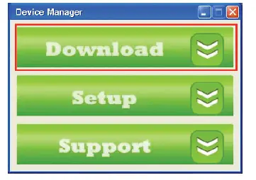
First you must download the Device Manager software from the KD-4x4Lite/KD-6x6Lite or KD-8x8Lite product pages on the Key Digital website. The software can be found under the “Downloads” section.
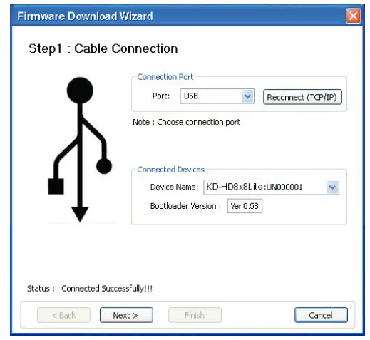
- Connect the Digital IQ unit to your PC via USB or RS-232
- Open the Device Manager software and select Download on the Home Page

- Wait for confirmation that the PC has established a connection with the Digital IQ unit

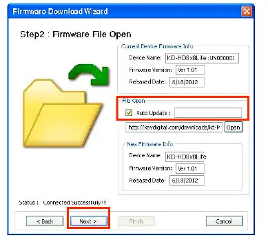
- Select Auto Update selection box, and then begin the firmware update by selecting Next

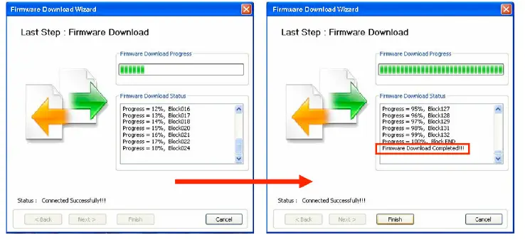
- Observe status of the firmware update through completion

- Select Finish to close
Audio Return Channel
Audio Return Channel features rely on CEC to work effectively. CEC is not enabled through the KD-HD4x4/6×6/8x8Lite matrix; therefore a CEC connection must be made elsewhere. This connection can be enabled by connecting two Champion Series™ HiFi Commercial ProS HDMI cables together with a male to male 3.5mm stereo cable from an ARC supported TV and an ARC supported AV Receiver. The audio return channel is not output via HDMI, but instead it is sent to the corresponding 3.5mm expansion port of the output to which the ARC audio is connected to.
A common 3.5mm stereo to L/R RCA Y-cable may be used to connect to your AVR, however, the audio output signal will be PCM digital and will only be carried on one of the RCA leads.
Example: An ARC compatible display is connected to output 8. The audio will be sent to 3.5mm expansion port number 8.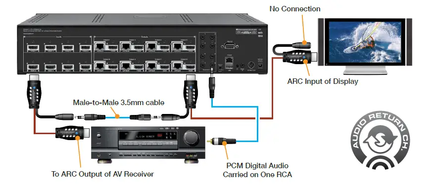
ARC Requirements:
- Display that supports ARC
- AV Receiver that supports ARC
- Champion Series™ HiFi Commercial ProS HDMI Cables
- Male to Male Stereo Cable
- 3.5mm to RCA cable
Specifications
Technical:
- Input (Each): 1 HDMI Connector, Type A, 19 Pin Female
- Output (Each): 1 HDMI Connector, Type A, 19 Pin Female; Single CAT5e/6 on RJ45 connectors
- Bandwidth: TMDS bandwidth 3.4 Gb/s
- Control: Front panel push buttons and LEDs; IR sensor front/rear; RS-232 Tx/Rx lines with full bi-directional operation
- Video/Audio Matrix Switching: Full matrix switching for HDBT/HDMI Video & Audio, DVI Video
- Deep Color Support: Supports digital video formats in Deep Color Mode up to 12 bits/color with all HDMI and HDCP technologies
- HDMI® and HDCP Licensing: Fully licensed and compatible with all HDMI and HDCP technologies
- Link: Single Link
- EDID Control: EDID information is assigned to the inputs from the internal EDID library or from a display’s internal EDID data
- Lossless Compressed Digital Audio: Dolby® TrueHD, Dolby® Digital Plus and DTS™-HD Master Audio
- DDC Signal (Data): Input DDC Signal – 5 Volts p-p (TTL)
- HDMI Video/Audio Signal: Input Video Signal – 1.2 Volts p-p
- DDC Communication: EDID and HDCP Bi-directional Transparency from Display to Source
- Wired IR: modulated IR signal input, 0-5V TTL or -10to +10V.
- Power: KD-HD4x4/6×6/8x8Lite: +6V/11.6A (70W); KD-CATHD250POHRx:+12V/6A (70W)
General:
- Regulation: CE, RoHS, WEEE
- Rack Mount:
- KD-HD6x6Lite, KD-HD8x8Lite: 2U, Full Rack Width (rack ears included)
- KD-HD4x4Lite: 1U
- Enclosure: Black Metal
- Product Dimensions:
- KD-HD6x6Lite / KD-HD8x8Lite: 17.3” x 6.6” x 3.46”
- KD-HD4x4Lite: 17.125” x 5.50” x 1.75”
- Shipping Dimensions:
- KD-HD6x6Lite / KD-HD8x8Lite: 19.9” x 13.7” x 7.8”
- KD-HD4x4Lite: 21.4” x 9” x 6.9”
- Product Weight:
- KD-HD6x6Lite / KD-HD8X8Lite: 6.6 lb.
- KD-HD4x4Lite: 5.5 lb.
- Shipping Weight:
- KD-HD8X8Lite: 16.5 lb.
- KD-HD6x6Lite: 14.3 lb.
- KD-HD4x4Lite: 12.1 lb.
Important Product Warnings:
- Connect all cables before providing power to the unit.
- Test for proper operation before securing unit behind walls or in hard to access spaces.
- If installing the unit into wall or mounting bracket into sheet-rock, provide proper screw support with bolts or sheet-rock anchors.
Safety Instructions
Please be sure to follow these instructions for safe operation of your unit.
- Read and follow all instructions.
- Heed all warnings.
- Do not use this device near water.
- Clean only with dry cloth.
- Install in accordance with the manufacturer’s instructions.
- Do not install near any heat sources such as radiators, heat registers, stoves, or other apparatus (including amplifiers) that produce heat.
- Only use attachments/accessories specified by the manufacturer.
- Refer all servicing to qualified service personnel. Servicing is required when the device has been damaged in any way including:
- Damage to the power supply or power plug
- Exposure to rain or moisture
Power Supply Use:
You MUST use the Power Supply provided with your unit or you VOID the Key Digital® Warranty and risk damage to your unit and associated equipment
How to Contact Key Digital® System Design Group (SDG)
For system design questions please contact us at:
Phone: 914-667-9700
E-mail: [email protected]
Technical Support
For technical questions about using Key Digital® products, please contact us at:
Phone: 914-667-9700
E-mail: [email protected]
Repairs and Warranty Service
Should your product require warranty service or repair, please obtain a Key Digital® Return Material
Authorization (RMA) number by contacting us at:
- Phone: 914-667-9700
- E-mail: [email protected]
Feedback
Please email any comments/questions about the manual to:
E-mail: [email protected]
Warranty Information
All Key Digital® products are built to high manufacturing standards and should provide years of trouble-free operation. They are backed by a limited lifetime parts and labor warranty.


