velleman K4003 2 X 30W Stereo Amplifier User Manual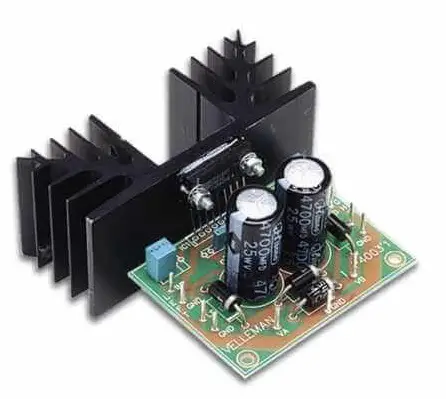
Features & Specifications
Features:
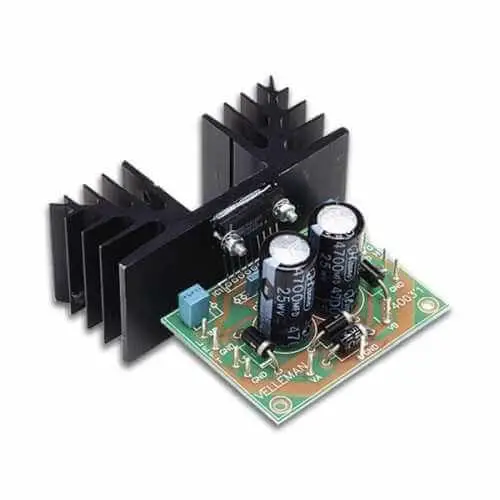
This small amplifier is constructed with the TDA2616 IC, with a maximum supply capability of 2 x 15Wrms (4ohm) of 2 x 10Wrms (8ohm). The IC is thermally and short-circuit protected. Additional rectifier and smoothing filter are unnecessary, as alternating current can be directly connected to the unit.
Specifications :
- Music power output: 2 x 30W / 4ohm
- RMS output: 2 x 15Wrms / 4ohm or 2 x 10Wrms / 8ohm
- Total harmonic distortion: 0.07% (1W / 1kHz)
- Channel separation: 70dB
- Frequency response: 7Hz to 60kHz (-3dB)
- Signal-to-noise ratio: 98dB (A weighted)
- Input sensitivity: 300mV / 150Kohm
- Transient suppression on/off switch
- Overload and short-circuit protection: max. 1h
- Supply voltage: 2 x 12Vac / 2A (50W transfo recommended)
- Dimensions: 70 x 50mm
- Recommended transformer: 212048 or 8012
Assembly (Skipping this can lead to troubles
Ok, so we have your attention. These hints will help you to make this project successful. Read them carefully.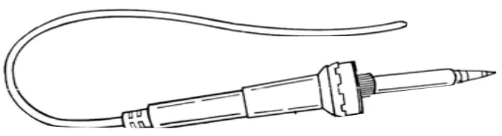
Make sure you have the right tools
- A good quality soldering iron (25-40W) with a small tip.
- Wipe it often on a wet sponge or cloth, to keep it clean; then apply solder to the tip, to give it a wet look. This is called ‘thinning’ and will protect the tip, and enables you to make good connections. When solder rolls off the tip, it needs cleaning.
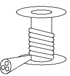
- Thin raisin-core solder. Do not use any flux or grease.
- A diagonal cutter to trim excess wires. To avoid injury when cutting excess leads, hold the lead so they cannot fly towards the eyes.
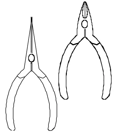
- Needle nose pliers, for bending leads, or to hold components in place.
- Small blade and Phillips screwdrivers. A basic range is fine
![]() For some projects, a basic multi-meter is required, or might be handy
For some projects, a basic multi-meter is required, or might be handy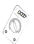
Assembly Hints
- Make sure the skill level matches your experience, to avoid disappointments.
- Follow the instructions carefully. Read and understand the entire step before you perform each operation.
- Perform the assembly in the correct order as stated in this manual
- Position all parts on the PCB (Printed Circuit Board) as shown on the drawings.
- Values on the circuit diagram are subject to changes.
- Values in this assembly guide are correct*
- Use the check-boxes to mark your progress.
- Please read the included information on safety and customer service
* Typographical inaccuracies excluded. Always look for possible last minute manual updates, indicated as ‘NOTE’ on a separate leaflet.
Soldering Hint
- Mount the component against the PCB surface and carefully solder the leads
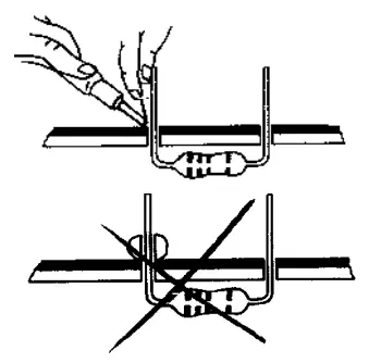
- Make sure the solder joints are cone-shaped and shiny
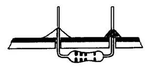
- Trim excess leads as close as possible to the solder joint
REMOVE THEM FROM THE TAPE ONE AT A TIME !
DO NOT BLINDLY FOLLOW THE ORDER OF THE COMPONENTS ONTO THE TAPE. ALWAYS CHECK THEIR VALUE ON THE PARTS LIST!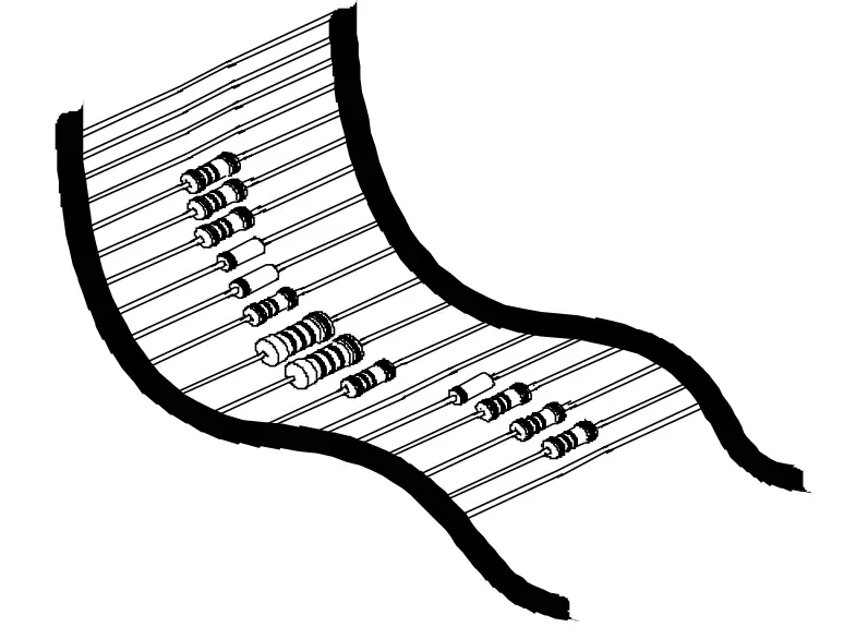
Construction
- Resistors
R1 : 8,2 (8 – 2 – B – B)
R2 : 8,2 (8 – 2 – B – B)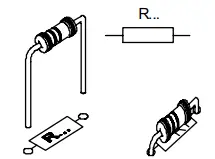
- Diodes. Watch the polarity
D1 : 1N5404
D2 : 1N5404
D3 : 1N5404
D4 : 1N5404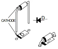
- Capacitors.
C1 : 22nF (223)
C2 : 22nF (223)
C3 : 100nF (104)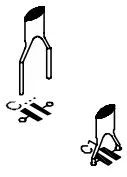
- PCB tabs
GND: Left
IN: Right
GND
LS (2x) : LS
GND (2x)
VA
ND : Mains
VB - Capacitors.
C4 : 1µF
C5 : 1µF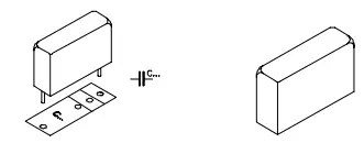
- Electrolytic Capacitors. Watch the polarity
C6 : 2200µF
C7 : 2200µF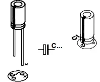
- IC
IC1 : TDA2616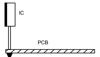
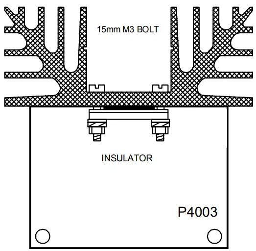
Mount the IC with the metal back pointing at the edge of the circuitboard. Mount it sufficiently high, so that the pins do NOT need to be pruned. Then mount the IC against the heatsink, as indicated in the diagram 1.0. The insulation (covered on both sides with some optional heat conductive paste, ordernr.: therm20) mica must be inserted between the IC and the heatsink.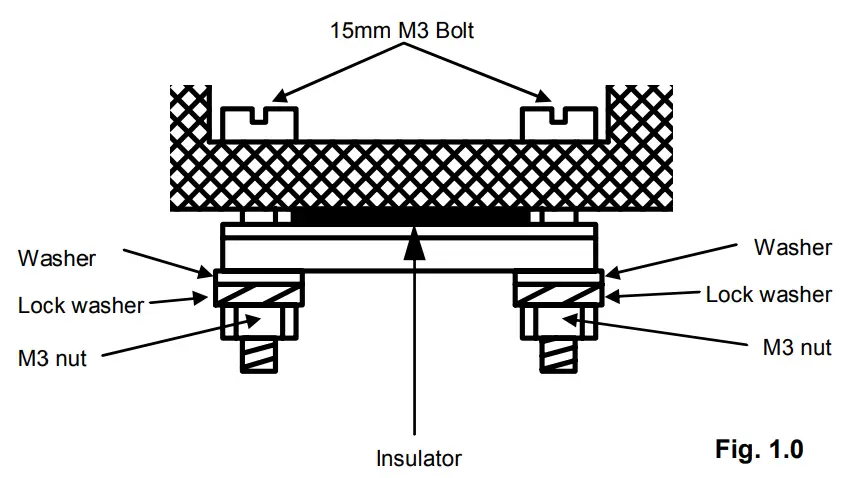
- Connection
Make the connections as indicated in figure 2.0 & fig 3.0. Watch the polarity of the loudspeakers. If a ring-core transformer is used, it is possible that the OV (GND) connection consists of two leads. Finish all connections before switching on the power.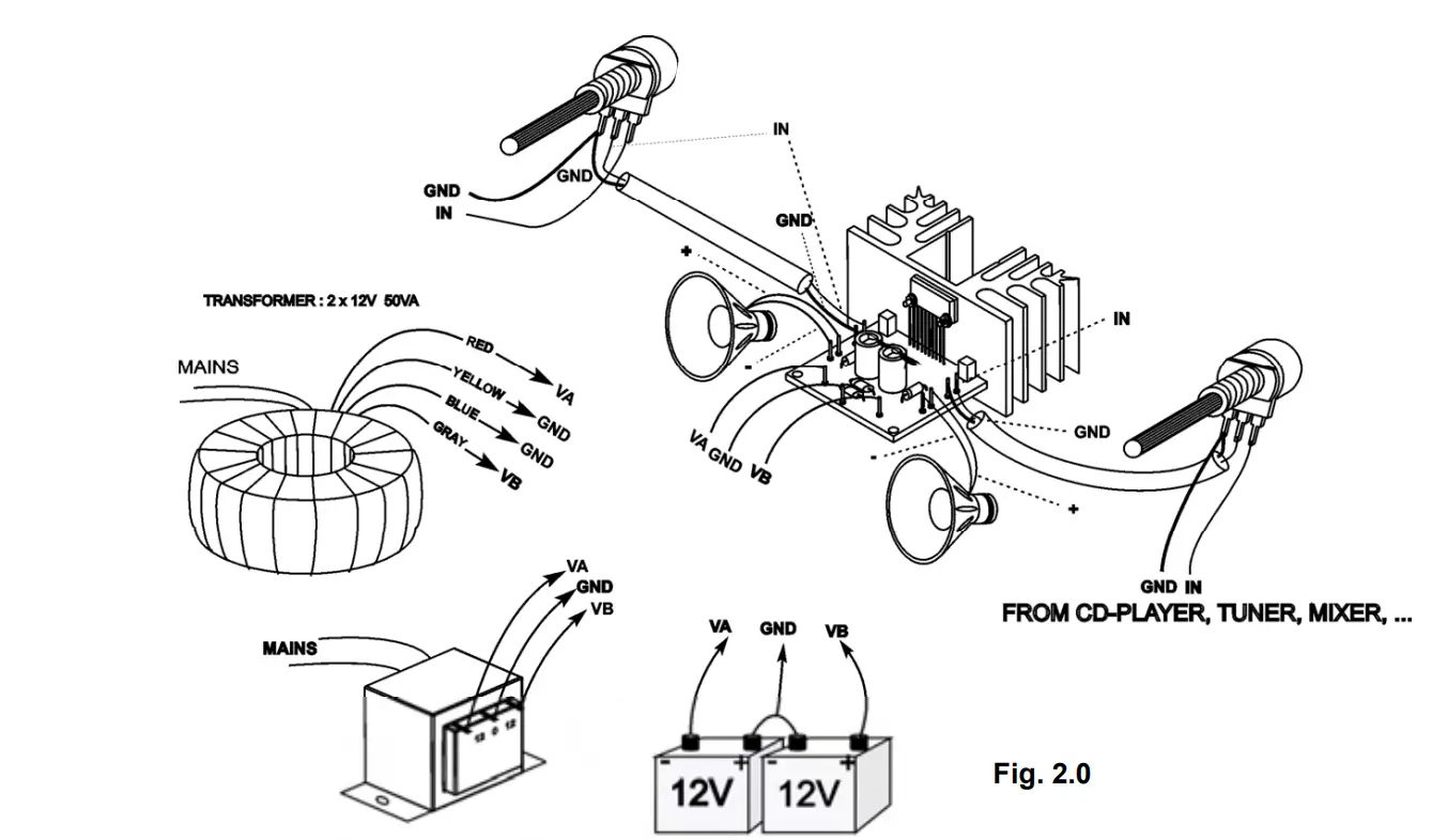
HOW TO CONNECT A VOLUME CONTROL HOE EEN VOLUMEREGELING AANSLUITEN OOMMENT ER ANCHER UN REGLAGE VOLUME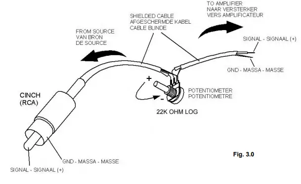
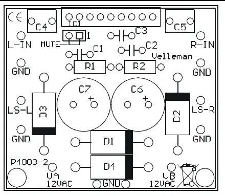
- PCB layout
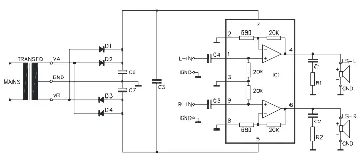
- Diagram

Modifications and typographical errors reserved
© Velleman nv.
H4003IP – 2004 – ED1 (rev.1)
VELLEMAN NV Legen Heirweg 33, 9890 Gavere Belgium – Europe


