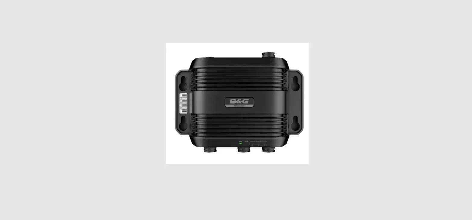
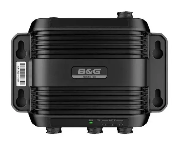
B G Nemesis Hub Combine Two OR More Nemesis 9 Or 12 Sailing Displays
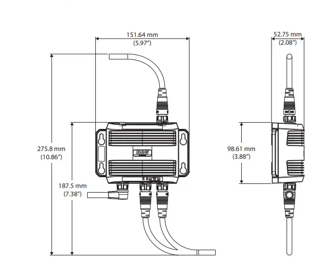
Dimensional drawing
Technical specification
| Environmental | |
| Storage temperature | -15°C to +55°C (5°F to 131°F) |
| Operating temperature | -20°C to +60°C (4°F to 140°F) |
| Waterproof rating | IPX 6 and 7 |
| Electrical | |
| Power supply | 12/24 V DC |
| Operating voltage | 12/24 V DC (10 – 31.2 V DC min – max) |
| Power consumption – Max | 2 W + power distributed to connected displays. |
| Fuse rating | 6 A |
| Physical | |
| Weight (box only) | 240g (0.44 lbs) |
| Interface/Connectivity | |
| Ethernet/Power | 1x 8-pin connector |
| Display | 3x 8-pin Ethernet connectors |
| Ground | 1x M4 Grounding |
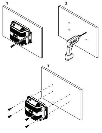
Mounting
Parts included
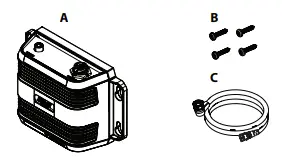
A. Ethernet switch
B. Fastening set
C. Display connection cable
D. Blanking caps (not shown in the illustration)
Accessories (sold separately)
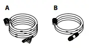
A. Power and Ethernet cable
B. Display connector cable
Compliance Statement
Declarations
The relevant Declaration of Conformity is available on the following websites:
Europe
Navico declares under our sole responsibility that the product conforms with the requirements of:
- CE under EMC Directive 2014/30/EU
United States of America
Note: The user is cautioned that any changes or modifications not expressly approved by the party responsible for compliance could void the user’s authority to operate the equipment.
Australia and New Zealand
Navico declares under our sole responsibility that the product conforms with the requirements of:
- level 2 devices of the Radiocommunications (Electromagnetic Compatibility) Standard 2017
Trademarks
®Reg. U.S. Pat. & Tm. Off, and ™ common law marks. Visit www.navico.com/intellectual-property to review the global trademark rights and accreditations for Navico Holding AS and other entities.
Ethernet and power wiring
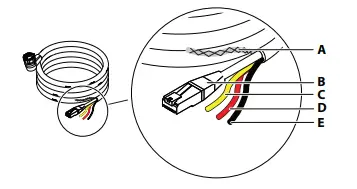
A. Shield
B. Ethernet connector (RJ45)
C. Not used, yellow
D. +12/24 V DC, red
E. DC negative, black
Power
The unit is designed to be powered by a 12 or 24 V DC system. It is protected against reverse polarity, under voltage, and over-voltage (for a limited duration). A fuse or circuit breaker should be fitted to the positive supply. For recommended fuse rating refer to the technical specifications. The shield (A) can in most cases be insulated from all other wires. If interference is encountered from other onboard electronics, the shield can be connected to a vessel hull ground to help reduce any interference, but it is not generally required. The yellow wire (B) in the power cable is not to be used and should be insulated from all other wires.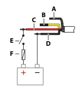
A. Shield
B. Not used, yellow
C. +12/24 V DC, red
D. DC negative, black
E. Switch
F. Fuse
The unit will turn on when power is applied.
Ethernet
Connect the Ethernet connector to your vessel’s B&G CPU Ethernet network for the transfer of data to the displays. No special setup is required for establishing an Ethernet network.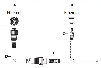
A. Ethernet switch with a 5-pin Ethernet socket
B. B&G CPU or Ethernet switch with an RJ45 Ethernet socket
C. Ethernet cable plug (RJ45)
D. Ethernet adapter cable (RJ45 to 5-pin), optional
Connectors overview
Bottom connectors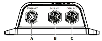
Top connectors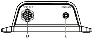
A. Ethernet – Power and Ethernet connection
B. Display connector 1
C. Display connector 2
D. Display connector 3
E. Ground, M4
Grounding
It is recommended to ground the unit. 1.5 mm2 (16 AWG) wire.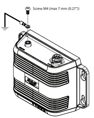
Display wiring
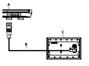
A. Ethernet switch, display port 1-3
B. Display power and Ethernet cable
C. Display
LED indicators
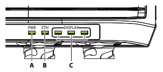
A. Power (PWR) The power indicator is lit when the unit is powered.
B. Ethernet (ETH) The Ethernet indicator blinks while data is transferred between the hub and the vessel’s Ethernet network.
C. Display 1-3 The display indicators blink while data is transferred between the hub and the connected display.


