![]()
![]() Hardware Quick Reference
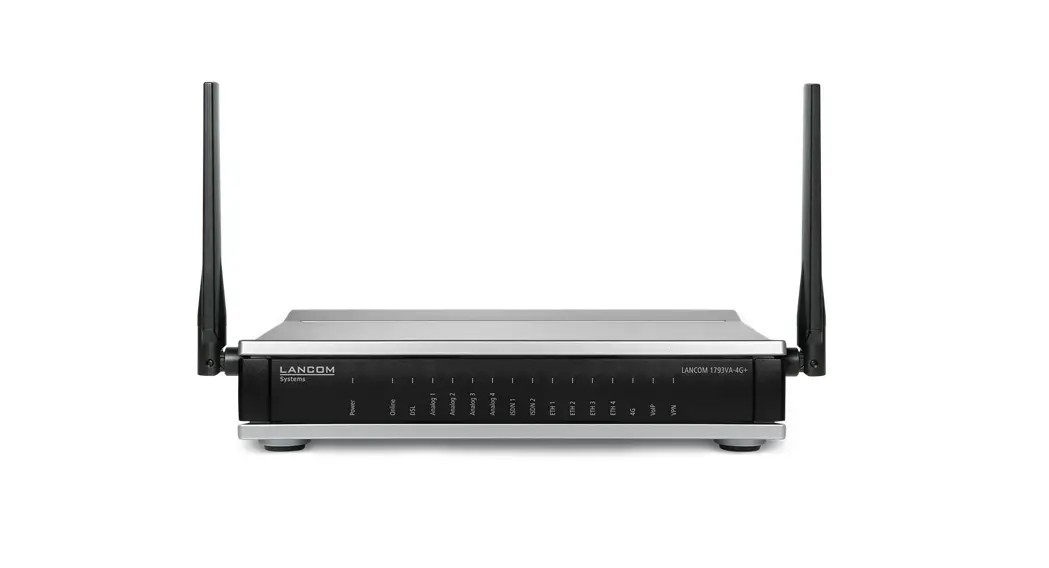
Hardware Quick Reference
LANCOME 1793VAW
1793VAW Telephony and Wi-Fi at Supervectoring Connections
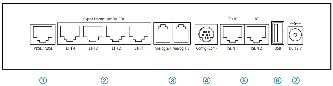
- VDSL / ADSL interface
Use the supplied DSL cable for the IP-based line to connect the VDSL interface and the provider’s telephone socket. For more information, please contact your Internet
service provider.
- Ethernet interfaces
Use an Ethernet cable to connect one of the interfaces ETH 1 to ETH 4 to your PC or a LAN switch.
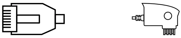
- Analog interfaces
Connect analog terminal devices to the analog interfaces either directly via RJ11, or with the help of the enclosed TAE adapters.
Further adapters are optionally available.
- Configuration interface
Use a serial configuration cable to connect the serial interface (COM) to the serial interface of the device you want to use for configuring / monitoring (separately available).
- ISDN interfaces
ISDN 1:
Internal (NT) or external (TE) ISDN bus.
This feature is controlled by LCOS.
ISDN 2:
Internal (NT) ISDN bus.
A 100-Ohm resistor for line termination is switchable in LCOS.
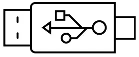
- USB interface
You can use the USB interface to connect a USB printer or a USB memory stick.
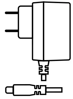
- Power
After connecting the cable to the device, turn the bayonet connector 90° clockwise until it clicks into place.
Use only the supplied power adapter.
Before initial startup, please make sure to take notice of the information regarding the intended use in the enclosed installation guide!
Operate the device only with a professionally installed power supply at a nearby power socket that is freely accessible at all times.
![]() Please observe the following when setting up the device
Please observe the following when setting up the device
→The power plug of the device must be freely accessible.
→ For devices to be operated on the desktop, please attach the adhesive rubber footpads
→Do not rest any objects on top of the device
→Keep all ventilation slots on the side of the device clear of obstruction
→In case of wall mounting, use the drilling template as supplied
→Rack installation with the optional LANCOM Rack Mount (separately available)
Mounting & connecting
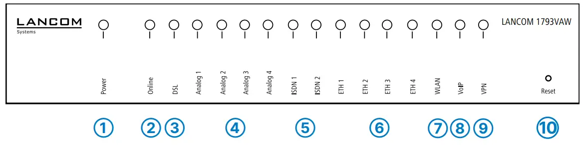
| Power | |
| Off | Device switched off |
| Green, permanently* | Device operational, resp. the device paired/ claimed and LANCOM Management Cloud (LMC) accessible |
| Red / green blinking | Configuration password not set. Without a configuration password, the configuration data in the device is unprotected. |
| Red blinking | Charge or time limit reached |
| 1x green inverse blinking* | Connection to the LMC active, pairing OK, the device not claimed |
| 2x green inverse blinking* | Pairing error, resp. LMC activation code not available |
| 3x green inverse blinking* | LMC is not accessible, resp. communication error |
| Online | |
| Off | WAN connection inactive |
| Green, blinking | WAN connection is established (e.g. PPP negotiation) |
| Green, permanently | WAN connection active |
| Red, permanently | WAN connection error |
| DSL | |
| Off | Interface deactivated |
| Green, permanently | DSL connection active |
| Green, flickering | DSL data transfer |
| Red, flickering | DSL transfer error |
| Red/orange, blinking | DSL hardware error |
| Orange, blinking | DSL training |
| Orange, permanently | DSL sync |
| Green, blinking | DSL connecting |
| Analog 1, 2, 3, 4 | |
| Off | Interface deactivated |
| Green, permanently | Interface activated |
| Orange, blinking | Incoming call |
| Green, blinking | Connection active |
| ISDN 1, 2 | |
| Off | Interface deactivated |
| Green, permanently | D-channel active |
| Green, flickering | ISDN data transfer |
| Red, flickering | ISDN transfer error |
| Red/orange, blinking | ISDN hardware error |
| ETH 1, 2, 3, 4 | |
| Off | No networking device attached |
| Green, permanently | Connection to the network device operational, no data traffic |
| Green, flickering | Data transmission |
| WLAN | |
| Off | No Wi-Fi network is defined or the Wi-Fi module is deactivated. The Wi-Fi module is not transmitting beacons. |
| Green, permanently | At least one Wi-Fi network is defined and a Wi-Fi module activated. The Wi-Fi module is transmitting beacons. |
| Green, blinking | DFS scanning or other scan procedure |
| Red, blinking | Hardware error in Wi-Fi module |
| VoIP | |
| Off | No SIP accounts are defined or VCM is off |
| Green, permanently | All defined and active SIP accounts (outgoing) were successfully registered |
| Red, permanently | Not all defined and active SIP accounts are registered (possibly still in process) |
| Red or green, inverse flashing | Number of currently used lines (connecting or connected) |
| VPN | |
| Off | VPN connection inactive |
| Green, permanently | VPN connection active |
| Green, flashing | VPN connecting |
| Reset | |
| Reset button | Operated e.g. with a paper clip short press: Restart the device long press: Reset the device |
Hardware
| Power supply | 12 V DC, external power adapter (230 V); bayonet connector to secure against disconnection |
| Power consumption | Max. 17 W |
| Environment | Temperature range 0–40 °C; humidity 0–95 %, non-condensing |
| Housing | Robust synthetic housing, rear connectors, ready for wall mounting, Kensington lock; measure 210 x 45 x 140 mm (W x H x D) |
| Number of fans | 1 quiet fan |
Interfaces
| WAN: VDSL2 | VDSL2 as per ITU G.993.2; profiles 8a, 8b, 8c, 8d, 12a, 12b, 17a, 35b VDSL Supervectoring as per ITU G.993.2 (Annex Q) VDSL2 vectoring as per ITU G.993.5 (G.Vector) Compatible with VDSL2 and U-R2 from Deutsche Telekom (1TR112) ADSL2+ over ISDN as per ITU G.992.5 Annex B/J with DPBO, ITU G.992.3, and ITU G.992.1 ADSL2+ over POTS as per ITU G.992.5 Annex A/M with DPBO, ITU G.992.3, and ITU.G.992.1 Supports just one virtual connection at a time in ATM (VPI-VCI pair) |
| Wi-Fi | Frequency band: 2400-2483.5 MHz (ISM) or 5150-5825 MHz (restrictions vary between countries) Radio channels 2.4 GHz: Up to 13 channels, max. 3 non-overlapping (2.4-GHz band) Radio channels 5 GHz: Up to 26 non-overlapping channels (channels available vary according to country regulations; DFS for automatic dynamic channel selection required) |
| ETH | 4 individual ports, 10 / 100 / 1000 Mbps Gigabit Ethernet, by default set to switch mode. Up to 3 ports can be operated as additional WAN ports. Ethernet ports can be electrically disabled in the LCOS configuration. |
| USB | USB 2.0 hi-speed host port for connecting USB printers (USB print server), serial devices (COM-port server) or USB drives (FAT file system) |
| ISDN 1 / ISDN 2 | ISDN 1: Internal (NT) or external (TE) ISDN bus. This feature is controlled by LCOS. According to the settings, connect an ISDN cable either to the NTBA or the ISDN terminal device. ISDN 2: Internal (NT) ISDN bus. Use an ISDN cable to connect the ISDN device to the ISDN interface. |
| Analog 1 / Analog 3 Analog 2 / Analog 4 | Use the cable of your analog devices to connect them with the analog interfaces. If necessary use the adapters from the LANCOM Analog Adapter Set. |
| Config (Com) / V.24 | Serial configuration interface/COM-port (8-pin mini-DIN): 9,600 – 115,200 baud, suitable for optional connection of analog/GPRS modems. Supports internal COM-port server and provides transparent asynchronous serial-data transfer via TCP. |
WAN protocols
| VDSL, ADSL, Ethernet | PPPoE, PPPoA, IPoA, Multi-PPPoE, ML-PPP, PPTP (PAC or PNS) and IPoE (with or without DHCP), RIP-1, RIP-2, VLAN |
| ISDN | DSS1 (Euro-ISDN), PPP, X75, HDLC, ML-PPP, V.110/GSM/HSCSD |
Package content
| Cable | 1 DSL cable for an IP-based line, 4.25 m |
| Adapters | 2 TAE adapters (RJ11 – TAE) |
| Power adapter | External power supply adapter (230 V), 12 V / 2 A DC/S; barrel/bayonet (EU), LANCOM item no. 111303 (not for WW devices) |
*) The additional power LED statuses are displayed in a 5-second rotation if the device is configured to be managed by the LANCOM Management Cloud.
This product contains separate open-source software components which are subject to their own licenses, in particular the General Public License (GPL). The license information for the device firmware (LCOS) is available on the device‘s WEBconfig interface under “Extras > License information“. If the respective license demands, the source files for the corresponding software components will be made available on a download server upon request.
Hereby, LANCOM Systems GmbH | Adenauerstrasse 20/B2 | D-52146 Wuerselen, declares that this device is in compliance with Directives 2014/30/EU, 2014/53/EU, 2014/35/EU, 2011/65/EU, and Regulation (EC) No. 1907/2006. The full text of the EU Declaration of Conformity is available at the following Internet address: www.lancom-systems.com/doc


