
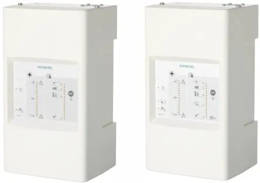
SIEMENS FDA241 ASD Aspirating Smoke Detector
Siemens aspirating smoke detector (ASD) for the addressed FDnet/C-NET de-tector line or for standalone operation
- Patented technology
- Early detection of a wider spectrum of particle sizes in the air
- Configuration using the USB interface or the control panel via FDCC221S (op-tional)
- ‘ASD Asyst-Tool’ software to assist with pipe configuration
- Unique dust-resistant detection chamber
- Intuitive front indicator for airflow and smoke value
- Access to service functions
- Different event protocols
- Offline/online configuration supported
- Cleaning function (FDA241)
- 4…20 mA output
Properties
- Extended optical detection thanks to dual wavelengths (blue and infrared): The aspirat-ing smoke detectors FDA241 and FDA221 use dual-wavelength technology to trigger an alarm at the earliest possible moment. They are designed to protect small and medium-sized business-critical environments for monitoring areas of up to 800 m2 (FDA241) or 500 m2 (FDA221). The detectors continually suck in air through a pipe system via their aspirating holes. The air is fed into a uniquely designed detection chamber, in which tiny smoke particles are detected by scattered light.
- Lower mounting and service costs: The aspirating smoke detectors FDA241 and FDA221 can be used on an FDnet/C-NET detector line. For this purpose, communication transponder FDCC221S is required.
- Configuration using the USB interface or the control panel via FDCC221S (optional): All detector configurations, maintenance work, and alarm and fault management processes can be carried out at a central location – the fire control panel. This ensures better con-trol while also reducing the costs of the overall solution.
- Out-of-the-box’ mounting and commissioning: Installation is simple thanks to combined functions for normalizing smoke values and airflow, as well as appropriate presettings for alarm and fault thresholds.
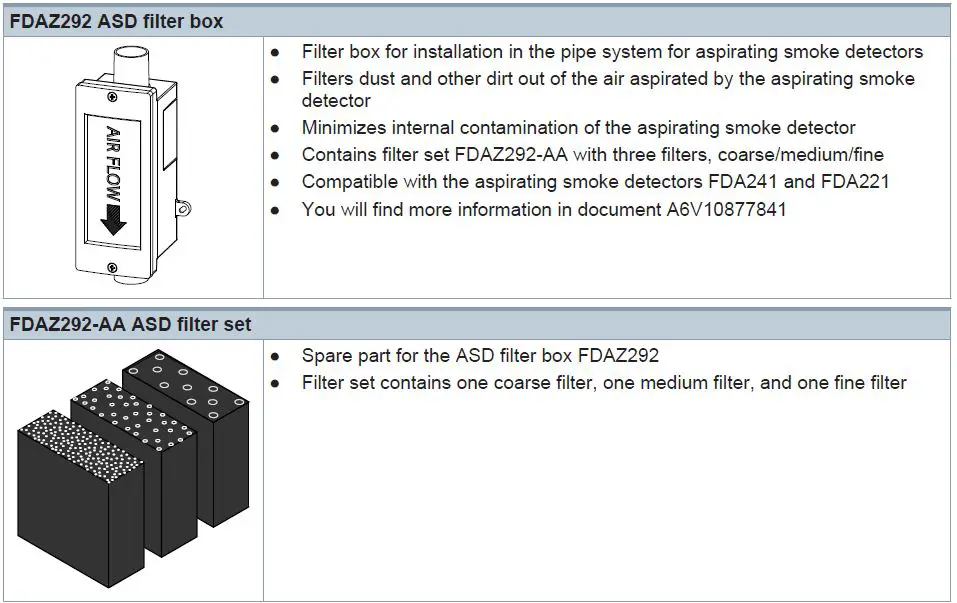
- ASD filter box FDAZ292 available as an accessory: Dust and other dirt is filtered out of the aspirated air and does not get into the aspirating smoke detector. The filters in the ASD filter box are easy to replace.
Use
Aspirating smoke detectors are used for early detection of smoke-generating fires in rooms and equipment. They are especially suited to applications in which point detectors are pushed to their limits, cannot be used or can only be used with restrictions.
The aspirating smoke detector continually takes air from the monitored room using a connec-ted pipe system with defined aspirating holes. The air is supplied to the detection chamber and is analyzed for smoke particles using the detector installed there. The sensitivity of the detector can be adjusted.
The position and size of the aspirating holes is calculated using the ‘FXS2056 ASD Asyst Tool V2’ software. The calculation ensures that the air passes from the aspirating hole to the detector in the time specified and with the required calculated sensitivity.
The ‘FXS2056 ASD Asyst Tool V2’ software replaces the ‘FXS2055 ASD Asyst Tool’ soft-ware.
Examples of application
- Cavities such as false ceilings or false floors
- Clean rooms
- Rooms the height of which is greater than that permitted for point detectors
- Rooms with electromagnetic fields which influence the function of point detectors
- Large rooms up to 800 m²
- Separate monitoring of control cabinets and electronics cabinets
- Data centers
- Telecommunication centers
- Mounting lines
- Cable tunnels
- Conveyor belts
Applications with a filter box
- Rooms with polluted air, in which the pollution has impaired the performance of optical point detectors
- Mounting lines
- Recycling facilities
- Cement factories
- Mining industry
- Subway stations
- Agricultural operations
- All other applications with visible dust load
Functions
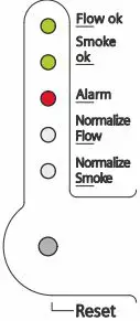
Indication
The display contains clear, comprehensible bar graphs for smoke and airflow, as well as an alarm indicator, an error indicator, and a dust indicator (FDA241).
When the housing cover is open, the operator has access to the ‘Reset’, ‘Normalize Smoke’, and ‘Normalize Flow’ functions, as well as the mini USB connector.
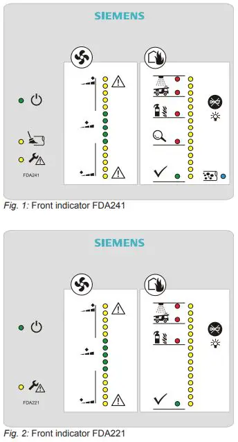
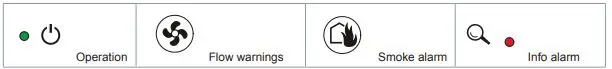
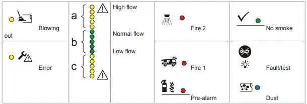
Legend for the response indicators
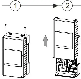
Opening the detector
CAUTION
Damage to the connection cable
In order to prevent damage to the connection cable when positioning the housing cover, make sure that the connection cable has been routed correctly.
The service area for the detector can be accessed in two ways.
- Partial access:
- Remove the two screws on the top of the detector.
- Slide the housing cover up until you hear it snap into place.
- Full access:
- Remove the two screws on the top of the detector.
- Slide the housing cover up until you hear it snap into place.
- Pull the housing cover out slightly at the sides and lift it up.
- Remove the housing cover.

Service LED indicators and buttons
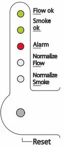
- Flow OK
As soon as the selftest for normal operation has been completed successfully, the ‘Flow OK’ LED starts to flash. - Smoke OK
As soon as the selftest for normal operation has been completed successfully, the
‘Smoke OK’ LED starts to flash. - Alarm
In the event of a smoke alarm, the ‘Alarm’ LED starts to flash. - Normalization of the airflow
To determine the nominal airflow of the detector, perform this function during commissioning. The nominal value established during normalization of the airflow forms the setpoint value for monitoring the airflow during normal operation.
To perform this function, use a thin object (such as a paper clip or a watchmaker’s screw-driver) to press the button in the opening.
Once you have finished with this function, press the button in the opening again.
The smoke detector uses standard values for monitoring during normalization. - Normalization of the smoke density
- To determine the nominal air quality in relation to the smoke density, perform this function during commissioning. \
- The nominal value established during normalization forms the set-point value for monitoring the smoke density during normal operation.
- To perform this function, use a thin object (such as a paper clip or a watchmaker’s screw-driver) to press the button in the opening.
- Once you have finished with this function, press the button in the opening again.
- The smoke detector uses standard values for monitoring during normalization.
The detector provides information about the current normalization process via FDnet/C-NET (no distinction is made between smoke and airflow).
- Reset button
Use the reset button to reset all of the detector’s status indicators. These indicators can refer to fire alarms or airflow events. Resetting the fire alarm also resets the associated relay.
If the detector is operated on the FDnet/C-NET, the alarms and the associated relays are not reset. - USB connection
You can use a mini USB cable to connect the detector to a Windows PC. To set up the de-tector, use the configuration tool ‘FXS2051 ASD Configuration Tool’. - Test function LED
Hold the ‘Buzzer silence’ button down for 5 seconds. The LEDs on the display are tested with 3 different brightness settings.
If the aspirating smoke detector is to be operated on the FDnet/C-NET, the communication interface FDCC221S (S24218-A201-A2) must be ordered separately.
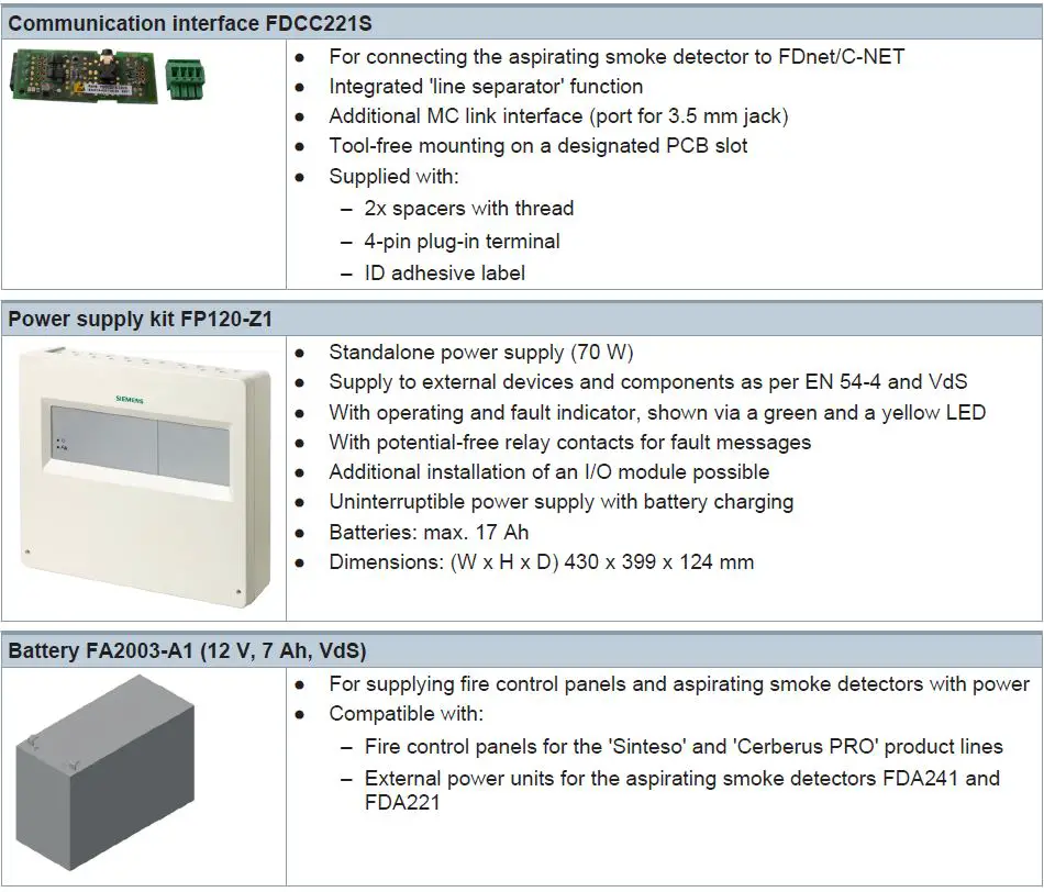
Accessories
Type Overview
| Type | Designation | Order number | Weight [kg] |
| FDA241 | Aspirating smoke detector (8H) | S54333-F17-A1 | 1.495 |
| FDA221 | Aspirating smoke detector (5S) | S54333-F15-A1 | 1.495 |
| Accessories | |||
| FDCC221S | Communications interface | S24218-A201-A2 | 0.019 |
| FP120-Z1 | Power supply kit A (70 W) | S54400-S122-A1 | 3.920 |
| FA2003-A1 | Battery (12 V, 7 Ah, VdS) | A5Q00019353 | 2.450 |
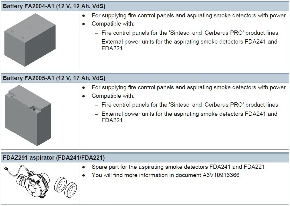
| FA2004-A1 | Battery (12 V, 12 Ah, VdS) | A5Q00019354 | 3.930 |
| FA2005-A1 | Battery (12 V, 17 Ah, VdS) | A5Q00019677 | 5.640 |
| FDAZ292 | ASD filter box | S54333-C92-A1 | 0.220 |
| Spare parts | |||
| FDAZ292-AA | ASD filter set | S54333-S91-A1 | 0.009 |
| FDAZ291 | Aspirator (FDA241/FDA221) | S54333-G1-A1 | 0.106 |
Product documentation
| Document ID | Title |
| A6V10334410 | Technical manual Aspirating smoke detector FDA241, FDA221 |
| A6V10393194 | Technical manual Power supply kit A 70 W FP120-Z1 |
| A6V10345654 | Installation, Mounting Aspirating smoke detector FDA241, FDA221 |
| A6V10340094 | User Manual ‘ASD Asyst Tool FXS2055’ |
| A6V10728226 | User Manual ‘ASD Asyst Tool V2 FXS2056’ |
| A6V10334435 | Planning, Installation ASD Pipe system |
| A6V10332759 | Installation, Operation Manual, Configuration ‘ASD Configuration Tool FXS2051’ |
| A6V10877841 | Installation ASD Filterbox FDAZ292 |
| A6V10916591 | Installation Aspirator (FDA241/FDA221) FDAZ291 |
Related documents such as environmental declarations, CE declarations, etc., can be down- loaded at the following Internet address: http://siemens.com/bt/download
Notes
Disposal
The device is considered an electronic device for disposal in accordance with the European Guidelines and may not be disposed of as domestic garbage.
- Dispose of the device through channels provided for this purpose.
- Comply with all local and currently applicable laws and regulations.
Technical data
| FDA241 | FDA221 | |
| Operating voltage | DC 19.5…30 V | |
| Operating current at DC 24 V | 150 mA (nominal), 250 mA (during alarm) | |
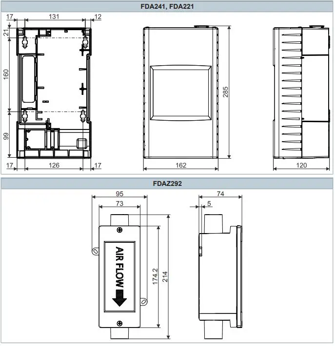
| Dimensions (W x H x D) | 162 x 285 x 120 mm | |
| Protection category | IP30 | |
| Installation position | Vertically upward, vertically downward | |
| Sound power level LWA [dBA]: 1) | – | |
| At suction speed – High – Medium – Low | 37 33 30 | 33 30 26 |
| Operating temperature | -20…+60 °C | |
| Air humidity | 5…95 % (no moisture condensation) | |
| Dust indicator | Yes | – |
| Maximum pipe length – Single line – Branched lines | 60 m 2x 60 m | 30 m 2x 25 m |
| Options for aspirating holes | Prefabricated option or the maximum pipe length must correspond to the calculation made using the software ‘FXS2056 ASD Asyst Tool V2’ | |
| Air intake/exhaust pipe | Metric: 25 mm outer diameter (OD) | |
| Monitoring area (dependent on local provisions and standards) | Up to 800 m² | Up to 500 m² |
| System compatibility | Compatible with all Siemens FC20/FC720 (FS20/FS720 systems) | |
| Relay alarm outputs Can be selected with/without self- retention Nominal current 2.0 A at DC 30 V. Contact: NO/NC | 4 | 3 |
| Fault relay | 1 | 1 |
| Cable inlet | 10 cm x 2.5 cm on the rear or from above | |
| Terminal configuration | Screw terminals | |
| Conductor cross section | 0.2…2.5 mm2 (AWG 12– 30) | |
| Other interfaces | Power supply, 4…20 mA | |
| Alarm threshold for parameter sets: | ||
| Fire 1 | 10 sets 0.05…2.0 %/m obs | 5 sets 0.20…2.0 %/m obs |
| Fire 2 | 10 sets 2.0…20 %/m obs | 5 sets 6.0…20 %/m obs |
| Alarm delay, can be set individually | 0…300 seconds: default value 0 seconds smoke density and 15 seconds flow | |
| Indication | ● 4x alarm status indicators (FDA241) ● 3x alarm status indicators (FDA221) ● Faults ● Blowing out (FDA241) ● Dust (FDA241) ● Smoke density and flow indicator | |
| FDA241 | FDA221 | |
| Service area | ● ‘Status OK’ LED ● USB ● Settings for reset functions ● Settings for smoke density and airflow | |
| Event log | Non-volatile event memory with time and date stamp for: smoke density, airflow, detector status, and faults | |
| Event memory entries | 20000 | 8000 |
| Modification memory entries | 20000 | 8000 |
| Normalization of smoke value and airflow | ● Setting of threshold values for smoke alarms and faults ● User setting for normalization of smoke density and airflow ● Preset values are retained during the normalization period | |
| Warranty period | 2 years | |
| Approvals ● VdS | FDA241 G213050 | FDA221 G213050 |
1 A-weighted sound power level in [dB] as per DIN EN ISO 3744-2009, measured with a pipe piece at the air inlet and at the air outlet
Dimensional drawings
Issued by
Siemens Switzerland Ltd
Smart Infrastructure
Global Headquarters
Theilerstrasse 1a
CH-6300 Zug
+41 58 724 2424
www.siemens.com/buildingtechnologies
© Siemens Switzerland Ltd, 2013
Technical specifications and availability subject to change without notice.


