BLACK BOX EMD2000PE-T Emerald PE KVM Extender User Guide
Transmitter Diagrams
STEP 1A
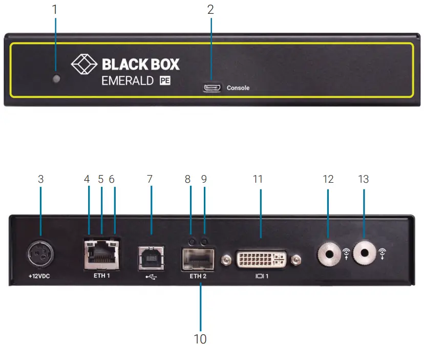
TABLE 1. EMD2000PE-T COMPONENTS
| NUMBER IN DIAGRAM AT LEFT | DESCRIPTION | DESCRIPTION |
| 1 | Power LED | Lights when power is ON |
| 2 | Micro USB connector | For future use |
| 3 | 12 VDC Power In connector | Connects to supplied power adapter |
| 4 | TP port Speed LED | Indicates 10/100/1000 Mbps |
| 5 | RJ-45 PoE port | Connects to network and supports Power over Ethernet (PoE) |
| 6 | TP port Activity LED | Indicates activity on the link |
| 7 | USB Type B connector | Connects to PC/workstation USB connector |
| 8 | Fiber port Speed LED | Indicates 10/100/1000 Mbps |
| 9 | Fiber port Activity LED | Indicates activity on the link |
| 10 | SFP cage | Holds fiber network SFP module |
| 11 | DVI Video connector | Connects to PC Video |
| 12 | Audio Line In | Connects to speakers |
| 13 | Audio Line Out | Connects to microphone |
NOTE: Unit automatically powers on when plugged in; must be powered off at the power source.
Receiver Diagrams
STEP 2A
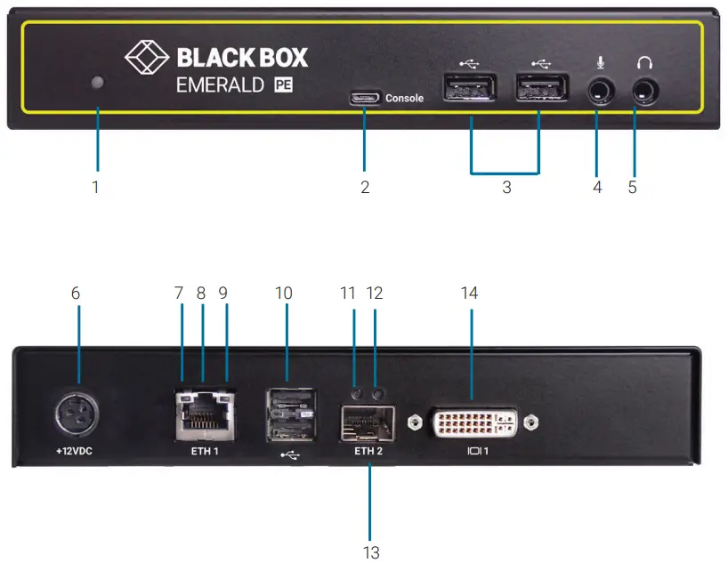
TABLE 2. EMD2000PE-R-P COMPONENTS
| NUMBER IN DIAGRAM AT LEFT | DESCRIPTION | DESCRIPTION |
| 1 | Power LED | Lights when power is ON |
| 2 | Micro USB connector | For future use |
| 3 | (2) USB Type A connectors | Connect to USB peripherals |
| 4 | Microphone | Connects to microphone |
| 5 | Speakers | Connects to speakers |
| 6 | 12 VDC Power In connector | Connects to supplied power adapter |
| 7 | TP port Speed LED | Indicates 10/100/1000 Mbps |
| 8 | RJ-45 PoE port | Connects to network and supports Power over Ethernet (PoE) |
| 9 | TP port Activity LED | Indicates activity on the link |
| 10 | (2) USB Type A connectors | Connect to USB peripherals |
| 11 | Fiber SFP port Speed LED | Indicates 10/100/1000 Mbps |
| 12 | Fiber SFP port Activity LED | Indicates activity on the link |
| 13 | SFP cage | Holds fiber network SFP module |
| 14 | DVI Video connector | Connects to monitor |
NOTE: Unit automatically powers on when plugged in; must be powered off at the power source.
Install SFPs in the SFP cages
STEP 3
INSTALL AN SFP MODULE IN THE TX
- Plug a compatible SFP in the SFP slot on the transmitter unit (TX).
NOTE: See Table 3 for a list of compatible SFPs (ordered separately).
INSTALL AN SFP MODULE IN THE RX
- Plug a compatible SFP in the SFP slot on the receiver unit (RX).
NOTE: See Table 3 for a list of compatible SFPs (ordered separately).
TABLE 3. COMPATIBLE SFPS
| PART NUMBER | DESCRIPTION | DISTANCE |
| 1-Gbps Connections | ||
| LFP441 | SFP, Gigabit Ethernet, 850-nm Multimode Fiber, LC | 550 m |
| LFP442 | SFP, Gigabit Ethernet, 1310-nm Singlemode Fiber, LC | 20 km |
| LFP443 | SFP, 10/100/1000BASE-T RJ-45 SGMII | 100 m |
| LFP411 | SFP, 1.25-Gbps, 850-nm Multimode Fiber, LC | 550 m |
| LFP413 | SFP, 1.25-Gbps 1310-nm Singlemode Fiber, LC | 10 km |
| LFP414 | SFP, 1250 Ext. Diag. 1310-nm Singlemode Fiber, LC | 30 km |
| LFP415 | SFP, 1.25-Gbps Copper RJ-45, SerDes | 100 m |
| LFP416 | SFP, 1250 Ext. Diag. 10/100/1000 RJ-45 SGMII | 100 m |
NOTE: The EMD2000PE-K kit contains one TX (EMD2000PE-T) and one RX (EMD2000PE-R-P).
Connect Power via External Power Supply
STEP 4A
CONNECT POWER USING POE
- Connect all computer cables to the Transmitter.
- Plug the POE enabled network cable into the transmitter; power will be enabled immediately.
- Connect the monitor and peripheral devices into the receiver.
- Plug the POE enabled network cable into the receiver; power will be enabled immediately
Connect the Peripherals
CONNECT THE TRANSMITTER
- Attach the Emerald PE Transmitter to the target PC/workstation using DVI and USB Type B cables.
- Connect to the LAN using standard CATx UTP or fiber cables to the local network connection.
CONNECT THE RECEIVER
- Attach the monitor, keyboard, mouse, USB and audio devices to the Emerald PE Receiver.
- Connect to the LAN using standard CATx UTP or fiber cables to the local network connection.
Starting Up and Default Settings
STARTING UP
- Once everything is connected, the unit automatically powers on when it is plugged in via a power adapter or PoE.
- The Graphical User Interface (GUI) will appear on the screen.
- Enter the default administrator user name and password.
User name: admin
Password: blank (just press the Enter key) - The default network setting for the Emerald PE Receiver uses a preconfigured static IP address.
- If you require the unit to be set to use DHCP, select the Control tab on the GUI and then choose the Network option. Select the DHCP option and click Apply.
DEFAULT SETTINGS
Default Settings:
- Transmitter IP Address: 192.168.1.22
- Receiver IP Address: 192.168.1.21
- Type: Static
- Subnet Mask: 255.255.255.0
- Default Gateway: 0.0.0.0
- Admin username: admin
- Admin password: no password, it is blank by default
- Ports Used: 3389
IMPORTANT: Do not lose the admin password once configured; there is no way to reset or retrieve it. The Emerald PE receiver has the option to create a second administrator account as a secondary entrance.
Point-to-Point Installation
POINT-TO-POINT INSTALLATION
In a point-to-point configuration, no administrator setup of the Emerald PE Transmitter or the Emerald PE receiver is required. This enables you to install the system quickly, directly out of the box. In the point-to-point configuration, you can install only one transmitter and receiver pair on a subnet and both must be on the same subnet unless a router is present in the network to span subnets. To span across different subnets, you will need to have admin rights to both routers on either side of the installation
and setup port forwarding for port “3389” for Remote Desktop.
If further configuration is required to change the default IP addresses, you can access the transmitter’s network settings through the remote unit:
- Simply connect the transmitter to the receiver using a CATx cable (but do not power up the transmitter yet), then connect a keyboard, monitor, and mouse to the remote unit (remote unit is on at this time).
- Login as “admin” and go to (Control)>> (Transmitter)>> (Discover) and follow the on-screen steps.
- It will advise you to connect both devices together and then power up the transmitter and press the “Next” button.
- It will take several minutes to discover the transmitter, but once found, you can modify the network parameters.
Matrix Installation and Getting Started
MATRIX INSTALLATION
In a matrix installation, every Emerald PE transmitter and receiver requires its own IP address. By default, the DHCP setting is set to static, so the addresses will need to be configured manually:
- Always configure the transmitter first by connecting the transmitter to the receiver using a CATx cable (but do not power up the transmitter yet), then connect a keyboard, monitor, and mouse to the remote unit (remote unit is on at this time).
- Login as “admin” on the remote unit and go to (Control)>> (Transmitter)>> (Discover) and follow the on-screen steps.
- It will advise you to connect both devices together, and then power up the transmitter and press the “Next” button.
- It will take several minutes to discover the transmitter, but once found, you can modify the network parameters.
- Once the transmitter is configured, you can now configure the receiver.
- If the units are on different subnets, then routers will need to be used to properly direct traffic.
GETTING STARTED
Once the IP addresses have been configured, each receiver will need to be configured for users, user passwords, user access rights and default video resolutions. You can access these settings from the receiver’s OSD (reboot the receiver and login as admin) and begin configuring these parameters.
NOTE: Each receiver can support a maximum of 32 users and a maximum of 32 targets (virtualized or transmitter).
Download the User Manual (Optional)
The full user manual/installation guides can be downloaded from the Black Box Web site
FOR US, AUSTRALIA NEW ZEALAND, AND CANADA
- Go to BLACKBOX.COM
- Enter the part number in the search box (for example, EMD2002PE-T).
- Click on the product in the “Products” page.
- Click on the “Support” tab on the product page and select the document you wish to download.
FOR OTHER COUNTRIES
- Go to BLACK-BOX.EU/SUPPORTCENTER
- Enter the part number in the search box and check the file type: application diagram, datasheet, firmware or manual.
- Select the document you want to download.
Support
Contact our free, 24/7 technical support in the US at 877-877-2269 or [email protected]
For other countries, go to BLACKBOX.COM/CONTACT-US


