BLACK BOX KVXLC-100 KVX Series DVI KVM Extender User Manual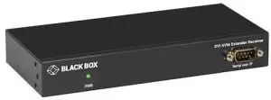
QUICK INSTALLATION GUIDE
Follow these steps to install the extender:
- If you have the fiber models, install the SFPs in the transmitter and receiver. Compatible SFPs from Black Box are listed in the table below.
COMPATIBLE SFP MODULES
PART NUMBER
DESCRIPTION
DISTANCE
1-GBPS CONNECTIONS
LFP441 SFP 1.25-Gb, 850-nm Multimode Fiber, LC 550 m LFP442 SFP 1.25-Gb, 1310-nm Single-mode Fiber, LC 20 km LFP412 SFP with Extended Diagnostics – 1250-Mbps Multimode Fiber, 1310-nm 2 km LFP413 SFP with Extended Diagnostics – 1250-Mbps Single-Mode Fiber, 1310-nm 10 km LFP414 SFP with Extended Diagnostics – 1250-Mbps, Singlemode Fiber, 1310-nm 30 km LFP416 SFP 1250-Mbps, Extended Diagnostics, 10/100/1000BASE-T, SGMII Interface, RJ-45 100 m NOTE: Other SFPs may work but have not been validated by Black Box, we recommend you use the suggested SFPs to avoid technical incompatibilities.
NOTE: SFP is not included, must be ordered separately - Connect the video source(s) to the Transmitter (Computer Unit).
- Connect the monitor(s) to the Receiver unit.
- Use CATx cables (EIA/TIA 568B industry standard compliant) or fiber cables for connection between Transmitter/Receiver.
- Apply the proper power to all connecting devices
NOTES:
- We recommend using the highest quality materials (cables, SFP, etc.) to ensure optimal transmission quality.
- If the screen does not display when you connect the computer:
- Make sure the device cables are correctly and firmly attached.
- Set your display device’s (TV, monitor, etc.) input source as DVI.
- Check the PC BIOS configuration of the video output setting.
- Connect your video source to the Display DIRECTLY to check if the video signal gets through.
CHAPTER 1: SPECIFICATIONS
| TABLE 1-1. TRANSMITTER SPECIFICATIONS | |
| Console Connection | |
| Video Output | N/A |
| Serial Control Port | N/A |
| Host Connection | |
| Video Input | KVXLC-100, KVXLCF-100: (1) DVI-I female; KVXLC-200, KVXLCF-200: (2) DVI-I female |
| Local Out Video Connection | |
| Local Out | KVXLC-100, KVXLCF-100: (1) DVI-I female; KVXLC-200, KVXLCF-200: (2) DVI-I female |
| Link Port | |
| RJ-45 | KVXLC-100: (1) RJ-45 using CATx cable – max. length: 330 feet (100 meters); KVXLC-200: (2) RJ-45 using CATx cable – max. length: 330 feet (100 meters) |
| SFP | KVXLCF-100: (1) SFP cage using Fiberoptic cable – max. length: 18.6 miles (30 km), depending on SFP; KVXLCF-200: (2) SFP cages using Fiberoptic cable – max. length: 18.6 miles (30 km), depending on SFP NOTE: SFP is not included. Must be ordered separately. |
| USB Interface | |
| Host | (1) USB Type B female |
| Device | N/A |
| Audio | |
| 2-way analog audio | (1) Line In, (1) Line Out |
| General | |
| LED indicator | Power: White LED |
| DDC Supported | DDC, DDC2, DDC2B |
| Max. Video Resolution | 1920 x 1200 @ 60 Hz |
| OS Compatibility | OS Independent |
| Housing material | Chassis Metal |
| Operating Temperature | 32 to 122° F (0 to 50° C) |
| Storage Temperature | -4 to +140° F (-20 to +60° C) |
| Relative Humidity | 0 to 80% |
| Power Supply | External 5-VDC, 2-A power supply |
| Dimensions | KVXLC-100, KVXLCF-100 transmitters: 1.06″ H x 7.09″ W x 3.27″ D (2.7 x 18.0 x 8.3 cm); KVXLC-200, KVXLCF-200 transmitters: 1.71″ H x 7.09″ W x 3.27″ D (4.4 x 18.0 x 8.3 cm) |
| Weight | KVXLC-100 transmitter: 0.79 lb. (0.36 kg); KVXLCF-100 transmitter: 0.77 lb. (0.35 kg); KVXLC-200, KVXLCF-200 transmitter: 1.12 lb. (0.51 kg) |
TABLE 1-2. RECEIVER SPECIFICATIONS
| Console Connection | |
| Video Output | KVXLC-100, KVXLCF-100: (1) DVI-I female; KVXLC-200, KVXLCF-200: (2) DVI-I female |
| Serial Control Port | (1) DB9 male |
| Host Connection | |
| Video Input | N/A |
| Link Port | |
| RJ-45 | KVXLC-100: (1) RJ-45 using CATx cable – max. length: 330 feet (100 meters); KVXLC-200: (2) RJ-45 using CATx cable – max. length: 330 feet (100 meters) |
| SFP | KVXLCF-100: (1) SFP cage using Fiberoptic cable – max. length: 18.6 miles (30 km), depending on SFP; KVXLCF-200: (2) SFP cages using Fiberoptic cable – max. length: 18.6 miles (30 km), depending on SFP NOTE: SFP is not included. Must be ordered separately. |
| USB Interface | |
| Host | N/A |
| Device | (2) USB 2.0 Type A female for USB device extension; (2) USB HID ports for keyboard and mouse |
| Audio | |
| 2-way analog audio | (1) MIC In, (1) Speaker Out |
| General | |
| LED indicator | Power: White LED |
| DDC Supported | DDC, DDC2, DDC2B |
| Max. Video Resolution | 1920 x 1200 @ 60 Hz |
| OS Compatibility | OS Independent |
| Housing material | Chassis Metal |
| Operating Temperature | 32 to 122° F (0 to 50° C) |
| Storage Temperature | -4 to +140° F (-20 to +60° C) |
| Relative Humidity | 0 to 80% |
| Power Supply | External 5-VDC, 2-A power supply |
| Dimensions | KVXLC-100, KVXLCF-100 receivers: 1.06” H x 7.09” W x 3.27” D (2.7 x 18.0 x 8.3 cm); KVXLC-200, KVXLCF-200 receivers: 1.71” H x 7.09” W x 3.27” D (4.4 x 18.0 x 8.3 cm) |
| Weight | KVXLC-100 receiver: 0.84 lb. (0.38 kg); KVXLCF-100 receiver: 0.81 lb. (0.37 kg); KVXLC-200, KVXLCF-200 receiver: 1.12 lb. (0.51 kg) |
CHAPTER 2: OVERVIEW
INTRODUCTION
The KVX Series DVI KVM Extender enables you to locally use one or two DVI/VGA monitors, USB keyboard/mouse/other devices, speaker, and microphone to operate a remote computer, server or other IT device. There are four models of the KVX Series DVI KVM
Extender: a single-head KVXLC-100 and dual-head KVXLC-200 version via a CATx link, and a single-head KVXLCF-100 and dual-head KVXLCF-200 version via a fiberoptic link. Each extender consists of a transmitter (TX) and a receiver (RX)
FEATURES
- Supports DVI and VGA input/output video quality up to 1920 x 1200 @ 60 Hz.
- Provides remote access for video/USB/RS-232/audio extension distance up to 330 feet (100 meters) over CATx cable for model KVXLC-100 or KVXLC-200; up to 18.6 miles (30 km) over fiberoptic cable for model KVXLCF-100 or KVXLCF-200, depending on the SFP used.
- The DVI KVM Console Extender lets you control a server, or computer over single-mode or multimode fiber optic cable at distances of up to 30 km (depending on the SFP used, fiber type, and fiber bandwidth*).
- Single-head models with (1) DVI connector and dual-head models with (2) DVI connectors are available.
- Offers transparent USB 2.0/1.1 extension.
- Uses analog audio LINE-IN/LINE-OUT extension.
- Supports bi-directional RS-232 control communication.
- Firmware upgradable.
NOTE: Reference the supported SFP chart.
WHAT’S INCLUDED
KVXLC-100:
- (1) Transmitter (TX)
- (1) Receiver (RX)
- (2) 5V, 2A Power Supplies (includes US, EU, and UK plug types)
- (1) DVI-D cable 1.8m (6 ft.)
- (1) 3.5mm audio cable 1.8m (6 ft.)
- (1) USB-B to USB-A cable 1.8m (6 ft.)
- (2) Deskmount Kits with Screws (KVXLC-DMK)
KVXLCF-100:
- (1) Transmitter (TX)
- (1) Receiver (RX)
- (2) 5V, 2A Power Supplies (includes US, EU, and UK plug types)
- (1) DVI-D cable , M/M 1.8m (6 ft.)
- (1) USB Type A to B cable, M/M 1.8m (6 ft.)
- (1) 3.5mm Dual Audio/Mic cable, M/M 1.8m (6 ft.)
- (2) Deskmount Kits with Screws (KVXLC-DMK
KVXLC-200:
- (1) Transmitter (TX)
- (1) Receiver (RX)
- (2) 5V, 2A Power Supplies (includes US, EU, and UK plug types)
- (2) DVI-D cables 1.8m (6 ft.)
- (1) USB Type A to B Cable, M/M 1.8m (6 ft.)
- (1) 3.5mm Dual Audio/Mic cable, M/M 1.8m (6 ft.)
- (2) Deskmount Kits with Screws (KVXLC-DMK)
KVXLCF-200:
- (1) Transmitter (TX)
- (1) Receiver (RX)
- (2) 5V, 2A Power Supplies (includes US, EU, and UK plug types)
- (2) DVI-D cables, M/M 1.8m (6 ft.)
- (1) USB Type A to B cable, M/M 1.8m (6 ft.)
- (1) 3.5mm Dual Audio/Mic cable, M/M 1.8m (6 ft.)
- (2) Deskmount Kits with Screws (KVXLC-DMK)
HARDWARE DESCRIPTION
TRANSMITTER
FRONT PANEL
Figure 2-1 shows the front panel that is common to the single-head CATx and fiber transmitters. Table 2-1 describes its components.
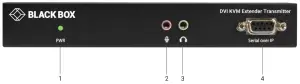
FIGURE 2-1. TRANSMITTER FRONT PANEL
Figure 2-2 shows the front panel that is common to the dual-head CATx and fiber transmitters. Table 2-1 describes its components.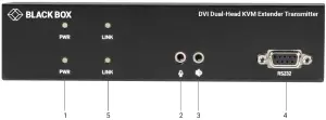
FIGURE 2-2. DUAL-HEAD TRANSMITTER FRONT PANEL
TABLE 2-1. TRANSMITTER FRONT-PANEL COMPONENTS
| NUMBER IN FIGURE 2-1 OR 2-2 | COMPONENT | DESCRIPTION |
| 1 | PWR LED | Lights when power to the transmitter is ON |
| 2 | Audio jack | Connects to analog audio input for audio extension |
| 3 | Audio jack | Connects to analog audio output for audio extension |
| 4 | DB9 female connector | Connects to source device’s RS-232 port for serial extension |
| 5 | Link LED | Lights when the TX/RX link is active |
BACK PANEL
Figures 2-3 and 2-4 show the back panels of the single-head CATx and fiber transmitters. Table 2-2 describes their components.
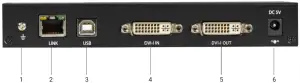
FIGURE 2-3. SINGLE-HEAD CATX TRANSMITTER BACK PANEL
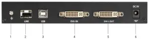
FIGURE 2-4. SINGLE-HEAD FIBER TRANSMITTER BACK PANEL
TABLE 2-2. SINGLE-HEAD TRANSMITTER BACK-PANEL COMPONENTS
| NUMBER IN FIGURE 2-3 OR 2-4 | COMPONENT | DESCRIPTION |
| 1 | Ground screw | Links to ground |
| 2 | For CATx model: RJ-45 connector For Fiber model: SFP cage | For CATx Model: CATx link For Fiber model: Install fiber SFP module here |
| 3 | USB Type B connector | Connects to source device’s USB port |
| 4 | DVI In port | Connects to source device’s signal for DVI/VGA extension |
| 5 | DVI Out port | Connects to local out |
| 6 | Power connector | Links to 5-VDC power supply |
Figures 2-5 and 2-6 show the back panels of the dual-head CATx and fiber transmitters. Table 2-3 describes their components.
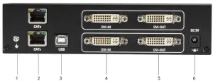
FIGURE 2-5. DUAL-HEAD CATX TRANSMITTER BACK PANEL
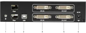
FIGURE 2-6. DUAL-HEAD FIBER TRANSMITTER BACK PANEL
TABLE 2-3. DUAL-HEAD TRANSMITTER BACK-PANEL COMPONENTS
| NUMBER IN FIGURE 2-5 OR 2-6 | COMPONENT | DESCRIPTION |
| 1 | Ground screw | Links to ground |
| 2 | For CATx model: (2) RJ-45 connectors For Fiber model: (2) SFP cages | For CATx Model: CATx links For Fiber model: Install fiber SFP modules here |
| 3 | USB Type B connector | Connects to source device’s USB port |
| 4 | (2) DVI In ports | Connect to source devices’ signals for DVI/VGA extension |
| 5 | (2) DVI Out ports | Connect to local out |
| 6 | Power connector | Links to 5-VDC power supply |
RECEIVER
FRONT PANEL
Figure 2-7 shows the front panel that is common to the single-head CATx and fiber receivers. Figure 2-8 shows the front panel that is common to the dual-head CATx and fiber receivers. Table 2-4 describes the components.
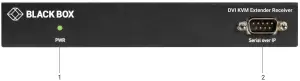
FIGURE 2-7. SINGLE-HEAD RECEIVER FRONT PANEL
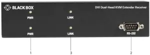
FIGURE 2-8. DUAL-HEAD RECEIVER FRONT PANEL
TABLE 2-4. RECEIVER FRONT-PANEL COMPONENTS
| NUMBER IN FIGURE 2-7 OR 2-8 | COMPONENT | DESCRIPTION |
| 1 | PWR LED | Lights when power to the receiver is ON |
| 2 | DB9 male connector | Connects to sink device’s RS-232 port for serial extension |
| 3 | Link LED | Lights when the TX/RX link is active |
BACK PANEL
Figures 2-9 and 2-10 show the back panels of the single-head CATx and fiber receivers. Table 2-5 describes their components.
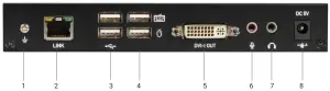
FIGURE 2-9. SINGLE-HEAD CATX RECEIVER BACK PANEL
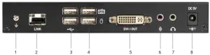
FIGURE 2-10. SINGLE-HEAD FIBER RECEIVER BACK PANEL
TABLE 2-5. SINGLE-HEAD RECEIVER BACK-PANEL COMPONENTS
| NUMBER IN FIGURE 2-9 OR 2-10 | COMPONENT | DESCRIPTION |
| 1 | Ground screw | Links to ground |
| 2 | For CATx model: (1) RJ-45 connector For Fiber model: (1) SFP cage | For CATx Model: CATx link For Fiber model: Install fiber SFP module here |
| 3 | (2) USB 2.0 ports | Connects to USB device’s ports for extension |
| 4 | (2) USB HID ports | Connects to USB keyboard and mouse |
| 5 | DVI Out port | Connects to sink device’s signal for DVI/VGA extension |
| 6 | Audio jack | Links to analog audio input for audio extension |
| 7 | Audio jack | Links to analog audio output for audio extension |
| 8 | Power connector | Links to 5-VDC power supply |
Figures 2-11 and 2-12 show the back panels of the dual-head CATx and fiber receivers. Table 2-6 describes their components.
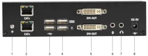
FIGURE 2-11. DUAL-HEAD CATX RECEIVER BACK PANEL
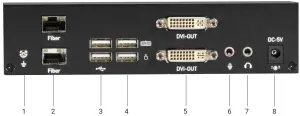
FIGURE 2-12. DUAL-HEAD FIBER RECEIVER BACK PANEL
TABLE 2-6. DUAL-HEAD RECEIVER BACK-PANEL COMPONENTS
| NUMBER IN FIGURE 2-11 OR 2-12 | COMPONENT | DESCRIPTION |
| 1 | Ground screw | Links to ground |
| 2 | For CATx model: (2) RJ-45 connectors For Fiber model: (2) SFP cages | For CATx Model: CATx links For Fiber model: Install fiber SFP modules here |
| 3 | (2) USB 2.0 ports | Connects to USB device’s ports for extension |
| 4 | (2) USB HID ports | Connects to USB keyboard and mouse |
| 5 | (2) DVI Out ports | Connect to sink devices’ signals for DVI/VGA extension |
| 6 | Audio jack | Links to analog audio input for audio extension |
| 7 | Audio jack | Links to analog audio output for audio extension |
| 8 | Power connector | Links to 5-VDC power supply |
CHAPTER 3: CONNECTION DIAGRAM
Figure 3-1 shows a typical connection.
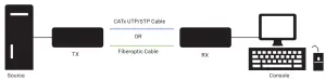
FIGURE 3-1. CONNECTION DIAGRAM
CHAPTER 4: INSTALLATION
FACTORY DEFAULT SETTINGS
Below are the factory default baud rate settings for the DVI KVM Extender’s serial ports.
- Baud rate: 115,200 bps
- Data bits: 8
- Parity: None
- Stop bits: 1
APPENDIX A: REGULATORY INFORMATION
A.1 FCC CLASS A STATEMENT
This equipment generates, uses, and can radiate radio-frequency energy, and if not installed and used properly, that is, in strict accordance with the manufacturer’s instructions, may cause interference to radio communication. It has been tested and found to comply with the limits for a Class A computing device in accordance with the specifications in Subpart B of Part 15 of FCC rules, which are designed to provide reasonable protection against such interference when the equipment is operated in a commercial environment. Operation of this equipment in a residential area is likely to cause interference, in which case the user at his own expense will be required to take whatever measures may be necessary to correct the interference.
Changes or modifications not expressly approved by the party responsible for compliance could void the user’s authority to operate the equipment.
This digital apparatus does not exceed the Class A limits for radio noise emission from digital apparatus set out in the Radio Interference Regulation of Industry Canada.
APPENDIX B: DISCLAIMER/TRADEMARKS
DISCLAIME
Black Box Corporation shall not be liable for damages of any kind, including, but not limited to, punitive, consequential or cost of cover damages, resulting from any errors in the product information or specifications set forth in this document and Black Box Corporation may revise this document at any time without notice.
TRADEMARKS USED IN THIS MANUAL
Black Box and the Black Box logo type and mark are registered trademarks of Black Box Corporation.
Any other trademarks mentioned in this manual are acknowledged to be the property of the trademark owners.
NEED HELP?
LEAVE THE TECH TO US
LIVE 24/7
TECHNICAL
SUPPORT
1.877.877.2269


