Installation Instructions
7400 Series Surface Vertical Rod
![]() The screws (from item B to E), attach both machine & tapping screws for install selection in the accessory package.
The screws (from item B to E), attach both machine & tapping screws for install selection in the accessory package.
How to determine hand of door
Right – Hand Reverse Bevel Left – Hand Reverse Bevel
(RHR) (LHR)
Outside Outside
Push Side Push Side
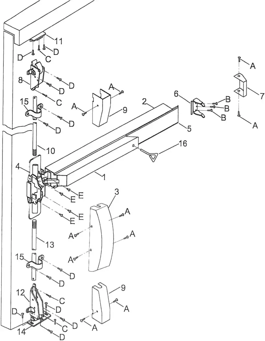
PARTS LIST | |||
ITEM | DESCRIPTION | Q’ty | Material |
| 1 | PUSH RAIL | 1 | Steel/S304 |
| 2 | MOUNTING RAIL | 1 | Steel/S304 |
| 3 | HEAD COVER | 1 | Zinc/S304 |
| 4 | CHASSIS ASS’Y | 1 | Steel |
| 5 | SLIDING SHIM | 1 | Steel/S304 |
| 6 | BRACKET | 1 | Steel |
| 7 | END CAP | 1 | Steel/S304 |
| 8 | TOP LATCH | 1 | Steel |
| 9 | LATCH COVER | 2 | Alum/S304 |
| 10 | TOP ROD | 1 | Alum/S304 |
| 11 | TOP STRIKE | 1 | S304 |
| 12 | BOTTOM LATCH | 1 | Steel |
| 13 | BOTTOM ROD | 1 | Alum/S304 |
| 14 | BOTTOM STRIKE | 1 | S304 |
| 15 | ROD GUIDE | 2 | S304 |
| 16 | ALLEN KEY | 1 | Steel |
| A | SM4X8 FLAT HEAD SCREWS | 10 | S304 |
| B | 10#X¾” ROUND HEAD SCREWS | 3 | Steel |
| C | 10#X¾” FLAT HEAD SCREWS | 4 | Steel |
| D | 10#X5/8″ ROUND HEAD SCREWS | 12 | Steel |
| E | 10#X¾” FLAT HEAD SCREWS | 4 | Steel |
2013, Jan.
![]() The screws (from item B to D), attach both machine & tapping screws for install selection in the accessory package.
The screws (from item B to D), attach both machine & tapping screws for install selection in the accessory package.
How to determine hand of door
Right – Hand Reverse Bevel Left – Hand Reverse Bevel
(RHR) (LHR)
Outside Outside
Push Side Push Side
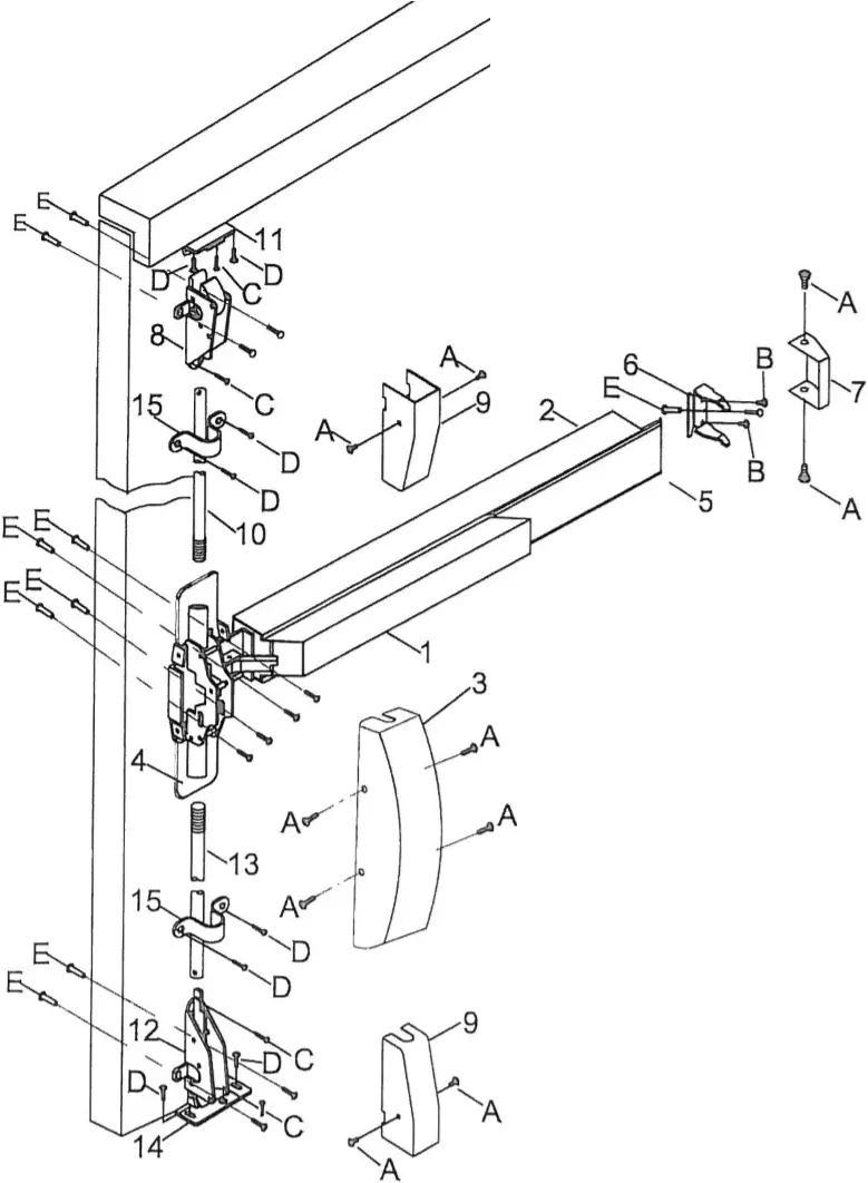
PARTS LIST | |||
| ITEM | DESCRIPTION | Q’ty | Material |
| 1 | PUSH RAIL | 1 | Steel/S304 |
| 2 | MOUNTING RAIL | 1 | Steel/S304 |
| 3 | HEAD COVER | 1 | Zinc/S304 |
| 4 | CHASSIS ASS’Y | 1 | Steel |
| 5 | SLIDING SHIM | 1 | Steel/S304 |
| 6 | BRACKET | 1 | Steel |
| 7 | END CAP | 1 | Steel/S304 |
| 8 | TOP LATCH | 1 | Steel |
| 9 | LATCH COVER | 2 | Alum/S304 |
| 10 | TOP ROD | 1 | Alum/S304 |
| 11 | TOP STRIKE | 1 | S304 |
| 12 | BOTTOM LATCH | 1 | Steel |
| 13 | BOTTOM ROD | 1 | Alum/S304 |
| 14 | BOTTOM STRIKE | 1 | S304 |
| 15 | ROD GUIDE | 2 | S304 |
| A | SM4X8 FLAT HEAD SCREWS | 10 | S304 |
| B | 10#X¾” ROUND HEAD SCREWS | 3 | Steel |
| C | 10#X¾” FLAT HEAD SCREWS | 4 | Steel |
| D | 10#X5/8″ ROUND HEAD SCREWS | 12 | Steel |
| E | 10#X¾” FLAT HEAD SCREWS | 4 | Steel |
2013, Jan.
7400 Series Surface Vertical Rod
STEP 1 MARK CETNER LINES
Mark Center Lines on INSIDE of door. Establish the horizontal center line of the device by drawing a line across the door 41″ (1041 mm) above floor line. Establish the top and bottom rod backset center line by drawing a vertical line from the top to bottom of the door measuring from the LOW SIDE of the DOOR BEVEL. After marking & drilling, please install pushbar according to its marked location. With establishment of pushbar, then go for next step of other installations.
Regularly furnished unless otherwise ordered.
INSIDE OF LHR DOOR Is ILLUSTRATED
- LOW SIDE OF DOOR BEVEL
- TOP OF DOOR
 for “FIRE RATED”: please drill 3/8″(9.6mm) hole for sex bolt for “NON-FIRE RATED”: please use screw C directly
- HINGE EDGE OF DOOR
- FLOOR LINE
- LATCH EDGE OF DOOR
- Determine backset “B” If lock stile is approx. 4½” wide or wider, backset “B” = 2¾” If lock stile Is less than 4½” wide, backset “B” = ½ of the visible width of the lock stile,
(when door is dosed against stop)
Regularly furnished unless otherwise ordered.
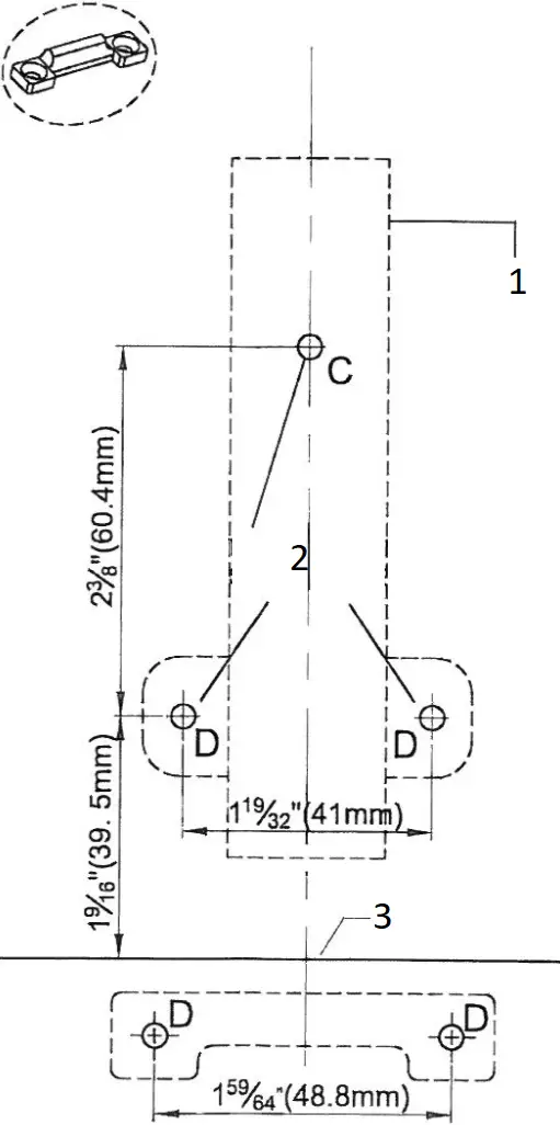
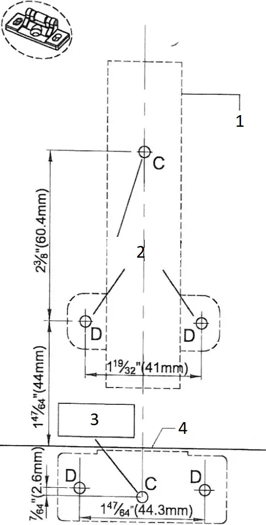
“A”DIMENSION | INSTALLATION | |
| 1-47/64” (44mm) | For Surface Strike | 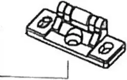 |
1-9/16” (39.5mm) | For Handicap Strike |
|
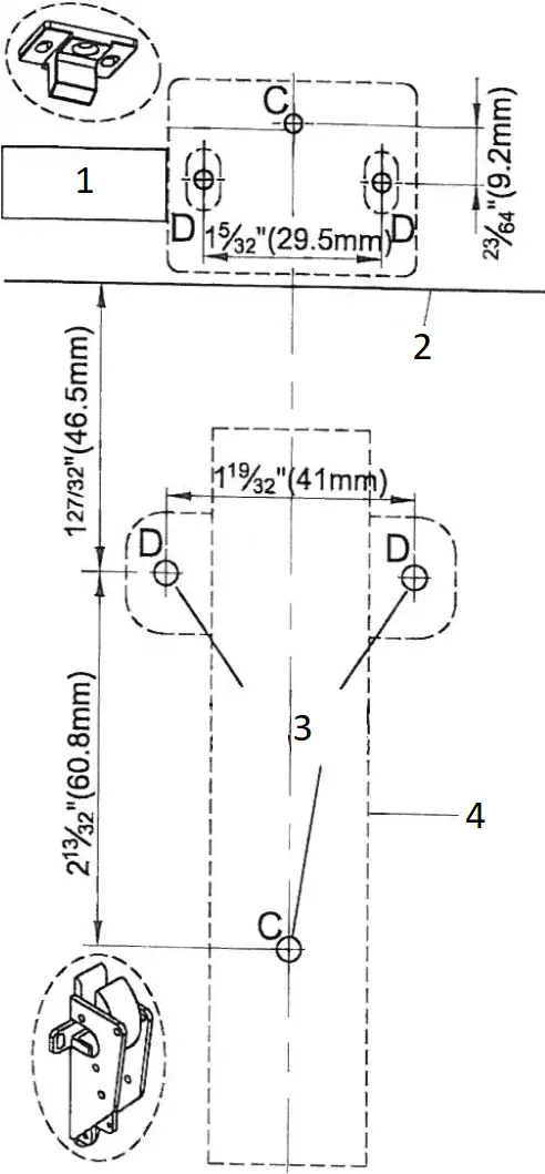
| 1-5/32” (29.5mm) | For Mortise in Strike | 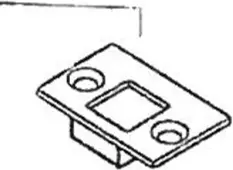 |
STEP 2 LOCATE TOP/BOTTOM LATCHES
Locate Top and Bottom Latch. Mark for later installation.
(See illustration on this Page for dimensions and locations.)
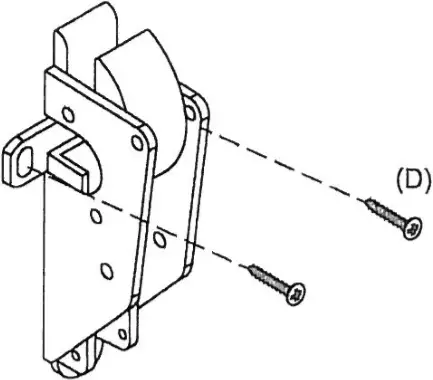
STEP 3 INSTALL TOP LATCH
Follow TEMPLATE to install top latch vertically.
Fix 2 screws (D) in the oval-shaped holes.
(DO NOT TIGHTEN screws (D) temporarily)
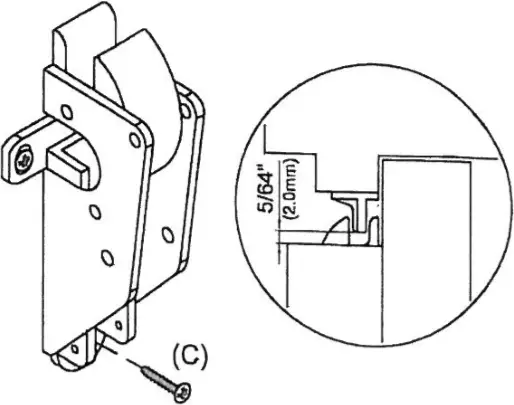
STEP 4 INSTALL TOP STRIKE
Follow TEMPLATE to install top strike vertically. After adjusting top latch to the proper gap between strike, which is about 5/64″ (2.0mm), tighten screws (D). Then, fix screw (C) and tighten it.
STEP 5 INSTALL BOTTOM LATCH
Follow TEMPLATE to install top latch vertically. Fix 2 screws (D) in the oval-shaped holes.
(DO NOT TIGHTEN screws (D) temporarily)
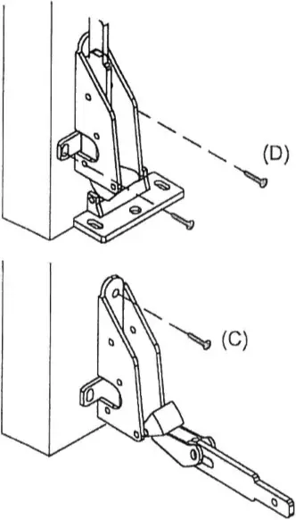
STEP 6 INSTALL BOTTOM STRIKE
Follow TEMPLATE to install bottom strike vertically. After adjusting bottom latch to the proper gap between strike, which is about 1/8″ (3.0mm), tighten screws (D). Then, fix screw (G) and tighten it.
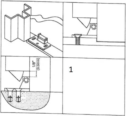
- ( Flush strike is for optional. Please use its TEMPLATE for installation)
STEP 7 INSTALL & ADJUST TOP ROD
The rod length can be adjusted by the thread of the rod.
Adjust it to the correct length when door is under closed position, by aiming the rod to the hole of the part (P).![]() If top rod had been cut to fit door height, please drill hole for pin loading.
If top rod had been cut to fit door height, please drill hole for pin loading.
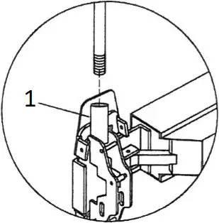
- rod connector
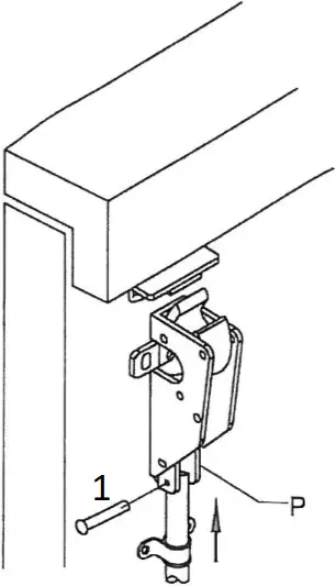
- pin
STEP 8 INSTALL & ADJUST BOTTOM ROD
The rod length can be adjusted by the thread of the rod. Adjust it to the correct length when door is under closed position, by aiming the rod to the hole of the part (Q).
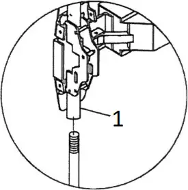
- rod connector
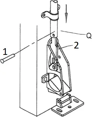
- pin
- rod connect plate
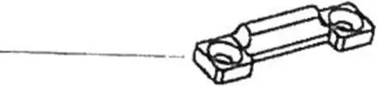
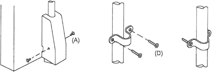
STEP 9 INSTALL LACTH COVERS & ROD GUIDE
(1). install latch covers and fix/tighten them with screws (A).
(2). Position rod guide midway between head cover and latch. Then, fix & tighten rod guide with screws (D).
STEP 10 TEST PUSH RAIL & THE DOGGING FUNCTION
- The latches should engage the strikes when the door is closed. If the door can be pushed open without depressing the push rail, please check the rod length / installation(starting from step 3)
- The latches should disengage from the strikes freely when the push rail is depressed or dogged down. If not, please check the rod length/installation again (starting from step 3)
- When applying outside trims:
(1). No trims: Exit only, latch bolts are retracted just by the push rail inside.
(2). Entry: latch bolts are retracted by trim outside after setting the trim unlocked.
(3). Storeroom: latch bolts are retracted by trim outside with key only.
(4). Passage: latch bolts are retracted by trim outside freely. - Dogging: Use alien key and turn clockwisely 90° when depressing push rail. Latch bolts will remain retraced.
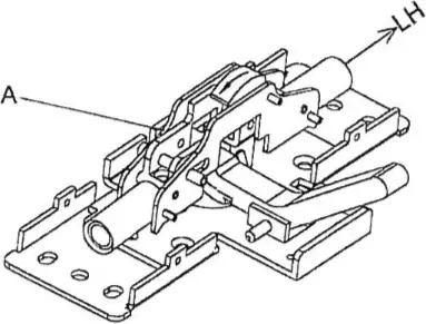
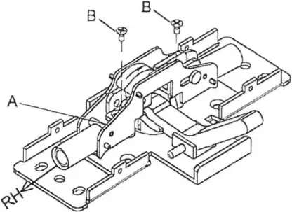
STEP 11 CHANGE HAND OF DEVICE
| 1. (EX: from LHR to RHR). Please follow next step to start the revere. | 2. (1). Remove screw B(*2). (2). Take part A off. |
| (LHR)
| 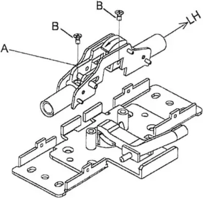 |
| 3. Turn 180° for part A | 4. (1)Screw and tighten B (2)The direction is now RHR. |
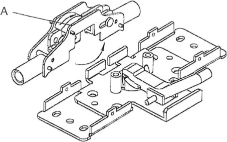 | (RHR)
|
TEMPLATE of Bottom LATCH (1:1)
[Handicap Strike (Optional use)]
2013, Jan
- OUTLINE OF BOTTOM CHASSIS
- LOCATION OF MOUNTING SCREW HOLES
- FOLD HERE ON DOTTED LINE
TEMPLATE of Bottom LATCH (1:1)
[Surface Strike (regular use)]
2013, Jan
- OUTLINE OF BOTTOM CHASSIS
- LOCATION OF MOUNTING SCREW HOLES
- Fix/tighten (D)firstly, then fix/tighten (E)
- FOLD HERE ON DOTTED LINE
TEMPLATE of Top LATCH (1:1)
[Top Strike (regular use)]
2013, Jan
- Fix/tighten (D)firstly, then fix/tighten (E)
- FOLD HERE ON DOTTED LINE
- LOCATION OF MOUNTING SCREW HOLES
- OUTLINE OF BOTTOM CHASSIS
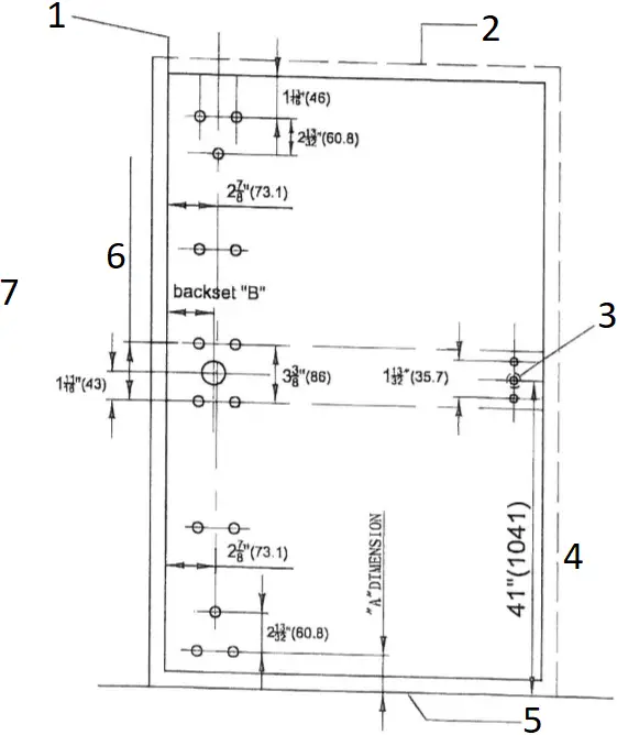
Template for 7400 Series
Surface Vertical Rod
(1:1)
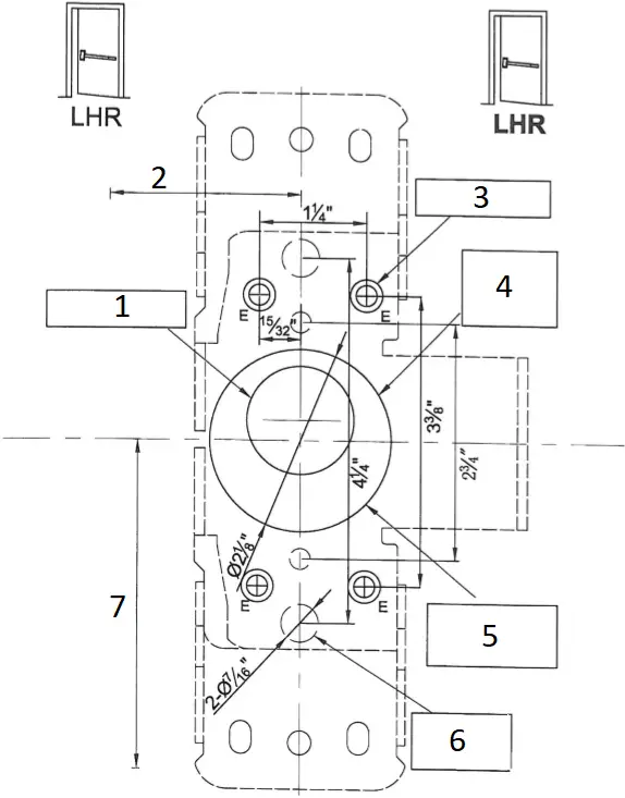
- IF CYLINDER ONLY IS USED.
DRILL 1 5/16″ (33) DIA. HOLE FROM INSIDE OF DOOR. - BACKSET SEE DEVICE DIRECTIONS
- FOR SEX BOLT DRILL 3/8″(9.6mm) HOLE OUTSIDE
- IF EXTERIOR ACCESS BY LEVER/KNOB TRIM DRILL 2 1/8″(54) DIAMETER HOLE
- This mounting hole is NO NEEDED if there is NO OUTSIDE TRIM application
- These special two labelled holes are designed for installation of specified out trim, please DO NOT drill the holes on door if the out trim is not needed to be fixed by them.
- 41″(1041)
TO FINISHED FLOOR
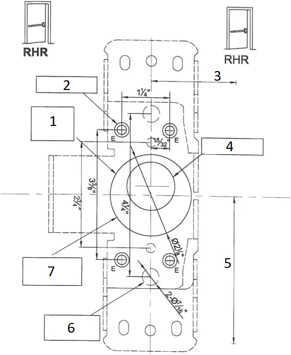
- IF EXTERIOR ACCESS BY LEVER/KNOB TRIM DRILL 2 1/8″(54) DIAMETER HOLE
- FOR SEX BOLT DRILL 3/8″(9.6mm) HOLE OUTSIDE
- BACKSET SEE DEVICE DIRECTIONS
- IF CYLINDER ONLY IS USED.
DRILL 1 5/16″ (33) DIA. HOLE FROM INSIDE OF DOOR. - 41″(1041)
TO FINISHED FLOOR - These special two labelled holes are designed for installation of specified out trim, please DO NOT drill the holes on door if the out trim is not needed to be fixed by them.
- This mounting hole is NO NEEDED if there is NO OUTSIDE TRIM application


