![]()
BLH-20KW Home Batteries 20kw Blauwhoff Energy Storage
User Manual
BLH-20KW Home Batteries 20kw Blauwhoff Energy Storage

V2.0
May 27,2022
BlauHoff BLH-5KW Battery LFP Battery User Manual
Dear customer,
This is your BlauHoff BLH-5KW Battery LFP battery for the home energy storage system. We provide safe, well-designed, and high-performance standard LFP battery packs for you. The battery pack is compact, easy to install, free of maintenance, and used as the building block of an energy storage system by assembling in parallel. It is widely applied in home applications, small commercial and industrial energy storage systems as well as Telecom stations.
This manual contains all the information necessary to install, use and maintain the LFP battery. We kindly ask you to read this manual carefully before using the product.
This manual is meant for the installer and the user of the LFP battery. Only trained and qualified staff may install and perform maintenance on the LFP battery.
The boundaries of its use, as described in this manual should be kept in mind. The LFP battery may not be used in medical or aviation-related applications. The LFP battery may not be used for any purposes other than described in this manual. Using the LFP battery for any other purpose will be considered improper use and will void the warranty of the product. BlauHoff cannot be held responsible for any damage caused by improper, incorrect, or unwise use of the product. Read and understand this manual completely
before using the product. During the use of the product, user safety should always be ensured, so installers, users, service personnel, and third parties can safely use the LFP battery.
This is the original manual, keep it in a safe location! Please consult [email protected] for the latest version of all manuals.
Before Using
Read and understand the following instructions:
Warning
- This equipment may only be installed, operated, and maintained by trained and qualified staff.
- The local safety regulations and relevant operating procedures must be observed during the installation, operation, and maintenance of the equipment, otherwise, the equipment may be damaged. The safety precautions mentioned in the manual are only intended to supplement local safety regulations.
Caution
- Do not dispose of batteries in a fire. The batteries may explode. Do not open or mutilate batteries. Released electrolyte is harmful to the skin and eyes. It may be toxic.3. A battery can present a risk of electric shock and burns by high shortcircuit current, Failed batteries can reach temperatures that exceed the bum thresholds for touchable surfaces: I-he following precautions should be observed when working on batteries: a) Disconnect the charging source before connecting or disconnecting battery terminals;b) do not wear any metal objects including watches and rings;c) do not lay tools or metal parts on top of batteries; and in addition, when the battery maintenance cannot be performed by an ordinary person, the following applies) use tools with insulated handles;e) wear rubber gloves and boots;
- determine if the battery Is either intentionally or Inadvertently grounded_ Contact with any part of a grounded battery can result in electric shock and burns by high short-circuit current. The risk of such hazards can be reduced if grounds are removed during installation and maintenance by an sk4lcd parson
- 8$ore moving or reconnecting the running >y rem, the pow must be off and the system should be shut down, otherwise, there will be Nik of electric shock
- Do not expose the U-ion battery to heat or fire. In case of fire, please use a dry powder fire extinguisher.
- Do not (*mantle any part of the system without contacting PYTES or PYTES authorized technical @veneers. System failure caused by such was not covered • the warrant
Danger
- Keep the Li-ion battery away from water, dust, and contamination, otherwise it may cause an explosion or other dangers and may even lead to personal injury.
- Do not short-circuit the Li-ion battery.
- Observe the plus (+) and minus (-) marks on the Li-ion battery and equipment and ensure correct use. Do not reverse-connect the Li-ion battery.
- Do not dismantle, crush, puncture, open, or shred the Li-ion battery.
- Before moving or reconnecting the running system, the power must be off and the system should be shut down, otherwise, there will be a risk of electric shock.
- Do not expose the Li-ion battery to heat or fire. In case of fire, please use a dry powder fire extinguisher. 7. Do not dismantle any part of the system without contacting PYTES or PYTES authorized technical engineers. System failure caused by such will not be covered by the warranty.
Specification
Table 1-1 Battery Pack Specifications
| Battery Model | BLH-5KW |
| Chemistry | LFP |
| Nominal Voltage | 51.2V |
| Voltage Range | 47.5V-57.6V |
| Nominal Capacity | 100Ah |
| Nominal Energy | 5.12kWh |
| Unit Dimension | L440mm* W620mm * H117mm(2.6U) |
| Unit Weight | 51kg |
| Standard Charge/DischargeCurrent | 50A |
| Maximum Charge/Discharge Current | 50A |
| Peak Current | 102A@15s |
| Round-Trip Efficiency | ≥95% |
| Communication Protocol | RS232, RS485, CAN |
| Cycle Life | ≥[email protected]/0.5C, 25℃ |
| Calendar Life | ≥10 years |
| Operating Temperature | Charge: 0℃~ 45℃, Discharge: -10℃~ 50℃ |
| Certificates | UL1973, IEC62619 / UN38.3 |
| Storage Temperature | Within 1month: -20~55°C 1-3months: -20~35°C 3-12months: 20~25°C |
1.1 Product standard configuration
| Items | Quantity | Specifications | Pictures |
| BLH-5KW | 1pcs | 51.2V/100Ah LFP pack; including BMS, three interfaces (CAN/RS-485/RS232), 2 Link ports, LED power indicator, and insulated coating metal case. |  |
| Power Cable | 1set | Connect battery to battery; 0.2m; Positive and negative |  |
| Communicate Cable | 1pcs | Connect battery to battery; 0.2m; CAN or RS485 communicate | |
| Earthing cable | 1pcs | 1m |
1.2 BMS function
| Protection and Alarm | Management and Monitor |
| Charge/Discharge End | Cell Balance |
| Charge over Voltage | Intelligent Charge Model |
| Charge/Discharge Over Current | Charge/Discharge Current Limit |
| High/Low Temperature | Capacity Retention Calculate |
| Short Circuit | Administrator Monitor |
| Power Cable Reverse | Operation Records |
2 Interface and protection functions
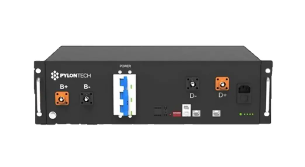
2.1 Battery front panel schematic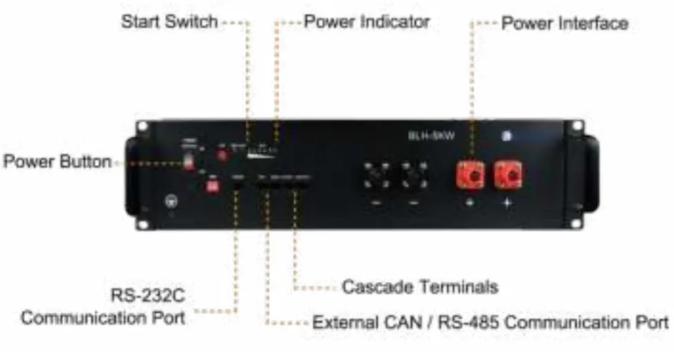
2.2 Components
| No. | Name | Label | Functions description |
| 1 | Ground | Grounding | |
| 2 | Power button | POWER | Power button. When switched to “ON”, the system can be activated by the “SW” key or external power supply; when switched to “OFF”,the system is off. |
| 3 | Soft start switch | SW | Press and hold this button for 1 second while the switch key is “ON” to enter Start or Sleep mode |
| 4 | DIP switch | ADD | Select the match manufacturer,see the match list(appendix A) |
| 5 | Running lights | RUN | Green lights. The lights flash when Standby. The lights are constantly on when charging. |
| The lights flash when discharging. | |||
| Alarm indicator | ALM | Red light. The lights flash when the Alarm. The lights are constantly on when protected. | |
| Capacity indicator | CHARGE | A total of 6 green lights show battery capacity, each representing 16.7% of SOC. | |
| 6 | External CAN communication port | CAN | Communication with external devices |
| 7 | External RS-485 communication port | RS485 | Communication with external devices |
| 8 | Cascade terminal | Link Port | Used for master-slave cascade communication. Connected with a standard direct-connected network cable, the master is connected to PORT1 and the the slave is connected to PORT0. |
| 9 | Input and output interface (negative) | “-“ | Negative input and output interface |
| 10 | Input and output interface (positive) | “+“ | Positive input and output interface |
![]() Warning
Warning
6.7,8,9.10 is DVC-A circuit, they shall not be connected to the DVC-B/C circuit when installed, or hazard shock will occur.
Operating Environment
- Battery operating environment requirements:
- Operating Temperature: -10 ℃~55℃
- Relative Humidity: 20%-80%, no condensation
- Altitude: <4000m
- Site environment requirements: Keep away from the heat source, avoid direct sunlight, no corrosive gas, no explosive gas, no insulating gas, no insulating conductive dust.
- Installed in a cabinet that shall not be opened without a tool or
- install in a restricted access area.
Packaging, transportation, and storage requirements
4.1 Transportation
Always check all applicable local, national, and international regulations before transporting an LFP battery.
During transportation, protected the battery from severe vibration, shock, or squeezing during transportation, as well as prevents sun and rain.
During the loading and unloading process, the battery should be handled lightly and protected against falling, rolling, and heavy pressure.
4.2 Storage
Follow the storage instructions in this manual to optimize the lifespan of the LFP battery during storage. If these instructions are not followed and the LFP battery has no charge remaining when it is checked, consider it to be damaged. Do not attempt to recharge or use it. Replace it with a new LFP battery.
See previous storage temperature conditions. The self-discharge of the LFP battery is 1-2% per month. Keep the battery SOC to40%-60% during storage. Disconnect the LFP battery from all loads and, if present, the charging device. Store the battery in a cool and dry place without direct sunshine. Keep the battery away from corrosive substances, inflammable and explosive material as well as hazardous gases. For long-term storage (> 6 months), charge the LFP battery to more than 80% of its rated capacity before storage. The battery needs to be recharged every 6 months to more than 80% of the rated capacity.
Installation and configuration
5.1 Installation Preparation
5.1.1 Safety Requirements
Only those who have been trained in the power system and have a good knowledge of the power system are allowed to install the device. Always observe local safety regulations and the safety requirements listed below during the installation process.
Before installing or removing the device, make sure that the power system is not powered and that the battery device is turned off. Distribution cabling should be reasonable and with protective measures to avoid being touched during operation.
5.1.2 Checking the operating environment
The operating environment should meet the requirements described in Chapter 3, “Operating Environment”. Otherwise, it needs to be adjusted and re-examined.
5.1.3 Tools
The tools that may be used are shown in Table 5-1.
Table 5-1 Tool
Tools | |
| Screwdriver (Slotted, Phillips) | Multimeter |
| Wrench | clip-on ammeter |
| Diagonal pliers | Insulating tape |
| Thermometer | Pliers |
| Anti-static wrist ring | Clip Pliers |
| Tapes | Strippers |
5.1.4 Technical preparation
Electrical interface settings:
If the battery is connected to the user device directly, please check:
- Whether the DC charging interface of the energy storage inverter meets the charging voltage and current requirements in Table 1-1 Battery Pack Specifications.
- Whether the power of the electrical equipment matches the parameters listed in “Table 1-1 Battery Pack Specifications”; Security check: Fire-fighting equipment such as portable dry powder fire extinguishers should be available near the equipment. Do not place dangerous materials such as flammable or explosive ones near the battery.
5.2 Unpacking
- When the battery arrives at the installation site, it must be loaded and unloaded properly and prevented from direct sunshine and rain. Before installation, check if there is any component missing according to the packing list attached in the packing box and check whether the box appearance is intact;
- Carefully handling during the unpacking. Protect the insulated coating on the case surface;
- Check the LFP battery for damage after unpacking. If there is any damage, contact BlauHoff or your reseller.
5.3 The preparatory work
- Make sure the POWER buttons of all batteries are OFF.
- Ensure the charging voltage of power supply equipment is DC57.5±0.1V;
- All power supply should be off.
5.4 Installation
5.4.1 Install the battery
The BLH-5KW can be installed either vertically or horizontally. This chapter, its main instructions for horizontal installation such as installation in a 19-inch cabinet. vertical installation is similar. All equipment must be placed steadily during installation.
5.4.2 Connect Ground cable
Unscrew the screw at the grounding hole on the front panel of the battery, wrap the ground cable around the screw, and tighten it with a screwdriver. Connect the other end of the ground cable to a reliable ground point.
External Bi-polar over current protection devices and Bi-polar external isolator shall be equipped The minimum diameter must be >10awg
Note: The grounding resistance should be less than 0.1Ω.
5.4.3 Connecting the power cable
Before connecting the power cable, connect and disconnect the cable to identify the positive and negative terminal, then make a mark respectively. After the cable is connected, measure whether there is a short-circuit or reverse connection.
Select the correct line based on your load by reference to the table below
| AWG | Area | Standard Current | Max. current | |
| (kcal) | (mm²) | (A) | (A) | |
| 5 | 33.1 | 16.8 | 66.2 | 75.5 |
| 6 | 26.3 | 13.3 | 52.5 | 59.9 |
| 7 | 20.8 | 10.5 | 41.6 | 47.5 |
| 8 | 16.5 | 8.37 | 33 | 37.7 |
| 9 | 13.1 | 6.63 | 26.2 | 29.8 |
| 10 | 10.4 | 5.26 | 20.8 | 23.7 |
It should be >10 AWG.
Connecting the power cables:
- Power cable connection instructions of Single-Rack:
- Single battery:
- Connect the positive and negative poles of the battery to the positive and negative terminal of the DC port of the energy storage inverter (or the junction box) with a red and black cable respectively.
- Multiple batteries (Max number 8):
The connection between batteries, as well as between the battery and ESS inverter are parallel. First, connect the two positive terminals of adjacent batteries with the red cable; and the two negative terminals of adjacent batteries with the black cable; then connect the positive and negative terminal of the battery with the positive terminal of the DC port of the energy storage inverter (or the junction box) with a red and black cable respectively; The capacity can be increased by connecting the batteries in parallel, but due to the limitations of BMS and power cable we supply, only two batteries can be connected in parallel and a bus bar should be used for connecting them together
![]() Warning: Batteries connected in series are forbidden, high voltage would lead to hazard shock.
Warning: Batteries connected in series are forbidden, high voltage would lead to hazard shock.
- Power cable connection instructions of Multi-Rack: Collect the positive and negative power cables respectively by the bus bar or junction box, then connect two racks in parallel. The length, thickness, material, and resistance of the cables connected in parallel must be the same.
Note: When the cable is inserted into the positive and negative terminals of the battery and “Click”, the cable is firmly connected. Before pulling out the cable, press the small button next to the terminal. When multiple batteries are connected in parallel, in order to reduce the influence of the circular current, the overall positive and negative output cables can be connected from different batteries.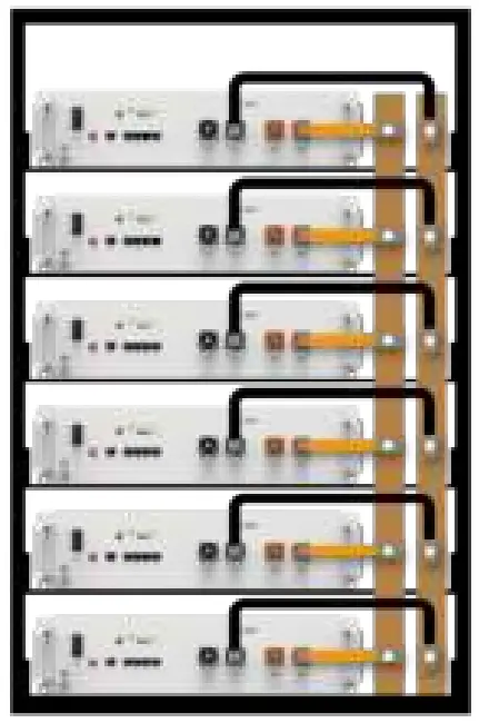
Figure 5-1 Schematic diagram of battery connection
Note: The battery must be placed in a locked cabinet or room, a 5cm cooling gap is reserved when installing the battery, and each layer of the battery cabinet should have a load capacity of more than 100kg.
5.4.4 Connecting communication cables
Single battery: Choose the port to be inserted according to the communication protocol (RS485/CAN/RS232) between the battery and ESS inverter, then insert the communication cables to the port; Multiple batteries: The host and the slave communicate in cascade mode: one is the host and the rest are the slaves. Please refer to the following picture for the cascade connection. Users need to inset communication cables to relevant link ports between batteries and be aware that: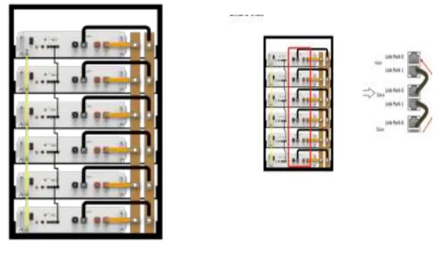
- The host Link Port 0 must be kept free;
- The end slave Link Port 1 must be kept free;
Note: The system may not be able to communicate if not follow the instruction.
Table 5-3 LED indications
| Battery status | Protection / Alarm / Normal | RUN | ALM | Capacity LED | Descriptions | |||||
| Shut down | OFF | OFF | OFF | OFF | OFF | OFF | OFF | OFF | All off | |
| Power-on | Normal | ON | ON | ON | ON | ON | ON | ON | ON | All light on one second at same time. |
| Standby | Normal | Flash 1 | OFF | OFF | OFF | OFF | OFF | OFF | OFF | Indication standby |
| Alarm | OFF | Flash 3 | OFF | OFF | OFF | OFF | OFF | OFF | Battery low voltage | |
| Charging | Normal | Light | OFF | Base on capacity | ||||||
| Alarm | Light | Flash 3 | ||||||||
| Protection | OFF | Light | OFF | OFF | OFF | OFF | OFF | OFF | Stop charging, protect start | |
| Discharge | Normal | Flash 3 | Flash 3 | Base on capacity | ||||||
| Alarm | Flash 3 | Flash 3 | ||||||||
| Protection | OFF | Light | OFF | OFF | OFF | OFF | OFF | OFF | Stop discharge, protect start | |
Note: The flashing instructions, flash 1-0.25s light/3.75s off; flash 2-0.5s light/0.5s off; flash 3-0.5s light/1.5s off.
Communication
There are RS-232C, RS485, and CAN communication ports on the battery. The battery status can be obtained and the battery’s internal parameters can be modified via a host computer.
CAN
CAN communication Terminal (RJ45 port) follows CAN protocol, to put battery information.
RS485
RS485 Communication Terminal:(RJ45 port) follow RS485 protocol, to output battery information.
RS232
RS232 Communication Terminal:(RJ45 port) follow RS232 protocol, to upgrade the software and communicate with your PC.
Link Port 0,1
Link Port0,1 Communication Terminal:(RJ45 port) follow CAN/RS485 protocol, to communicate between multiple parallel batteries.
6.1 RS232 port
Default baud rate of RS-232C ports: 115200bps.
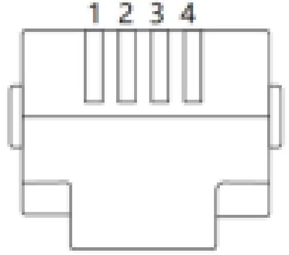
Table 6-1 RS232 Connector Pin Assignments
| Pin number | RS-232C port |
| 1 | GND |
| 2 | TXD |
| 3 | RXD |
| 4 | GND |
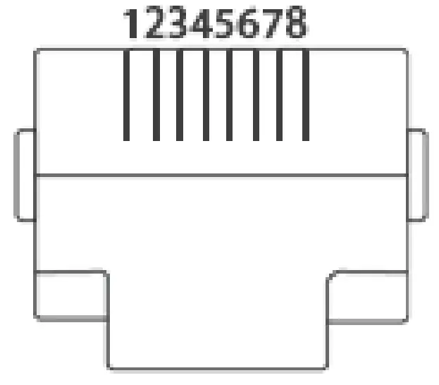
6.2 RS485 port and CAN port.
Default baud rate of RS-485 port: 9600bps Default baud rate of CAN port: 500K
Table 6-2 RS485 and CAN Connector Pin Assignments
| Pin number | Serial | CAN |
| 1 | RS485B | — |
| 2 | RS485A | GND |
| 3 | GND | — |
| 4 | — | CANH |
| 5 | — | CANAL |
| 6 | GND | — |
| 7 | RS485A | — |
| 8 | RS485B | — |
Troubleshooting
Please refer to the troubleshooting methods mentioned below. Please read the “Table 5 -3 LED indication” of this manual before troubleshooting to prevent false operations. For example, it doesn’t indicate the battery is faulty if the ALM alarm red light on the front panel is blinking or constantly on. When there is an “alarm” indication, it usually works well and needs no troubleshooting. When there is a “protection” indication, the battery will work normally automatically after the “protection” status is released.
Warning: Do not repair the battery if no authorization from BlauHoff!
7.1 Unable to start
| Problem | Troubleshooting Steps | Solution |
| 1. Confirm that the battery is turned on; | ||
| The battery cannot be charged properly when the battery is not fully charged. | 2. Check the power cord. Confirm that the power cables are correctly connected and the charging circuit is correct; 3. Check the battery indicator LED to see if the battery is under the “Protection” state. If so, unplug the battery power cord, find the cause of the protection, and fix the problem, then restart the battery; | If the battery still does not charge properly after following the above steps, please contact the local reseller or BlauHoff. |
| 4. Check if the charging voltage meets the battery charging requirements. If not, adjust the power supply voltage to the proper range. |
7.2 Unable to charge
| Problem | Troubleshooting Steps | Solution |
| 1. Confirm that the battery is turned on; | ||
| The battery cannot be discharged properly. | 2. Check the power cables to ensure that they are properly connected. 3. Unplug the battery power cable and measure the battery power output voltage. If the battery voltage is too low, charge it immediately. | If the battery still does not discharge properly after following the above steps, please contact the local reseller or BlauHoff. |
7.3 Unable to discharge
| Problem | Troubleshooting Steps | Solution |
| 1. Confirm that the battery is turned on; | ||
| The battery cannot be discharged properly. | 2.Check the power cables to ensure that they are properly connected. 3. Unplug the battery power cable and measure the battery power output voltage. If the battery voltage is too low, charge it immediately. 4. Check the battery indicator LED to see if the battery is under the “Protection” state. If so, unplug the battery power cables, find the cause of the protection, and fix the problem, then restart the battery; | If the battery still does not discharge properly after following the above steps, please contact the local reseller or BlauHoff. |
7.4 ALM indicator is always on
When the ALM indicator is constantly red and the other indicators are off, the battery is in the “Protection” state. When the condition-triggered protection is released, the battery will automatically return to normal operation. There are a few issues requiring immediate measures.
| Problem | Troubleshooting Steps | Solution |
| The ALM indicator is constantly red and all other indicators are off. | 1.Check the power cables to ensure that they are properly connected. 2. Check whether the charging voltage, charging/discharging current, battery/cell voltage and temperature meet the relevant protection conditions, and release the “protection” state to ensure that the voltage, current, and temperature are within the normal working range. | If the battery protection state cannot be released, or the ALM indicator is constantly on when the battery is properly charged after it is restarted, please contact your local reseller or BlauHoff. |
7.5 Battery designation
EXAMPLE 1 –ICP200/1 50/150/[7S]E/0+50/75 would designate a battery composed of 7S connected prismatic Li-ion secondary cells, with a cobalt-based positive electrode. Its cell maximum thickness is between 199 mm and 200mm, its cell maximum width is between 149 mm and 150 mm, and its cell overall height is between 149 mm and 150 mm. It is designed for a low discharge rate over a long period. Its low-temperature grade is 0°C. Its high-temperature grade is +50 °C. Its capacity after 500 cycles to rated capacity is between 75 % and 79 %. EXAMPLE 2 —NR54/222[4P3S]H/-20+50/80 would designate a battery composed of 4P-3S connected cylindrical Li-ion secondary cells, with a nickel-based positive electrode. Its cell maximum diameter is between 53mm and 54 mm, and its cell overall height is between 221 mm and 222 mm. It is designed for high discharge rate. Its low-temperature grade is -20 °C. Its high-temperature grade is +50 C. Its capacity after 500 cycles to rated capacity is between 80 % and 84%.
Warranty Card
| Battery model | Warranty Card | |
| Battery quantity | Inverter brand/model | |
| Battery using time | Inverter quantity | |
| PV arrays power | Inverter using time | |
| Problem description (including foul One, weather. condition. Inverter error code. Mc.) | ||
| Phots of battery wring | ||
| photos of inverter wiring and panels | ||
| The right of interpretation belongs to BlauHoff. | ||
![]()


