
PoEWit NS-8B 12-Port L3 Managed Switch
About Guide
This guide provides instructions to install the NS-8B switch
NOTE: The model you have purchased may appear slightly different from the illustrations shown in the document. Refer to the Product Instruction and Technical Specification sections for detailed information about your switch, its components, network connections, and technical specifications.
This guide is divided into four parts:
- About guide: Terminology/Usage
- Product introduction: Product overview and panel definitions
- Hardware installation: Step by step hardware installation process
- Technical specifications
Terminology / Usage
In this guide, the term “Switch” (first letter capitalized) refers to this PoE Switch, and “switch” (first letter lower case) refers to other PoE switches. Some technologies refer to terms “switch”, “bridge” and “switching hubs” interchangeably, and both are commonly accepted for Ethernet switches.
Note: Indicates important information that helps a better use of the device.
Warning: Indicates potential property damage or personal injury.
Copyright and trademark
The pictures and data shown in this guide are for reference only, subject to change without notice.
Product Introduction
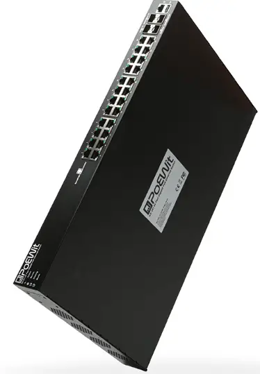
This Switch is a 10G Full Managed PoE Switch. It provides 8 x10/100/1000Mbps Auto-Negotiation RJ45 PoE ports and 4 x10Gbps SFP ports, which can satisfy the full speed forwarding of ports. The Switch uses 19” 1U standard chassis rack or can be used on the desktop.
Front Panel
The front panel consists of LED indicators and network ports.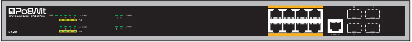
LED Lamp
Power LED: The Power LED lights up when the Switch is connected to a power source.
Link/Act indicator: The light indicates the network connection through the corresponding port. Flicker indicates that the switch is sending or receiving data.
PoE indicator: Blinking indicates that the PD device is connected to the corresponding port, and Off indicates that the port is not powered or no PD device is found.
Rear Panel
The rear panel view of the Switch consists of an AC power connector.
Plug the female connector into the Switch and male connector into a power outlet. Supports input voltages 100-240VAC, 50/60Hz.
Switch: Turn on the switch after inserting the power cord, “I” means to turn on, “O” means off.
Grounding: Use specialized ground lead connect.
HARDWARE INSTALLATION
This chapter provides unpacking and installation information for the Switch.
Open a Seal
Open the shipping carton and carefully unpack its contents. Please consult the packing list located in the User Manual to make sure all items are present and undamaged. If any item is missing or damaged, please contact us for replacement.
- Switch 1 pcs
- AC power cord 1 pcs
- Rubber feet 4 pcs
- Screws 6 pcs
- Mounting brackets 2 pcs
- User’s manual 1 pcs
- Serial port lines 1 pcs
Switch Installation
For safe switch installation and operation, it is recommended that you:
- Visually inspect the power cord to see that it is secured fully to the AC power connector.
- Make sure that there is proper heat dissipation and adequate ventilation around the switch.
- Do not place heavy objects on the switch.
Desktop Installation
When installing the switch on a desktop, the rubber feet included with the device must be attached on the bottom at each corner of the device’s base. Allow enough ventilation space between the device and the objects around it.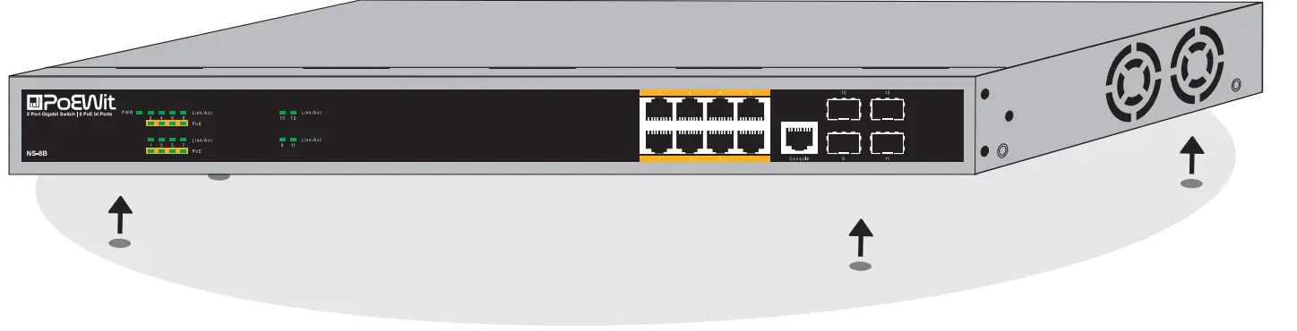
Rack Installation
The switch can be mounted on a EIA standard size 19-inch rack, which can be placed in a wiring closet with other equipment. To install, attach the mounting brackets to the switch’s side panels (one on each side) and secure them with the screws provided.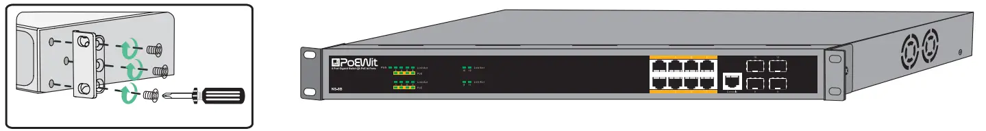
Then, use the screws provided with the equipment rack to mount the switch in the rack.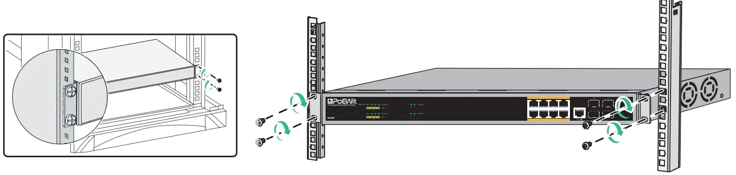
Plugging in the AC Power Cord
You can connect AC power supply cord to switch back and the other side to a power outlet (power outlet must be well grounded and support over voltage protection).
Warning: Do not turn on the power switch before power cables are connected. Power surge may cause damage to the Switch.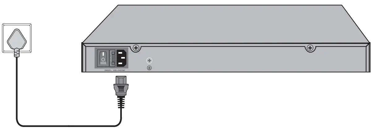
Using Web-based Management
After a successful physical installation, you can configure the Switch, monitor the network status, and display statistics using a web browser.
Supported Web Browsers
The embedded Web-based Management currently supports the following web browsers:
- Internet Explorer 6 or higher version
- Chrome
- Mozilla
- Firefox 1.5/2.0 or higher version
You will need the following equipment to begin the web configuration of your device:
- PC with a RJ-45 Ethernet connection
- Standard Ethernet network cable
With a standard Ethernet cable, connect the Ethernet cable to any of the ports on the front panel of the switch and to the Ethernet port on the PC.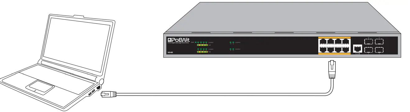
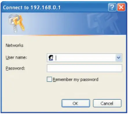
Login Web-based Management
- To access the GUI of the switch, open a browser and type the default management address http://192.168.0.1 in the address field of the browser, then press the Enter key.
Note:
- To log in to the switch, the IP address of your PC should be set in the same subnet as that of the switch. The IP address is 192.168.0.x (”x” is any number from 2 to 254). Subnet Mask is 255.255.255.0.

- Enter admin for both the User Name and Password in lower case letters. Then click the Login button or press the Enter key.

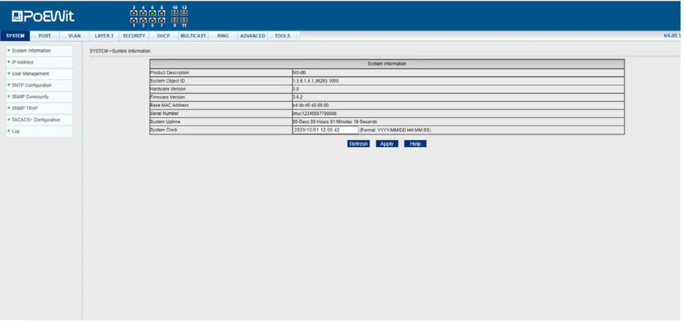
- After a successful login, the main page will appear as follows, and you can click the menu on the left side to configure the corresponding functions.


Note: For more details about how to configure the switch, see the User Guide on www.poewit.com.
TECHNICAL SPECIFICATIONS
| Project | Description |
| Fixed port | 8×10/100/1000Mbps PoE ports and 4x10Gbps SFP port |
| Standards and protocols | IEEE802.3 10Base-T Ethernet standard IEEE802.3u 100Base-TX Fast Ethernet standard IEEE802.3ab 1000Base-T Ethernet standard IEEE802.3z Gigabit Ethernet (fiber) IEEE802.3x Full duplex flow control and Backpressure Half duplex flow control IEEE802.3ab Link aggregation |
| Rate | 10/100/1000Mbps |
| LED Indicators | Power, Link/Act, PoE |
| AC Input Voltage Range | 100V~240V AC, 50/60Hz |
| Power consumption | 20W |
| Operating temperature | 0°C 40°C |
| Storage temperature | -10°C 70°C |
| Relative humidity | 20%~85% (non-condensing) |
| Switching Fabric | 96G |
| MAC Addresses | 16K |
| PoE Technology | |
| PoE Compliance | 100% IEEE 802.3af, 802.3at compliant, 802.3bt compliant |
| PoE Classification | PSE (Power Sourcing Equipment) |
| PoE Voltage | +52 VDC |
| PoE Power Budget | 500W |
| PoE Operation | Automatic detection and power management |
| PoE Port | 8 ports support Ultra PoE (90W max) |
| PoE Pin Assignments | V+ (Pin 3, 6,4,5), V- (Pin 1, 2,7,8) |
| PoE Disconnect Mode | DC disconnect |
| Software Technology | |
| Port Feature | Port Control, Port Isolation, Port Self-loop Detection |
| Port Mirroring | Multi to 1 Sniffer |
| VLAN | Port-base & 802.1q Tag-base VLANs |
| Link Aggregation | Up to 8 maximum aggregation groups, each containing up to 4GE |
| Traffic control | IEEE 802.3x full-duplex flow control |
| Rate Limit | Unit: 64kbps |
| Spanning Tree | Support STP, RSTP, MSTP |
| Ring Protocol | Support EAPS |
| Multicast | Support 256 Multicast groups, Support IGMP Snooping |
|
QoS | 4 output queues on each port |
| Support flexible queue scheduling algorithms: WRR, Q+WRR | |
| Support port-based / MAC-based / 802.1p / DSCP classification | |
| ACL | Support Standard IP / Extend IP / MAC IP / ARP, up to 512 entries |
|
Security | Support MAC-based 802.1X authentication |
| Support AAA/RADIUS authentication | |
| Support WEB/Telnet password protection | |
| Support Accessing privilege mode password protection | |
| SMNP | Support |
| Configuration File | Support Download/Upload configuration File via WEB |
| Upgrade Firmware | Support Upgrade Firmware via WEB |
| Management Interface | Support WEB, SNMP, CLI, Telnet, Console |
| Mechanical | |
| Casing | Metal |
| Dimensions (W x L x H) | 440 mm x 200 mm x 44 mm |
| Installation | Rack mounting or Desktop |


 Managed Switch Cli User Manual")


