![]() PU-28 Touch Screen Air Heater Control Panel
PU-28 Touch Screen Air Heater Control Panel
User Manual
Introduction
This Operating Manual contains general information for the user on safe maintenance and operation of the product.
In case of any problems, we strongly recommend that you contact authorised service centres, the addresses and phone numbers of which you can obtain from the seller or on the www.au-toterm.com website.![]() Before operating the product, read this operating manual and the heater operating manual.
Before operating the product, read this operating manual and the heater operating manual.
Warranty and liability
The manufacturer will not be liable for defects and dam- age caused by failure to follow the heater installation and maintenance instructions.
- The control panel can only be used to control liquid heaters Flow 5, Flow 6, Flow 10, Flow 14 and air heaters Air 2D, Air 4D, Air 9D.
- Do not connect and disconnect the control panel connector while the liquid/air heater is operating.
- After the product is switched off, it should not be switched on again for at least 5–10 seconds.
- For safe product operation, after two unsuccessful attempts to start the product in a row, contact the service department for troubleshooting information.
The warranty operating period and the conditions of warranty service are specified in the warranty certificate.
Safety
![]() DO NOT switch on and operate the liquid/air heater in locations where combustible vapours or gases or large amounts of dust can form and accumulate (for example, fuelling stations or petroleum, fuel, coal, timber, or grain storage facilities). Explosion hazard.
DO NOT switch on and operate the liquid/air heater in locations where combustible vapours or gases or large amounts of dust can form and accumulate (for example, fuelling stations or petroleum, fuel, coal, timber, or grain storage facilities). Explosion hazard.
Do not switch on and operate the product in enclosed or non-ventilated premises (sheds, garages, etc.). Hazard of poisoning and asphyxiation by exhaust gases.
Do not switch on and operate the product if combustible materials or fluids are present in the exhaust gas. Fire hazard.
Do not use a faulty product. Injury hazard due to the use of faulty device.
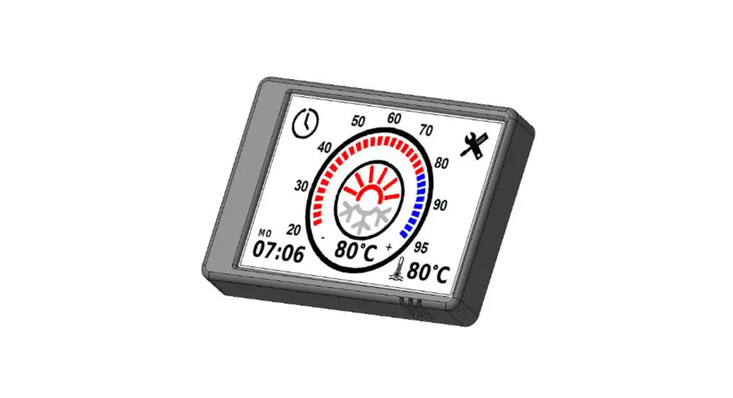
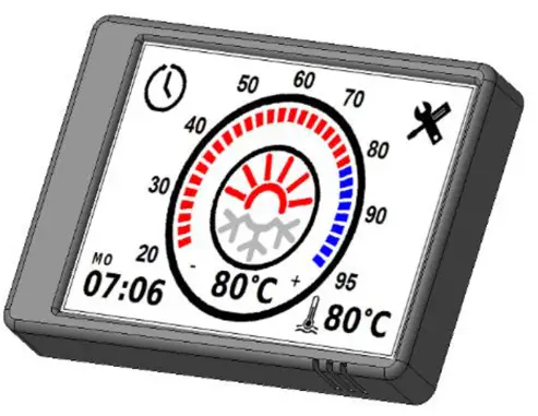
Control panel PU-28
 The control panel interface depends on the product it is connected to.
The control panel is designed for:
- manual start and shut-off of the product;
- manual start and shut-off of the pre-heater pump (for liquid heaters Flow 5, Flow 6, Flow 10, Flow 14);
- manual start and shut-off of ventilation (for air heaters Air 2D, Air 4D, Air 9D);
- fluid temperature display (for liquid heaters);
- power supply voltage display;
- current time and operating time display;
- setting of the liquid temperature heating limit/set-point (for the heater);
- activation of the product start-up timer;
- economy mode activation (for liquid heaters Flow 10, Flow 14);
- display of the software version of the control panel and heater;
- auxiliary heater operation mode selection (for liquid heaters);
- display of malfunction code in case of product malfunctions.
When power is supplied to the control panel, the time must be set
The front panel of the control panel has a capacitive touch screen that can be physically pressed (with a small amount of force). There is a button underneath the capacitive touch screen.
The touch screen responds to touch. The start-up/shut-down command is executed by physically touching the screen only if it has not been triggered by the capacitive touch screen.
Control panel operation
Once connected to the product, the control panel retrieves the op- erating settings from the product. It is necessary to verify whether the actual settings correspond to the desired settings.
- Main screen
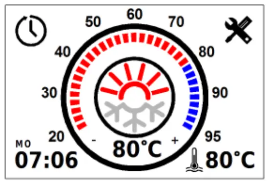
The main screen (Fig. 1) shows the current time in the lower left corner and the current heating medium/air temperature in the centre. A short tap in the bottom right corner switches between heating medium temperature, air temperature, and power supply voltage.
A long tap opens a graph showing changes in the temperature of the heating medium, air temperature, and power supply voltage over the last 7 days. To start the product (Fig. 2), tap the centre of the screen or press mechanically. Fig. 1. The main screen of a liquid heater and an air heater After the product has been started up, the countdown of the oper- ation time in minutes (Fig. 2) will begin at the bottom left of the screen. Switching between operation time and current time is done by short tapping on the operating time.
Set the temperature limit/set-point by moving the slider along the circumference of the temperature scale, or by tapping the ‘+’ and ‘-’ next to the current fluid temperature display (Fig. 3). During adjustment, the set-point value is also displayed in the centre of the screen. To shut the product down (Fig. 4), tap the centre of the screen or press mechanically. After the shut-down, the control panel switches to the main screen (Fig.1). When the control panel remains idle, it switches to standby mode to reduce the power consumption (Fig. 5).
The heater must not be disconnected from the power supply before the end of the purge cycle
- Operational features
A long tap (2 seconds) on the centre of the screen when a Flow 5, Flow 6, or Flow 10 heater is switched off will force the pump to start (without heating the coolant). For an air heater, a long tap triggers ventilation mode (without heating).
During Flow 10 and Flow 14 heater operation, a long tap switches the operating mode to economy mode.
During continuous operation at low setting, all products automatically restart every 3 hours. - Timers
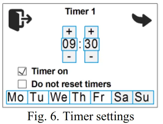
Tap to set up the timer. The control panel allows to program up to three start-up timers.
  switches between timers; Timer on – timer activation;
 Do not reset timers – the timer will not switch off after triggering.
The time is set by tapping the ‘+’ and ‘-’. exits the timer settings. - Control panel screen settings
Tap on the main screen (Fig. 1) to access the settings. Navigate between the menu pages by tap- ping .
Control panel screen settings (Fig. 7). The brightness can be adjusted using the Brightness slider. Sleep mode when running – turn the screen off while the product is in operation. To return from sleep mode, press or tap the screen. The time after which the remote control enters sleep mode can be adjusted from 30 sec, to 5 min. Show clock – display the current time and day of the week while the control panel is in sleep mode (only when the product is running).
 - Liquid heater settings
In auxiliary heater mode, the heater is operated in conjunction with the vehicle engine.
Pre-heater mode is intended for preheating the vehicle’s engine and/or passenger cabin. The heater can be pre-started using a timer or manually.
Heater operating mode settings (for Flow 5, Flow 6, Flow 10) (Fig. 8):
Auxiliary heater manual mode – manual auxiliary heater mode (not available on some software versions). If the heater is switched off, it will not start automatically after the engine is started. Auxiliary heater auto mode – automatic auxiliary heater mode. If the heater is switched off, it will start automatically after the engine is started. When the engine is stopped, the heater will switch off automatically. If the heater is switched on, it will automatically switch to the auxiliary heater mode when the engine is started.
Engine temperature – auxiliary heater temperature setting. The required temperature can be set between +75…+95 °C. The default setting is +85 °C.
Preheater temperature – the fluid temperature at which the heater enters standby mode (heater operation stops, pump operation continues). When the fluid temperature drops to the specified value, the heater exits the standby mode (heater operation is resumed). The default value for the standby temperature is +88 °C. The standby temperature can be set between +20…+95 °C.
Pump operating mode settings (for Flow 5, Flow 6, Flow 10) (Fig. 9):
Pump in standby mode – setting of pump operation in standby mode. In auxiliary heater mode, after the heater goes into standby mode, the heater stops running and the pump continues to run. Pump on with engine – setting of starting the pump when the engine is started. The pump supplied with the heater can be used for additional circulation of the working liquid while the vehicle’s engine is running. The pump starts automatically when the engine is started and switches off when the engine is stopped.
Turn on auxiliary blower – switch on the passenger cabin heater.
Auxiliary blower temp. – switch-on temperature setting for the passenger cabin heater. The required switch-on temperature can be set between +30… +60 °С. The default value for the relay switch-on temperature is +40° C. Operation time settings (Fig. 10).
Hours – number of hours;
Minutes – number of minutes;
Unlimited – no time limit. In the system settings (Fig. 11), you can switch between the units of temperature measurement: Celsius °C or Fahrenheit °F; select the 12-hour time format.
External operating – control of the heater (Flow 5, Flow 6, Flow 10 only) using an external control channel (provided the heater is connected to the control channel). For the Flow 14 heater, this setting is not displayed and is enabled by default.
Thermostat mode – the mode for maintaining room temperature. The temperature is maintained by a built-in sensor in the control panel.
Work Time – the operating time of the heater ranging from 1 to 24 hours.
Unlimited – no time limit.
Hysteresis – difference between the set-point temperature and the air temperature from the built-in sensor in the control panel (-3 to -10). Standby mode will be activated at 1 °C above the set temperature ‘Set point’. Standby mode will be deactivated at 3 °C below the set temperature ‘Set point’. Preheater temperature – set-point for the heating medium temperature (60 to 95 °C).
System information window (Fig. 13) shows the software version of the control panel and the control unit of the product. It also displays the total number of hours the product has worked. The language selection menu looks as shown in Fig. 14.
- Air heater settings
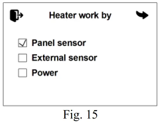
Air heater operating mode set– tings (Fig. 15):
Panel sensor – the set-point temperature of the temperature sensor located in the control panel is used for operation.
External sensor – the set-point temperature of an external temperature sensor is used for operation. Power – the power set-point is used for operation Operation time settings (Fig. 16).
Days – number of days;
Hours – number of hours;
Minutes – number of minutes;
Unlimited – no time limit.
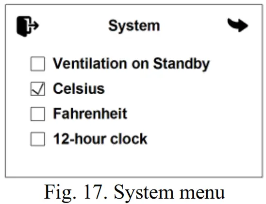
In the system menu (Fig. 17), you can switch between the units of temperature measurement: Celsius °C or Fahrenheit °F; select the 12-hour time format.
 Ventilation on Standby – when the heater switches to standby mode, the blower will continue to run in ventilation mode. System information window (Fig. 18) shows the software version of the control panel and the control unit of the product. It also displays the total number of hours the product has worked.
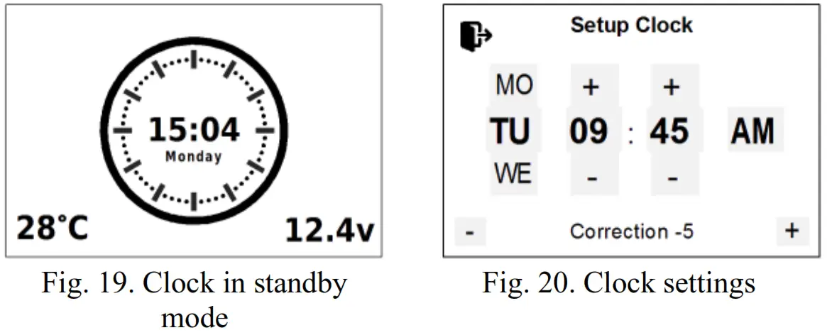
Date and time settings
To set the current time and day of the week, long tap on the current time in the corner of the screen. The time is set by tapping the “+” and “-”. At the bottom of the screen, you will find the Clock correction setting. Under the influence of low temperatures, the accuracy of the clock may vary. If necessary, the correction value is set between -720 and +720 sec. per day. The default correction time is . Tap to exit.
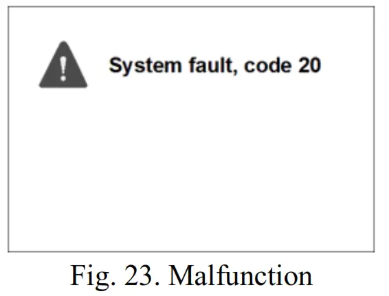
Malfunctions
Malfunctions that occur during heater operation are coded and au- tomatically displayed on the control panel display (Fig. 23). To reset a malfunction, tap the centre of the screen. Heater malfunction codes are given in Table 1.
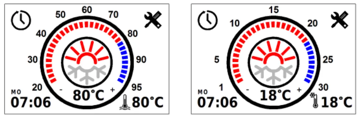 Fig. 1. The main screen of a liquid heater and an air heater After the product has been started up, the countdown of the oper- ation time in minutes (Fig. 2) will begin at the bottom left of the screen. Switching between operation time and current time is done by short tapping on the operating time.
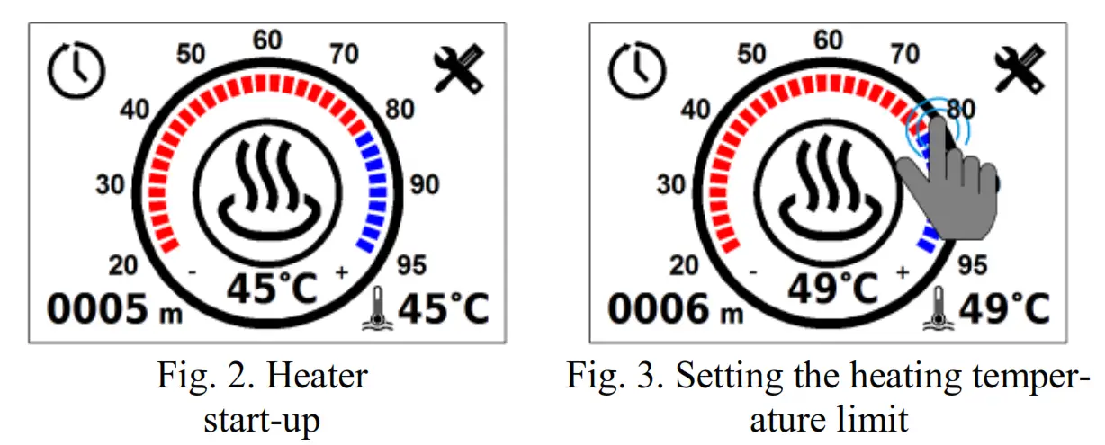 To shut the product down (Fig. 4), tap the centre of the screen or press mechanically. After the shut-down, the control panel switches to the main screen (Fig.1). When the control panel remains idle, it switches to standby mode to reduce the power consumption (Fig. 5).
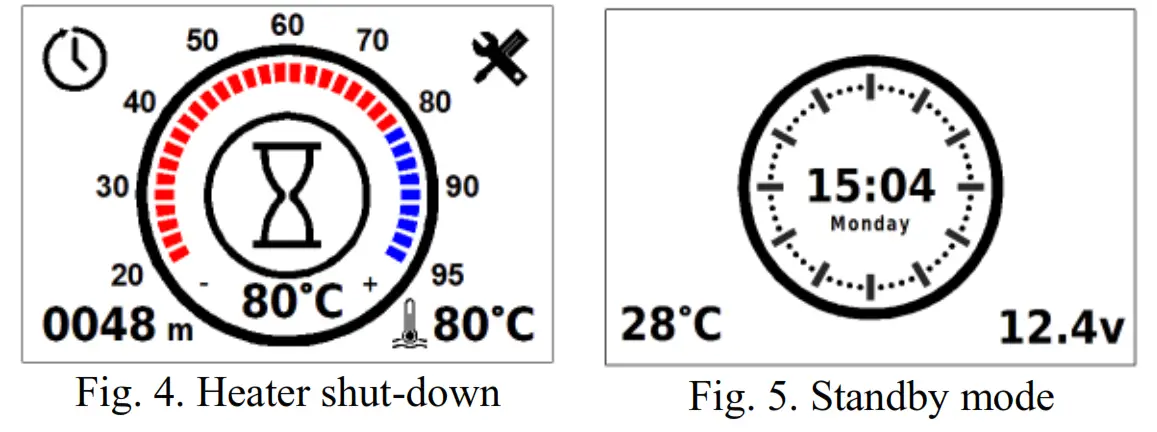
 Do not reset timers – the timer will not switch off after triggering.
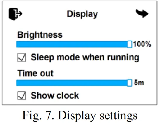 Sleep mode when running – turn the screen off while the product is in operation. To return from sleep mode, press or tap the screen. The time after which the remote control enters sleep mode can be adjusted from 30 sec, to 5 min. Show clock – display the current time and day of the week while the control panel is in sleep mode (only when the product is running).
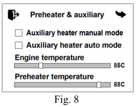 Auxiliary heater auto mode – automatic auxiliary heater mode. If the heater is switched off, it will start automatically after the engine is started. When the engine is stopped, the heater will switch off automatically. If the heater is switched on, it will automatically switch to the auxiliary heater mode when the engine is started.
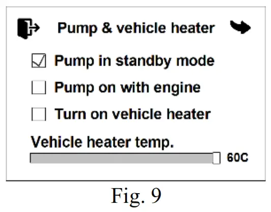 Pump on with engine – setting of starting the pump when the engine is started. The pump supplied with the heater can be used for additional circulation of the working liquid while the vehicle’s engine is running. The pump starts automatically when the engine is started and switches off when the engine is stopped.
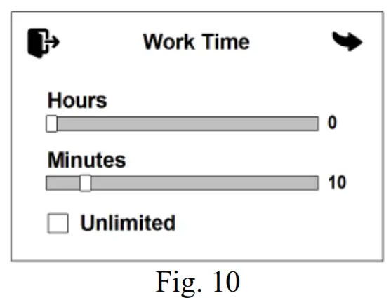 In the system settings (Fig. 11), you can switch between the units of temperature measurement: Celsius °C or Fahrenheit °F; select the 12-hour time format.
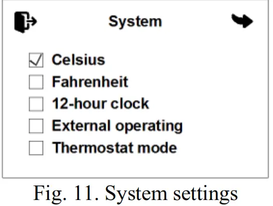 (Flow 5, Flow 6, Flow 10 only) using an external control channel (provided the heater is connected to the control channel). For the Flow 14 heater, this setting is not displayed and is enabled by default.
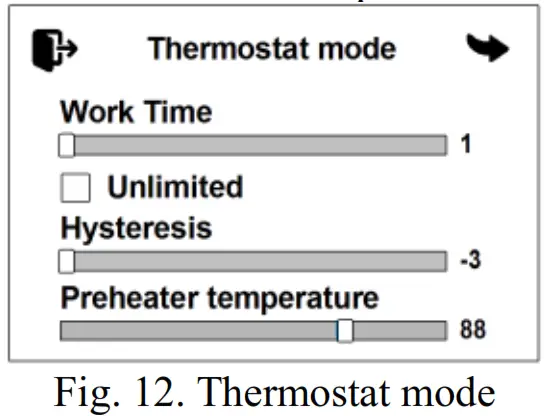 Preheater temperature – set-point for the heating medium temperature (60 to 95 °C).
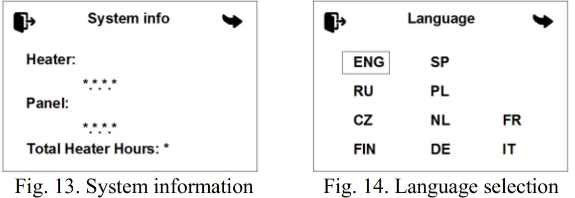
 Power – the power set-point is used for operation Operation time settings (Fig. 16).
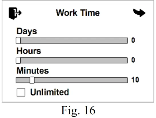
 Ventilation on Standby – when the heater switches to standby mode, the blower will continue to run in ventilation mode. System information window (Fig. 18) shows the software version of the control panel and the control unit of the product. It also displays the total number of hours the product has worked.
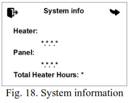
![]() ATTENTION
ATTENTION
Maintenance and repair should only be performed by trained, qualified personnel!
Malfunction codes
For the interpretation of the malfunction codes for the Flow 5, Flow 6, Flow 10 liquid heaters, see Table 1.
Table 1
| Code | Fault description | Comment. Fault elimination |
| 01 | Overheating of the heat exchanger. Check the air pipes for block- age. Check the tem- perature sensor. | 1. Check the entire fluid circuit. 2. Check the pump and replace if neces- sary. 3. Check the temperature sensor and the overheating sensor; replace if necessary. 4. Check the quality of the coolant, which must be used depending on the ambient temperature. |
| 02 | Overheating of the heat exchanger. Check the water hoses for blockage. Air in the water circuit. Wrong water flow direction | |
| 03 | Overheating sensor fault. Call service cen- ter | Replace the sensor assembly. |
| 04 | Coolant temperature sensor fault. Call ser- vice center | |
| 05 | Flame sensor fault. Call service center | Check the connection wires. Check the resistance between the indicator termi- nals, which should not exceed 10 ohms. Replace the flame indicator in the event of a malfunction. |
| 06 | Intake air temperature sensor fault. Call ser- vice center | Replace the heater control unit. |
| 09 | Glow plug failure. Call service center | Check the glow plug and replace if nec- essary. |
| 10 | Fan motor rpm mis- match. Call service center | Check the wiring of the electric motor. Repair the malfunction and replace the blower, if necessary. |
| 12 | Overvoltage. Check the battery voltage | This defect can occur when the heater is switched on while the car engine is run- ning. The cause may be a faulty voltage regulator in the car. |
| Code | Fault description | Comment. Fault elimination |
| 13 | No ignition 2 times. Check the fuel supply system and glow plug screen | If the permissible number of start at- tempts has been done, check the fuel amount and supply. Check the air intake, filter, and exhaust pipe. Check the glow plug. |
| 14 | Liquid pump short cir- cuit. Check the liquid pump wiring harness for short/open circuit | Check the circulation pump wiring for short circuits and open circuits, check the pump, and replace if necessary. |
| 15 | Undervoltage. Check the battery, fuses and wiring harness | Check the voltage at the heater con- nector. Check the battery, vehicle volt- age regulator, and power supply wiring. |
| 16 | Ventilation time ex- ceeded. Check the air pipes and exhaust/in- take pipes for block- age | The flame sensor has not cooled down sufficiently during purging. Check the air intake, filter, and exhaust pipe. Check the flame sensor and replace if neces- sary. |
| 17 | Fuel pump short cir- cuit. Check the fuel pump wiring harness for short/open circuit | Check the fuel pump wiring for short cir- cuits and replace if necessary. |
| 20 | No communication between the control unit and the control panel. Check the power supply, con- nectors and fuses | Check the connection cables and con- nectors. The control panel is not receiving data from the control unit. |
| 22 | Fuel pump short cir- cuit. Check the fuel pump wiring harness for short/open circuit | Check the fuel pump wiring for open cir- cuits and replace if necessary. |
| 24 | Rapid coolant temper- ature rise. Check the liquid pump and cool- ant circulation circuit | Possible overheating in the area of one of the temperature sensors due to poor cool- ant circulation. |
| 25 | The coolant heats up too quickly. Air in the coolant circle. Check | Check the entire fluid circuit. |
| Code | Fault description | Comment. Fault elimination |
| the coolant level, cool- ant flow direction | In 1 operating cycle, the heater has reached standby mode three times in less than 6 min. | |
| 26 | Fan motor overload. Check the fan blades for jamming | Check the blower fan. The blower fan impellers could be rubbing against the heater casing as a result of misalignment of the mounting. |
| 27 | Fan motor doesn`t ro- tate. Check the fan blades for jamming | Check the wiring, blower, and control unit; replace if necessary. |
| 28 | Fan motor itself rota- tion. Call service cen- ter | Check the wiring, blower, and control unit; replace if necessary. |
| 29 | Repetitive flame inter- ruption. Check the fuel supply system and glow plug screen | Check the fuel system. Check tightness of fuel line clamps, tightness of the fuel line, tightness of the fitting on the fuel pump, and fuel pump capacity. |
| 30 | No communication between the control unit and the control panel. Check the con- trol panel wiring har- ness | Check the connection cables and con- nectors. The control unit is not receiving data from the control panel. |
| 37 | Heater is blocked. Call service center* | Contact the service centre to unlock the heater. |
- * ATTENTION! If error #13 is repeated three times in a row during heater start-up, the heater will be locked out. This lockout is intended to prevent excess fuel from entering the combustion chamber. In the event of lockout, code 37 will be displayed on the control panel.
The malfunction codes for AIR air heaters are shown in Table 2.
Table 2
| Code | Fault description | Comment. Fault elimination |
| 1 | Overheating at the upper inlet tempera- ture limit | Check heater inlet and outlet connection for free air intake and exhaust. Check combustion air supply system and gas-escape line. Repeat the start-up to cool down the heater. |
| 2 | Possible overheating (based on standby time) | |
| 5 | Flame sensor fault. Call service center | Check the flame sensor in the heat ex- changer; replace if necessary. |
| 6 | Intake air tempera- ture sensor fault. Call service center | Replace the control unit. |
| 7 | Breakdown of the heat exchanger tem- perature sensor cir- cuit. | Check the temperature sensor circuit for open circuits. Only for air heaters AIR 4D, AIR 8D |
| 9 | Glow plug failure. Call service center | Check the glow plug; replace if necessary. |
| 10 | Fan motor rpm mis- match. Call service center | Check the blower motor wiring and re- place the blower if necessary. |
| 11 | Breakdown of the in- put air temperature sensor circuit. | Check the temperature sensor circuit and replace if necessary. Only for air heaters AIR 8D, AIR 9D |
| 12 | Overvoltage. Check the battery voltage | Check the battery, voltage regulator, and power supply wiring The voltage between pins 1 and 2 of the power connector must not exceed 30 V (for a 12 V product, must not exceed 16 V). |
| 13 | No ignition 2 times. Check the fuel supply system and glow plug screen | Check the fuel supply (inspect the fuel line). Check the combustion air supply system and the exhaust line. |
| Code | Fault description | Comment. Fault elimination |
| 15 | Undervoltage. Check the battery, fuses and wiring harness | Check the battery, voltage regulator, and power supply wiring The voltage between pins 1 and 2 of the power connector must be at least 20 V (for a 12 V product, at least 10 V). |
| 16 | The ventilation time is exceeded. | Check the air intake and the exhaust pipe. If clogged, remove any foreign particles. |
| 17 | Fuel pump short cir- cuit. Check the fuel pump wiring harness for short/open circuit | Check the fuel pump wiring for short cir- cuits and open circuits. |
| 20 | No communication between the control unit and the control panel. Check the power supply, con- nectors and fuses | Check the connection cables and connect- ors. The control panel is not receiving data from the control unit. |
| 27 | Fan motor doesn`t ro- tate. Check the fan blades for jamming | Check the connectors and harnesses lead- ing to the motor board and control unit. |
| 28 | Fan motor itself rota- tion. Call service cen- ter | Replace the blower fan. |
| 29 | Repetitive flame in- terruption. Check the fuel supply system and glow plug screen | Check the fuel supply (inspect the fuel line). Check combustion air supply system and gas-escape line. |
| 31 | Overheating inside the heater in the area of the temperature sensor at the heated air outlet. | Check heater inlet and outlet connection for free air intake and exhaust. |
| 32 | Faulty outlet air sen- sor. | Check the connection wires. The output signal and voltage are in a linear relation- ship to the temperature. Check the sensor and replace if necessary. |
| 33 | Heater is blocked. Call service center* | Contact the service centre to unlock the heater. |
* Attention! If the ‘Overheat’ error is repeated three times in a row during heater start-up or operation, the heater will be locked out. The lockout occurs upon overheating, irrespective of which sensors have registered an error. In the event of lockout, code 33 is displayed on the control panel. Contact the service centre to unlock the heater
| Code | Fault description | Comment. Fault elimination |
| 34 | Housing sensor in- correct installation | Only for air heaters AIR 8D. The housing sensor is installed in the wrong position and shows the wrong infor- mation. Only for air heaters AIR 8D, AIR 9D |
| 35 | Flame failure into the combustion chamber due to voltage drop. | Check the battery and wiring. (The voltage drop can be caused by the electric starter engaged for a longer time). |
| 36 | The flame indicator temperature exceeds normal. | Flame indicator malfunction (cracked housing). Stabiliser malfunction in the combustion chamber. Check the inlet and outlet connections. Only for air heaters AIR 8D, AIR 9D |
| 37 | Flame detector and outlet air sensors are connected incor- rectly. | Check the sensor connections. Connect as shown in the wiring diagram. Only for air heaters AIR 9D |
| 78 | Flame interruption during operation. Check the fuel supply system and glow plug screen | Displayed for user information. Check tightness of fuel line clamps, tight- ness of the fuel line, and tightness of the fitting on the fuel pump. |
For the interpretation of the malfunction codes for the Flow 14 pre-heater, see Table 3.
Table 3
| Code | Fault description | Comment. Fault elimination |
| 01 | Overheating of the heat exchanger. Check the air pipes for blockage. Check the temperature sen- sor. | 1 Check the entire fluid circuit. 2 Check the pump and replace if neces- sary. 3 Check the temperature sensor and the overheating sensor; replace if necessary. 4. Check the quality of the coolant, which must be used depending on the ambient temperature. |
| 02 | Overheating of the heat exchanger. Check the water hoses for blockage. Air in the water cir- cuit. Wrong water flow direction | |
| 03 | Overheating sensor fault. Call service center | Check the connection wires. The output signal and voltage are in a linear relation- ship to the temperature (0 °C corresponds to 2.73 V, and a rise of 1 °C in tempera- ture increases the output signal by 10 mV accordingly). Check the sensor and re- place if necessary. |
| 04 | Coolant temperature sensor fault. Call ser- vice center | |
| 05 | Flame sensor fault. Call service center | Check the connection wires. Check the resistance between the indicator termi- nals, which should not exceed 10 ohms. Replace the flame indicator in the event of a malfunction. |
| 06 | Intake air tempera- ture sensor fault. Call service center | Replace the heater control unit. |
| 09 | Glow plug failure. Call service center | Check the glow plug and replace if neces- sary. |
| Code | Fault description | Comment. Fault elimination |
| 10 | Fan motor rpm mis- match. Call service center | Check the wiring of the electric motor. Repair the malfunction and replace the blower, if necessary. |
| 12 | Overvoltage. Check the battery voltage | This defect can occur when the heater is switched on while the car engine is run- ning. The cause may be a faulty voltage regulator in the car. Check the voltage at the heater connector. |
| 13 | No ignition 2 times. Check the fuel supply system and glow plug screen | If the permissible number of start at- tempts has been done, check the fuel amount and supply. Check the air intake and exhaust pipe. Check the glow plug. Check the mesh and the Ø 1.5 mm open- ing in the combustion chamber plug con- nector for fouling, clean the Ø 1.5 mm opening if necessary, replace the mesh. |
| 14 | Liquid pump short circuit. Check the liq- uid pump wiring har- ness for short/open circuit | Check the pump wiring for short circuits and open circuits, check the pump, and re- place if necessary. |
| 15 | Undervoltage. Check the battery, fuses and wiring harness | Check the voltage at the heater connector. Check the battery, vehicle voltage regula- tor, and power supply wiring. |
| 16 | Ventilation time ex- ceeded. Check the air pipes and exhaust/in- take pipes for block- age | The flame sensor has not cooled down sufficiently during purging. Check the air intake and exhaust pipe. Check the flame sensor and replace if necessary. |
| 17 | Fuel pump short cir- cuit. Check the fuel pump wiring harness for short/open circuit | Check the fuel pump wiring for short cir- cuits and replace if necessary. |
| 20 | No communication between the control unit and the control panel. Check the | Check the connection cables and connect- ors. |
| Code | Fault description | Comment. Fault elimination |
| power supply, con- nectors and fuses | ||
| 27 | Fan motor doesn`t ro- tate. Check the fan blades for jamming | Check the wiring, electric motor, and con- trol unit; replace if necessary. |
| 28 | Fan motor itself rota- tion. Call service center | Check the wiring, electric motor, and con- trol unit; replace if necessary. |
| 29 | Repetitive flame in- terruption. Check the fuel supply system and glow plug screen | Check the fuel amount and supply. Check combustion air supply system and gas-es- cape line. If the heater is able to start, check the fuel pump and replace if neces- sary. |
| 78 | Flame interruption during operation. Check the fuel supply system and glow plug screen | Check the air intake, exhaust pipe, and fuel supply. Repair the malfunctions; re- place the fuel pump and the flame indica- tor if necessary. |
![]()


