Honeywell Y6H920RW5031 T6 Smart Thermostat Installation Guide
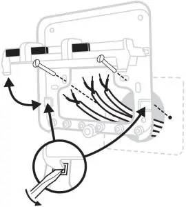
Turn OFF the power and remove the old thermostat
To ensure your safety, always make sure mains power is switched OFF before accessing wiring.
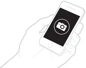
Before removing the old thermostat take a picture of the old thermostat’s wiring as reference then proceed to installation.
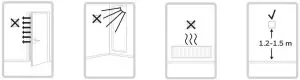
The T6 thermostat should not be placed near draughts, in direct sunlight or near heat sources. It should be at least 1.2 – 1.5 meters from the floor.
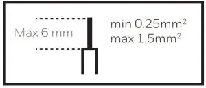
Maximum cable length between Receiver box and thermostat:
- 15m for 0.5mm² cable or 20m for 1.0mm² cable.
Prepare Receiver Box for installation
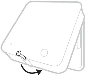
Before installation of the Receiver Box
Find a suitable location near to the boiler.
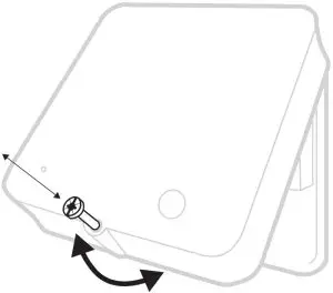
Loosen the front screw to remove cover or tighten it when the cover is back in place.
Needed during installation:
- Cable with 2 wires from the Receiver Box (R4H810A) to thermostat.
- Cable with 2 wires from the boiler to Receiver Box.
- The Receiver Box requires 230V power
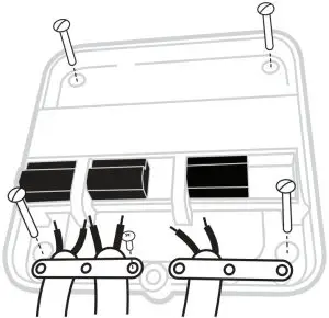
Install the Receiver Box
 Please refer to the wiring diagrams over the page
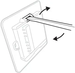
- Wall box or Rear Wiring Hinge open the terminal block flap to access the cables and wall box screw holes.


- Surface wiring
Use the cable clamps to secure the surface wiring.
- Replace the cover
Locate the hinges at the top of the cover and wall plate, close the cover and secure with the screw.
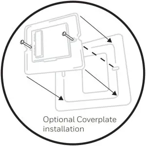
Install the T6 thermostat
Remember to use the same wires that you connected to the Receiver Box when connecting to the thermostat.
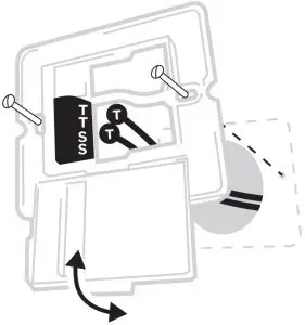
- Using a screwdriver open wallplate terminal cover to connect wires

- Connect 2 thermostat wires to the T and T terminals and close cover.

- Attach the thermostat to the wallplate when finished.

Complete installation
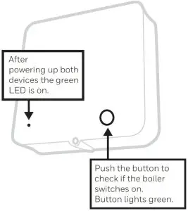
Turn ON mains power to the Heating Appliance and Receiver Box.
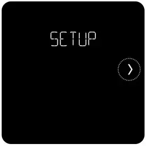
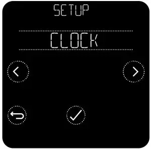
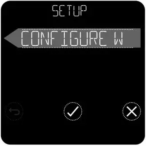
- After power up, SETUP is displayed on the thermostat’s screen.

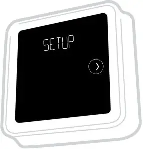
Set Up and configuration
- Touch
 to begin setting up the thermostat.
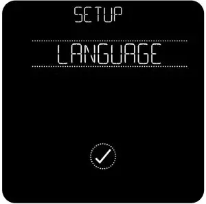
 - Select your language.

- Set the clock format, time and date.
- Touch
 to finalise setup. ( to setup using the App is currently unsupported)
Once setup is completed, if you need to change more settings go to the advanced menu. To access the advanced menu press ![]() for 5 seconds.
for 5 seconds.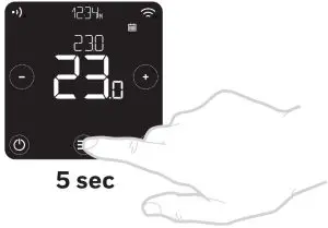
In the advanced menu the following settings can be adjusted:
| Menu Item | Default | Options |
| LANGUAGE | English | 0 = English, 1 = Français, 2 = Español 3 = Deutsch, 4 = Nederlands, 5 = Italiano |
| OPENTHERM | – | OpenTherm boiler data when available |
| CYCLE RATE | 6 | 3, 6, 9 or 12 |
| MINIMUM ON TIME | 1 minute | 1, 2, 3, 4 or 5 minutes |
| HEAT RANGE | Min = 5.0ºC Max = 35.0ºC | Min: 5ºC to 21ºC, Max: 21ºC to 35ºC |
| SCHEDULE OPTIONS | Daily | 1 = Daily schedule, 2 = 5+2 days schedule |
| EXTERNAL SENSOR | No sensor | 0 = No sensor, 1 = Room sensor |
| OPTIMISE | Opt. start OFF Opt. stop OFF | Opt. start: 0 = off, 1 = on, 2 = Delayed start Opt. stop: 0 = off, 1 = on |
| CLOCK | Format: 24h Time: –:– Date: 01/09/16 | Clock format: 1 = 12h, 2 = 24h Setup time and date |
| LOW LOAD CONTROL | ON | 0 = off, 1 = on |
| TEMPERATURE OFFSET | 0.0ºC | -1.5 ºC to 1.5ºC |
| RESET | – | Factory, schedule, WiFi and HomeKit reset |
| FAILSAFE | OFF | 0 = off, 1 = on |
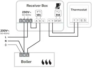
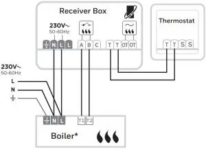
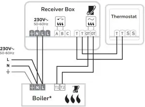
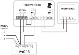
Wiring Diagrams
- Wiring for basic 230V boiler

- Wiring for Combi boiler

- Wiring for OpenTherm boiler
See boiler specifications for correct terminals
For other wiring diagrams visit
https://hwllhome.co/uk-wiring - Wiring for two-port zone valve


Need help? For assistance please visit: getconnected.honeywellhome.com
200 Berkshire Place,
Winnersh Triangle
Berkshire RG41 5RD
Phone: 0300 130 1299
Approvals
Hereby, Pittway Sarl declares that the radio equipment type T6H700RW is in
compliance with Directive 2014/53/EU. The full text of the EU declaration of
conformity is available at the following internet address: https://hwllhome.co/DoC
Wi-Fi (2.4GHz): Max Power 100mW, 2.4–2.458GHz
ErP: Class V (+3%), (EU) 811/2013
![]() Must be installed by a competent person!
Must be installed by a competent person!
Read these instructions carefully. Failure to follow these instructions
can damage the product or cause a hazardous condition.
WEEE Directive 2012/19/EC Waste Electrical and Electronic Equipment directive
![]() At the end of the product life dispose of the packaging and product in a corresponding recycling centre. Do not dispose of the unit with the usual domestic refuse. Do not burn the product.
At the end of the product life dispose of the packaging and product in a corresponding recycling centre. Do not dispose of the unit with the usual domestic refuse. Do not burn the product.


