V-TAC Innovative LED Lighting
![]()
TECHNICAL DATA:
| SKU | 8343 |
| Input Voltage | AC:220-240V,50/60Hz |
| Charging Time | 24 Hours |
| Emergency Power | 6-7W |
| Emergency Operation Time | 3 Hours |
| Charge and Recharge | 500 Times |
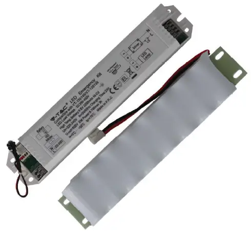
| Battery Type | Ni-Cd 9.6V 2200mAh |
| Ambient Temperature ta | 0-50°C |
| Compatible with | SKU: 20214 | 20215 SKU: 20216 | 20217 |
| Dimension | 212x40x30mm |
INTRODUCTION
Thank you for selecting and buying V-TAC product. V-TAC will serve you the best. Please read these instructions carefully before starting the installation and keep this manual handy for future reference. If you have any another query, please contact our dealer or local vendor from whom you have purchased the product. They are trained and ready to serve you at the best.
WARNING!
- Please make sure to turn off the power before starting the installation.
- Installation must be performed by a qualified electrician.
- The emergency kit is designed with a replaceable battery. If the battery no longer meets their rated duration of operation after corresponding recharge period the battery/emergency kit should be replaced by the manufacturer or his service agent or a similar qualified person in order to avoid a hazard.
CAUTION:
- Please make sure to switch off the power before starting the installation.
- Battery is in an empty state, please ensure to charge more than 36hours before using.
- Power connected but light does not work, please check whether the light is properly connected to the mains.
- Please strictly use the emergency kit according to the wiring diagram before connection and pay attention to reverse connection.
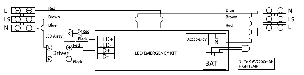
EMERGENCY WIRING DIAGRAM
STEP 1: Please make sure to switch off the power before starting the installation.
STEP 2: Open the side clips of waterproof fitting and open the diffuser as shown in the diagram.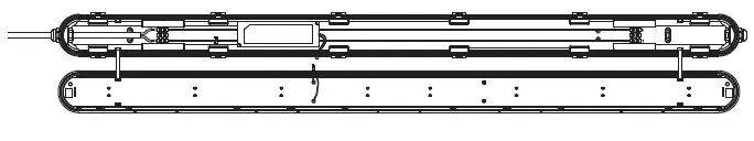 STEP 3: Remove the screws from the driver. Remove Brown wire from terminal L from both the ends of the waterproof fitting and reinstall the Brown wire to terminal LS on both the ends.
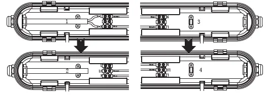 STEP 4: Install the Red wire on the terminal (L) from one end to the other end of the terminal block. Using the screws reinstall the driver on the fitting.
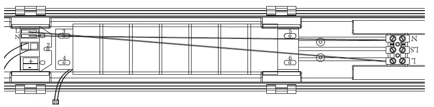
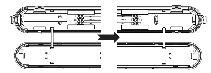 STEP 5: Install the iron plate(included) on the fitting using 3pcs screws (1,2,3 hole for 36W, 1,2,4 hole for 48W).
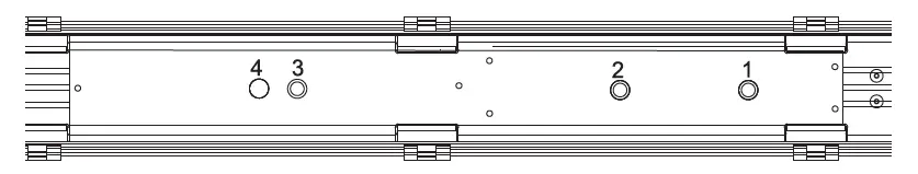
STEP 6: Fix the battery with 4pcs screws and the Emergency kit with 2pcs screws on the iron plate.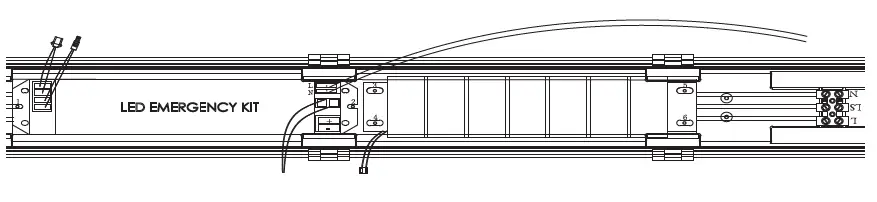
STEP 7: The wire L(Red) of the kit is connected to the main power L(live), the wire N(Blue) of the kit is connected to the main power N(Neutral).
STEP 8: Connect the driver plug to the Emergency kit as shown in the diagram.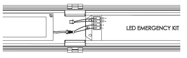
STEP 9: Connect the battery plug.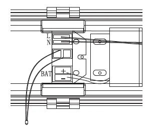
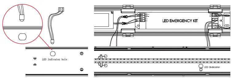
STEP 10: Fix the LED indicator on the holder and connect the LED plug to the Emergency kit as shown in the diargam.
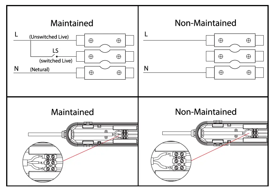
STEP 11: For Maintained OR Non-Maintained wiring please refer to the wiring diagram and power the waterproof fitting accordingly. Fix the diffuser on the waterproof fitting and close the side clips. Turn ON the power to test the light.![]()


