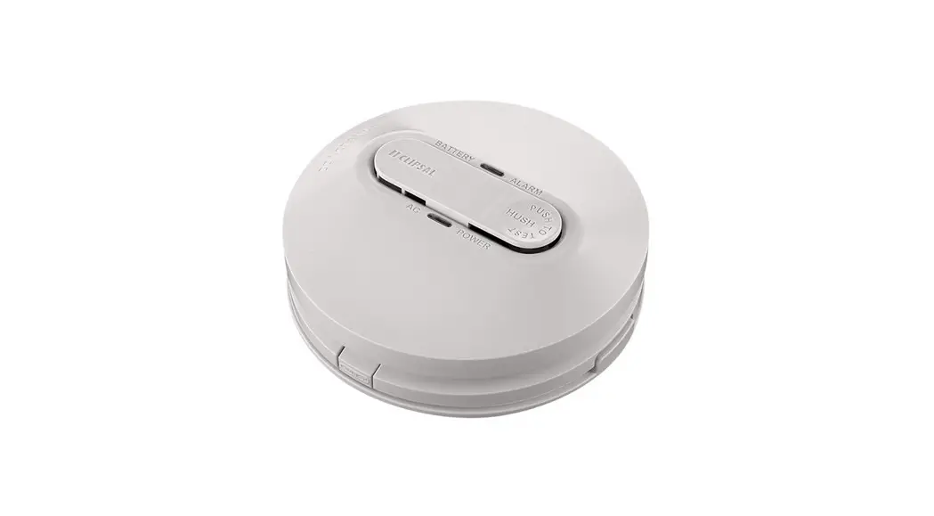
![]() 755PSMA4 Smoke Alarm Photo, Surface, 230v
755PSMA4 Smoke Alarm Photo, Surface, 230v
Instruction Manual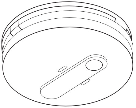
240 V a.c. Mains Power Photoelectric Smoke Alarm with 9 V d.c. Battery Backup
 More information is available
 https://download.schneider-electric.com/files?p_Doc_Ref=EAV8159103
Scan the QR code for more information about your Clipsal smoke alarm:
- What smoke alarms can and cannot do
- Developing and practising a plan of escape
- What to do if an alarm sounds.
Operating the smoke alarm ![]()
 Operating elements
 Installation location
Install more than 1 m away from air conditioner/heater vents and fans, electrical sources, appliances and fittings.
Example: Class 1a building![]() Smoke alarm
Smoke alarm![]() Recommended additional alarms (or as required by legislation)
Recommended additional alarms (or as required by legislation)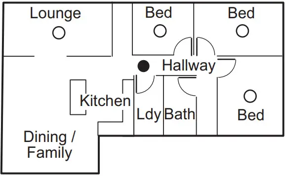
Do not install in garages, kitchens, bathrooms or any area with high levels of moisture, dirt or insects.
For garages: A heat alarm is more suitable as it is not affected by particulates.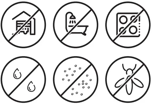
Example: Class 1b building![]() Smoke alarm
Smoke alarm![]() Smoke alarm with evacuation lighting
Smoke alarm with evacuation lighting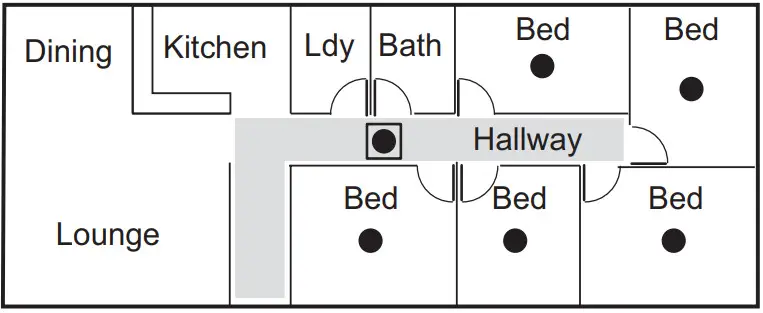
![]() Dead air space (do not install in these locations
Dead air space (do not install in these locations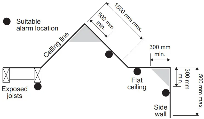 Storeys with bedrooms:
![]() Alarm in hallway connecting bedrooms
Alarm in hallway connecting bedrooms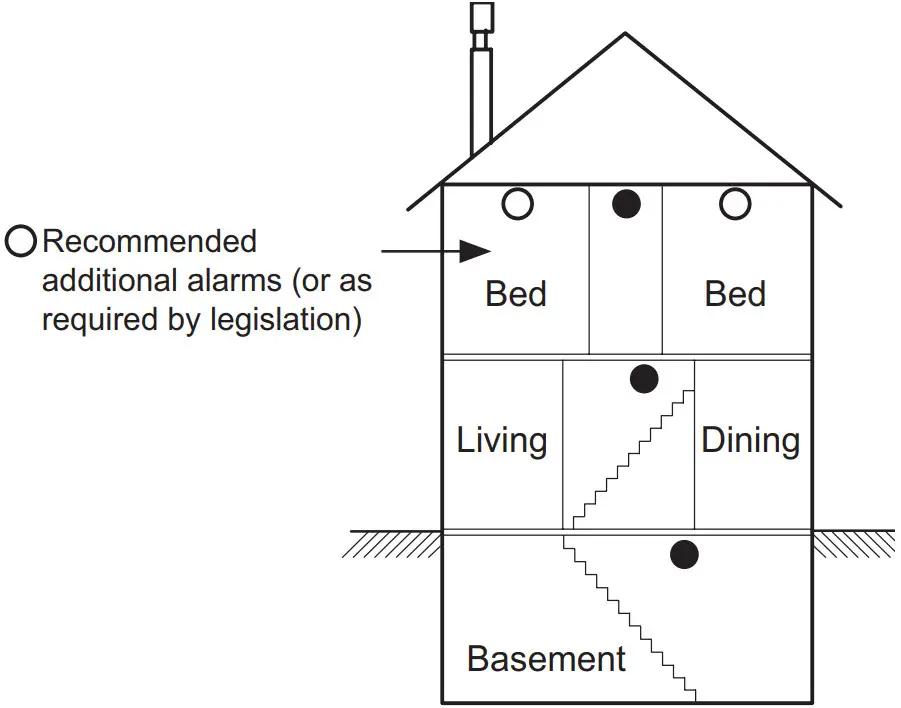
Storeys with no bedrooms:![]() Alarms located in the area of the stairway.
Alarms located in the area of the stairway.
 Installation
 Note: Ensure that the alarm base is mounted flat against the mounting surface.
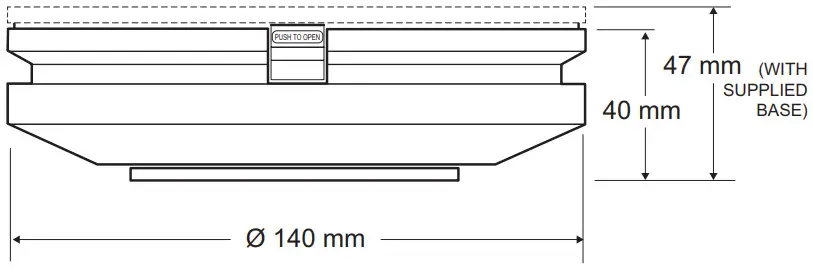
Single alarm
Terminal markings:
A: Active/Line
E-Loop: Earth or Loop
N: Neutral
I-Connect: Interconnect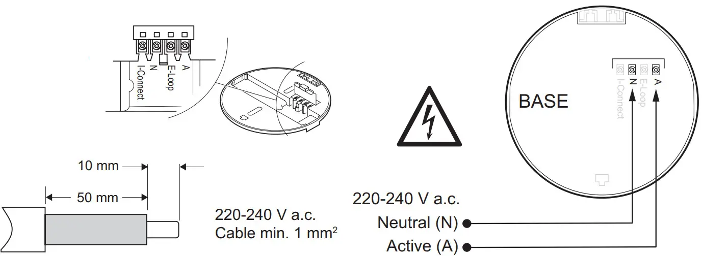
Interconnected alarms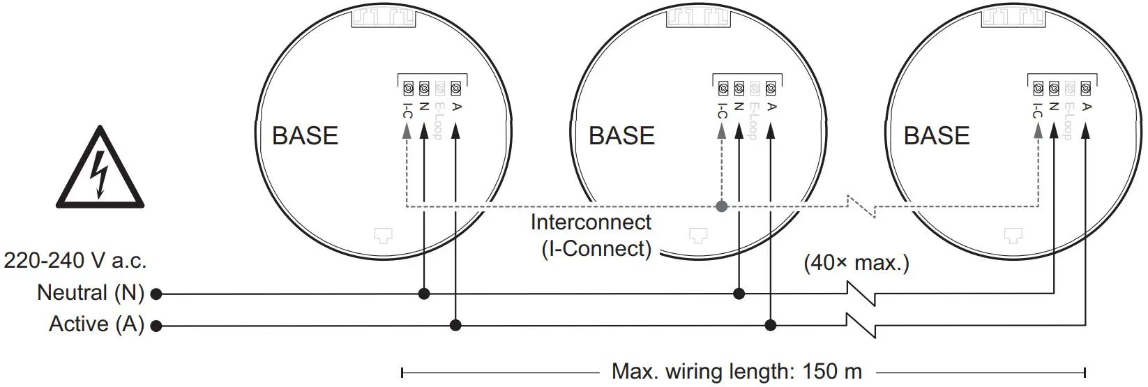
General information
 Leave these instructions with the occupant, to be retained for the life of the alarm.
- This smoke alarm must be installed by a licenced electrician.
- Do not remove dust cover until 24 hours after all construction has been completed. Construction dust and chemicals can cause contamination and false alarms.
- Important: Dust cover must be removed before smoke alarm will operate correctly.
For your safety![]()
![]() DANGER
DANGER
RISK OF ELECTRIC SHOCK, EXPLOSION OR ARC FLASH
- This product must only be installed and serviced by appropriately qualified and/or licenced electrical personnel.
- This product must only be used for the purposedescribed in these instructions and must be installed in accordance with the wiring rules and regulations in that location.
- Isolate the electrical supply before doing any work on this product.
- Ensure the product has been correctly installed and tested for safe operation before reconnecting the electrical supply.
Failure to follow these instructions will result in death or serious injury.![]() CAUTION
CAUTION
EQUIPMENT INSTALLATION HAZARD
- Ensure active and neutral from mains power are wired to the correct terminals.
- Ensure the green LED is ON when mains power is supplied.
- Ensure the red LED is not flashing quickly.
- Test each interconnected unit 1 by 1. Press and hold the Test button until second burst of 3 beeps has finished. If any unit fails to alarm, check all wiring and connections.
Failure to follow these instructions may result ininjury or equipment damage.
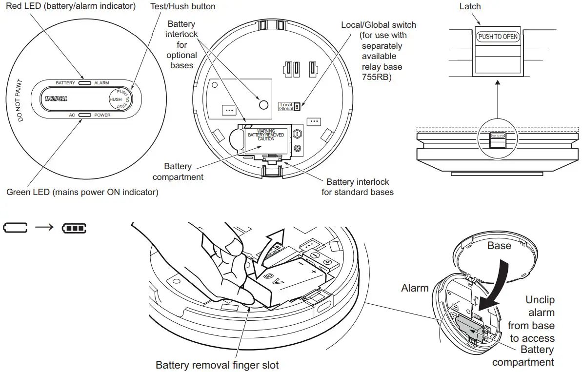
Operating elements ![]()
Installing/replacing the backup battery![]()
- The backup power to the smoke alarm is supplied by a 9 V d.c. carbon zinc or alkaline battery. The battery should last at least one year under normal operating conditions.
- An audible beep every 40 seconds indicates the battery needs to be replaced. It is recommended to replace the battery annually on a memorable day using the calendar reminder stickers provided.
- Recommended batteries include: Energizer 522, Duracell MN1604, Eveready A522 or 1222, GP 1604A.
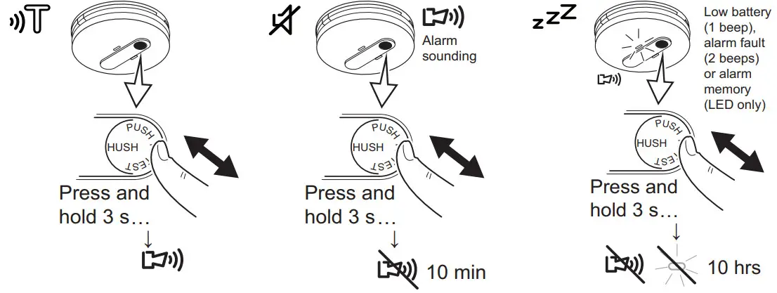
- To snooze a low battery beep for 10 hours, press the Test/Hush button for 3 seconds.
Choosing the installation location ![]()
![]() Prior to installing, ensure there are no obstructions in ceiling mounting locations, such as pipes or cables.
Prior to installing, ensure there are no obstructions in ceiling mounting locations, such as pipes or cables.
NOTICE
EQUIPMENT INSTALLATION COMPLIANCE
This smoke alarm must be installed in accordance with the National Construction Code and any local state legislation requirements.
Failure to follow these instructions may result in a non-compliant installation.
Installing the smoke alarm ![]()
- Only install smoke alarm indoors in a stand-alone or interconnected set up (see Interconnecting smoke alarms).
- Use minimum cable width 1 mm for all wiring, including interconnect wiring where used.
- Do not remove the dust cover until you are ready to test the unit. See

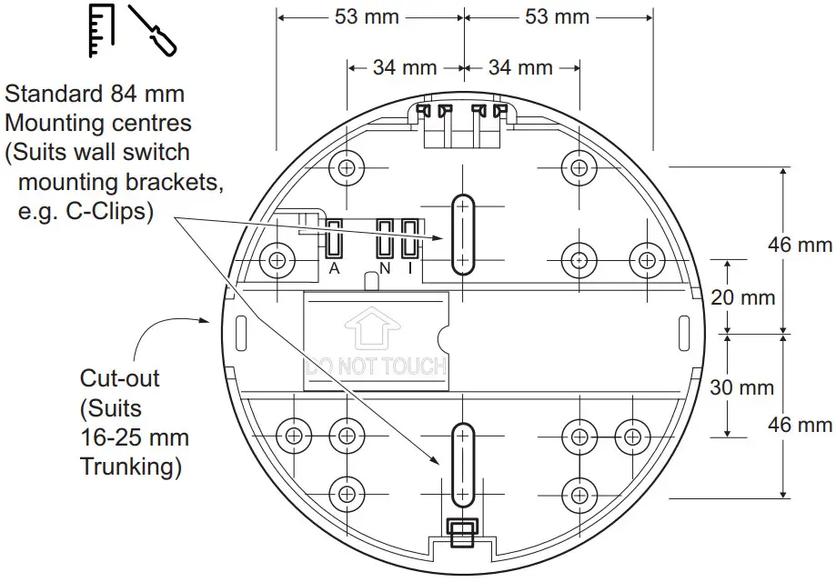
Mounting the smoke alarm![]()
Connecting the smoke alarm![]() (see Single alarm)
(see Single alarm)
Interconnecting smoke alarms![]() (see Interconnected alarms)
(see Interconnected alarms)![]() CAUTION
CAUTION
EQUIPMENT INSTALLATION HAZARD
- All interconnected smoke alarms must be supplied from the same circuit.
- A common Neutral must be used for the Interconnect to operate.
- DO NOT connect the Interconnect wire to Active or Neutral.
- Maximum of 40 interconnected smoke alarms.
- Only Clipsal smoke alarms are compatible forinterconnection with this alarm.
Failure to follow these instructions may result in injury or equipment damage.![]() Maximum wire length between first and last alarm is 150 m.
Maximum wire length between first and last alarm is 150 m.
Wireless interconnection
An optional wireless base (Catalogue No. 755RFB2) may be purchased separately if wired interconnection is not possible.![]() A maximum of 40 smoke alarms can be interconnected using wireless bases.
A maximum of 40 smoke alarms can be interconnected using wireless bases.
Operating the smoke alarm 
Testing the smoke alarm![]()
![]() CAUTION
CAUTION
DO NOT USE OPEN FLAME
Never use an open flame of any type to test your alarm.
Failure to follow this instruction may result in injury or equipment damage.
- Test the smoke alarm once per month to ensure proper operation.
- If no alarm sounds, check the battery orientation or replace the battery (see
 ). If the battery is new, installed in the correct orientation and the alarm still doesn’t sound, replace the smoke alarm.
 - If the smoke alarm is installed in a mobile home, test weekly and before every journey.
- IMPORTANT: If premises are unoccupied for a more than a few days, a battery test must be undertaken upon return. If the low battery warning sounds, replace with new battery and test again.
- Check that all interconnected smoke alarms operate during the test.
Interconnected smoke alarms
- Test each alarm in an interconnected group.
- For each alarm test, ensure that all interconnected alarms operate.
Silencing the smoke alarm (Hush feature)![]()
- When the Test/Hush button is pressed during an alarm event, the smoke alarm is not sensitive to smoke for 10 minutes, after which the alarm resumes normal operation. During this hush time, the red LED flashes once every 8 seconds.
- Wait 10 minutes before performing any additional testing to avoid any abnormal alarm responses.
Snoozing low battery, fault and alarm memory indications![]()
Low battery![]() When the backup battery gets low, the red LED flashes once every 40 seconds, together with a beep sound. You can snooze the low battery indication for 10 hours by pressing the Test/Hush button for 3 seconds.
When the backup battery gets low, the red LED flashes once every 40 seconds, together with a beep sound. You can snooze the low battery indication for 10 hours by pressing the Test/Hush button for 3 seconds.
Replace the backup battery as soon as possible.
Alarm fault![]() When an alarm fault is detected, the red LED flashes once every 40 seconds, together with 2 beeps. You can snooze the alarm faultindication for 10 hours by pressing the Test/Hush button for 3 seconds.
When an alarm fault is detected, the red LED flashes once every 40 seconds, together with 2 beeps. You can snooze the alarm faultindication for 10 hours by pressing the Test/Hush button for 3 seconds.
Alarm memory![]() In an interconnected alarm group, the red LED on the triggered alarm flashes once every2 seconds for 72 hours after the alarm beeping has stopped, so that you can identify the unit as the alarm that was triggered. Press the Test/Hush button for 3 seconds to snooze the flashing LED for 10 hours. The snooze function for the alarm memory can be repeated as often as desired up to the 72 hour limit.
In an interconnected alarm group, the red LED on the triggered alarm flashes once every2 seconds for 72 hours after the alarm beeping has stopped, so that you can identify the unit as the alarm that was triggered. Press the Test/Hush button for 3 seconds to snooze the flashing LED for 10 hours. The snooze function for the alarm memory can be repeated as often as desired up to the 72 hour limit.
LED and sound indications
| Operating mode | Red LED | Sound | Duration | |
| Normal mode / Standby mode | 1 flash every 40 s | OFF | — | |
| ALARM MODE | Local alarm | 1 flash every 1 s | Continuous siren | — |
| Interconnected alarm | OFF | Continuous siren | — | |
| Test mode | 1 flash every 1 s | Siren (3 s) | ||
| Hush mode | 1 flash every 8 s | OFF | 10 min | |
| ALARM MEMORY (triggered alarm only) | Normal | 1 flash every 2 s after alarm stops | OFF | Total 72 hrs |
| Hushed during alarm | 1 flash every 2 s after Hush started | OFF | Total 72 hrs | |
| Snooze | See Snooze Mode | |||
| Low battery mode | 1 flash every 40 s | 1 beep every 40 s | Until backup battery is replaced | |
| Fault mode | 2 flashes every 40 s | 2 beeps every 40 s | Until fault has been cleared | |
| SNOOZE MODE | Low battery | 1 flash every 24 s | OFF | 10 hrs |
| Fault | 1 flash every 24 s | OFF | 10 hrs | |
| Alarm memory | 1 flash every 40 s | OFF | 10 hrs | |
| Green LED | |||
| Mains power ON | ON | — | — |
Troubleshooting
| Problem | Cause and Resolution | |
| ALERTS AND SILENCING | Alarm sounds and the red LED is blinking rapidly | Smoke has activated the smoke alarm. Vacate the building immediately and call the Fire and Emergency Services. See False Alarm section. |
| Alarm sounds but the red LED is OFF | Smoke has activated an interconnected alarm, located somewhere else in the building. Vacate the building immediately and call the Fire and Emergency Services. See False alarm section. | |
| Smoke alarm is sounding, it stops when Test/Hush is pressed | Hush or silence feature has been activated for 10 minutes providing the smoke density does not increase. Ensure you are safe and have put out the source of the smoke. See False alarm section. | |
| Red LED is flashing every 2 seconds | Alarm memory has been activated, indicating that this alarm was the triggered alarm in the group. LED stops flashing after 72 hours. Press Test/Hush to snooze the LED indication for 10 hours. | |
| Smoke alarm is sounding and does not stop when Test/ Hush is pressed | Smoke density is too high for the Hush or Silence feature to activate. Vacate the building immediately and call the Fire and Emergency Services. See False alarm section. | |
| When Test/Hush button is pressed for three seconds alarm sounds briefly | The smoke alarm horn is indicating that all electronic circuitry, horn and battery are working. Normal test condition. Test regularly to ensure proper operation. | |
| When Test/Hush button is pressed for three seconds alarm does not sounds | The smoke alarm may not be operating correctly. Check and ensure that the green LED is ON and the red LED flashes once every 40 seconds. If the problem persists contact an electrician for replacement. | |
| BEEPING | One audible beep every 40 seconds | Low battery warning. Replace the 9 V d.c. battery with a new one. |
| Two audible beeps every 40 seconds | The smoke alarm may not be operating correctly. Clean smoke alarm according to the Maintenance, Repairs and Service section. If problem persists, contact an electrician for replacement. | |
| POWER AND BATTERY | Smoke alarm body will not close on the base | 9 V d.c. backup battery is not installed. Insert a new 9 V d.c. battery. |
| Red LED not flashing every 40 seconds | Battery may be reversed, not present or completely flat. Check and re-install or replace the battery. | |
| Red LED flashes very quickly (3 times per second) | Neutral connection is bad or wiring is wrong. Check wiring and connection of smoke alarms with flashing red LED and rectify wiring issue immediately. | |
| Green LED off | Mains power may be disconnected. Check mains power ON. Main circuit breaker may have tripped. Wiring could be wrong. | |
False Alarm
In the event of a false alarm in an interconnected group, it is important to identify the triggering alarm(s). These alarms may need to be cleaned, serviced or replaced if necessary.
When alarms are sounding without any smoke present:
- Identify which smoke alarm(s) are being triggered – Look for the alarm(s) with sound and red LED flashing.
- Unclip all identified smoke alarms. Any remaining interconnected alarms will stop alarming in 1 minute.
- If the alarming stops before you have identified the alarms that are being triggered, look for any alarms with the red LED flashing once every 2 seconds. This flashing can be snoozed for 10 hours by pressing the Test/Hush button for 3 seconds. The snooze function can be repeated as often as desired up to the 72 hour limit.
- Clean affected smoke alarms in accordance with the Maintenance, Repairs and Service section.
- Re-install and test all the smoke alarms.
If all of the above fails, contact a licenced electrician for replacement.
Maintenance, Repairs and Service
Maintenance
It is recommended that the smoke alarm is inspected monthly to ensure it is free from dirt, dust and insects. The alarm can be vacuumed or brushed with a soft brush to remove dust, dirt or kitchen grease that has accumulated. Apply a small amount of insect surface spray to a cloth and wipe around alarm/s every 3-6 months to mitigate insect ingress.
ALWAYS TEST THE SMOKE ALARM AFTER CLEANING
Repairs and Service
NOTICE
EQUIPMENT MAINTENANCE INSTRUCTIONS
- Test this smoke alarm regularly to ensure the unit is functional and that the battery is in good condition.
- Replace the backup battery every year.
- Replace the smoke alarm 10 years after date of manufacture.
- Do not open the smoke alarm casing or repair the smoke alarm yourself. The only user-serviceable part is the replaceable backup battery. There are no other user-serviceable parts inside.
Failure to follow these instructions may result in equipment malfunction or failure.
Disposal
As the smoke alarm does not contain any radioactive material, disposal with normal rubbish is permitted in Australia and New Zealand.
Before disposal, move the battery disconnect switch to the disconnect position. This will prevent the low battery warning beep when the battery eventually discharges.
Technical data
| Main Power Source | 220–240 V a.c., 50 Hz |
| Secondary Power Source | 9 V d.c. carbon zinc or alkaline battery |
| Operating Current | ≤40 mA |
| Battery Life | 1 year |
| Sensing Type | Photoelectric. This alarm contains NO radioactive material. |
| Operating Temperature | 0 °C to 45 °C |
| Ambient Humidity | 5% to 95% |
| Interconnecting | Wired: 40 alarms over 150 metres maximum Wireless: 40 alarms maximum |
| Terminal Provisions | Active, Neutral, Loop and Interconnect terminals, each accommodates 2 × 1.5 mm2 |
| Horn Level | 85 dB at three metres minimum |
| Approvals | Activfire SAI Global RCM |
| Complies with | AS 3786: 2014, AS/NZS 60065 and AS/NZS 60950.1 |
![]() It is recommended to dispose of this device at an authorised electronic waste collection point. Professional recycling protects people and the environment against potential negative effects.
It is recommended to dispose of this device at an authorised electronic waste collection point. Professional recycling protects people and the environment against potential negative effects.
Trademarks and certifications
Schneider Electric acknowledges that the Australian Standard Certified Product logo is a trademark of SAI Global, and that the Activfire Certified logo is a trademark of CSIRO.![]()
Warranty
We warrant this product to be free from defects in materials and workmanship for a period of 5 (five) years from the date of installation.
Customer care
If you have technical questions, please contact the Customer Care Centre in your country.
Australia
Schneider Electric (Australia) Pty Ltd
33-37 Port Wakefield Road, Gepps Cross SA 5094
Customer Care Australia: 13 73 28
e: [email protected]
www.schneider-electric.com.au
New Zealand
Schneider Electric (NZ) Ltd
Building 6, 60 Highbrook Drive, East Tamaki,
Auckland, 2013
After hours service: 0800 735 4357 (NZ only)
Customer Care NZ: 0800 652 999
e: [email protected]
www.schneider-electric.com
![]() QGH8213701_02
QGH8213701_02
References
 Electric | The Largest Consumer Energy & Renewables Platform
-
Choose Energy® | Switch Providers & Save | Enroll Online
 Schneider Electric Global | Global Specialist in Energy Management and Automation
-
Schneider Electric Global | Global Specialist in Energy Management and Automation
-
Schneider Electric Australia | Global Specialist in Energy Management and Automation


