
LG U+ [email protected]
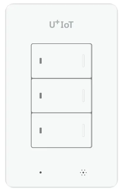
Smart Switch
SKU: SSD-305


Quickstart
This is a
secure
On/Off Power Switch
for
South Korea.
Please make sure the internal battery is fully charged.
To add this device to your network execute the following action:
After mounting the UZB controller to your PC and running the PC Controller program, click the Add button in the PC Controller program. Press the button on the Smart Power Strip for more than five seconds after you plug the Smart Power Strip into a power outlet and it will include to the network controller, while flashing the red button on the LED Smart Power Strip.
Please refer to the
Manufacturers Manual for more information.
Important safety information
Please read this manual carefully. Failure to follow the recommendations in this manual may be dangerous or may violate the law.
The manufacturer, importer, distributor and seller shall not be liable for any loss or damage resulting from failure to comply with the instructions in this manual or any other material.
Use this equipment only for its intended purpose. Follow the disposal instructions.
Do not dispose of electronic equipment or batteries in a fire or near open heat sources.
What is Z-Wave?
Z-Wave is the international wireless protocol for communication in the Smart Home. This
device is suited for use in the region mentioned in the Quickstart section.

Z-Wave ensures a reliable communication by reconfirming every message (two-way
communication) and every mains powered node can act as a repeater for other nodes
(meshed network) in case the receiver is not in direct wireless range of the
transmitter.
This device and every other certified Z-Wave device can be used together with any other
certified Z-Wave device regardless of brand and origin as long as both are suited for the
same frequency range.
If a device supports secure communication it will communicate with other devices
secure as long as this device provides the same or a higher level of security.
Otherwise it will automatically turn into a lower level of security to maintain
backward compatibility.
For more information about Z-Wave technology, devices, white papers etc. please refer
to www.z-wave.info.
Product Description
This device is a smart light switch using 1 wire AC line.You can control the light from the remote.Input AC power : 220V
Prepare for Installation / Reset
Please read the user manual before installing the product.
In order to include (add) a Z-Wave device to a network it must be in factory default
state. Please make sure to reset the device into factory default. You can do this by
performing an Exclusion operation as described below in the manual. Every Z-Wave
controller is able to perform this operation however it is recommended to use the primary
controller of the previous network to make sure the very device is excluded properly
from this network.
Reset to factory default
This device also allows to be reset without any involvement of a Z-Wave controller. This
procedure should only be used when the primary controller is inoperable.
With the device powered, press and hold the third button for 10 seconds.he LED of the button will flash red after 5 seconds, it will turn green, then it will flash red again. Then release the button.After a few moments, the entire LED is blinking and the green LED stops flashing.Please use the procedure only in the event thant the network primary controller is missing or otherwise inoperable.
Inclusion/Exclusion
On factory default the device does not belong to any Z-Wave network. The device needs
to be added to an existing wireless network to communicate with the devices of this network.
This process is called Inclusion.
Devices can also be removed from a network. This process is called Exclusion.
Both processes are initiated by the primary controller of the Z-Wave network. This
controller is turned into exclusion respective inclusion mode. Inclusion and Exclusion is
then performed doing a special manual action right on the device.
Inclusion
After mounting the UZB controller to your PC and running the PC Controller program, click the Add button in the PC Controller program. Press the button on the Smart Power Strip for more than five seconds after you plug the Smart Power Strip into a power outlet and it will include to the network controller, while flashing the red button on the LED Smart Power Strip.
Exclusion
After mounting the UZB controller to your PC and run the PC Controller program you can click the Remove button in the PC Controller program. Press the button on the Smart Power Strip for more than five seconds after you plug the Smart Power Strip into a power outlet will Exclusion in the network controller, while the flashing red button LED Smart Power Strip.
Communication to a Sleeping device (Wakeup)
This device is battery operated and turned into deep sleep state most of the time
to save battery life time. Communication with the device is limited. In order to
communicate with the device, a static controller C is needed in the network.
This controller will maintain a mailbox for the battery operated devices and store
commands that can not be received during deep sleep state. Without such a controller,
communication may become impossible and/or the battery life time is significantly
decreased.
This device will wakeup regularly and announce the wakeup
state by sending out a so called Wakeup Notification. The controller can then
empty the mailbox. Therefore, the device needs to be configured with the desired
wakeup interval and the node ID of the controller. If the device was included by
a static controller this controller will usually perform all necessary
configurations. The wakeup interval is a tradeoff between maximal battery
life time and the desired responses of the device. To wakeup the device please perform
the following action:
To wake up this device, either press the switch button or try remote control.
Quick trouble shooting
Here are a few hints for network installation if things dont work as expected.
- Make sure a device is in factory reset state before including. In doubt exclude before include.
- If inclusion still fails, check if both devices use the same frequency.
- Remove all dead devices from associations. Otherwise you will see severe delays.
- Never use sleeping battery devices without a central controller.
- Dont poll FLIRS devices.
- Make sure to have enough mains powered device to benefit from the meshing
Association – one device controls an other device
Z-Wave devices control other Z-Wave devices. The relationship between one device
controlling another device is called association. In order to control a different
device, the controlling device needs to maintain a list of devices that will receive
controlling commands. These lists are called association groups and they are always
related to certain events (e.g. button pressed, sensor triggers, …). In case
the event happens all devices stored in the respective association group will
receive the same wireless command wireless command, typically a ‘Basic Set’ Command.
Association Groups:
Group NumberMaximum NodesDescription
| 1 | 5 | Z-Wave Plus LifelineProfile General = 0x00 Profile General Lifeline = 0x01 Command Class – Device Reset Locally Notification – Notification Report – Multilevel Sensor Report- Version Report- Configuration Report – Battery Report |
| 2 | 5 | OnOff Noti EP 1 rfile Notification = 0x71 Command Class – Notification Report |
| 3 | 5 | OnOff Noti EP 2rfile Notification = 0x71 Command Class – Notification Report |
| 4 | 5 | OnOff Noti EP 3 rfile Notification = 0x71 Command Class – Notification Report |
Configuration Parameters
Z-Wave products are supposed to work out of the box after inclusion, however
certain configuration can adapt the function better to user needs or unlock further
enhanced features.
IMPORTANT: Controllers may only allow configuring
signed values. In order to set values in the range 128 … 255 the value sent in
the application shall be the desired value minus 256. For example: To set a
parameter to 200 it may be needed to set a value of 200 minus 256 = minus 56.
In case of a two byte value the same logic applies: Values greater than 32768 may
needed to be given as negative values too.
Parameter 1: Interval reporting interval
This parameter determines the period in which the temperature and humidity values are transmitted.default Value : 0x258 (integer 600 –> 10 minutes)
Size: 2 Byte, Default Value: 600
SettingDescription
| 60 – 3600 | If value is 0x258, The device reports temperature and humidity every 10 minutes. |
Parameter 2: report value due to temperature change rate
This parameter determines the amount of temperature change that must be reported.(Temperature Variation /0x14 (integer 20 -> 2.0C)In the receiving part, divide this value by 10 and treat it as one decimal place.)Default Value : 0x14Possible value : 0x0a ~ 0x1E
Size: 1 Byte, Default Value: 20
SettingDescription
| 10 – 30 | the value is set to 20 and If there is a change in temperature above 2 degrees, the temperature is reported regardless of the reporting period. |
Parameter 3: report value due to humidity change rate
This parameter determines the amount of humidity change that must be reported(Humidity Variation /0x0A (integer 10 -> 10%))Default Value : 0x0APossible values : 0x05~0x14
Size: 1 Byte, Default Value: 10
SettingDescription
| 5 – 20 | he value is set to 10 and If there is a change in humidity above 10 %, the humidity is reported regardless of the reporting period. |
Technical Data
| Hardware Platform | ZM5101 |
| Device Type | On/Off Power Switch |
| Network Operation | Listening Sleeping Slave |
| Firmware Version | HW: 3 FW: 39.34 |
| Z-Wave Version | 6.81.04 |
| Certification ID | ZC10-19046430 |
| Z-Wave Product Id | 0x018C.0x0059.0x0001 |
| Supported Notification Types | Heat Alarm |
| Color | White |
| Sensors | Humidity |
| Switch Type | Push Button with Indicator |
| Electric Load Type | FluorescentIncandescentLED |
| Outdoor Use | ok |
| Firmware Updatable | Updatable by Manufacturer Representative |
| Security V2 | S2_UNAUTHENTICATED |
| Frequency | XXfrequency |
| Maximum transmission power | XXantenna |
Supported Command Classes
- Association Grp Info
- Association V2
- Basic
- Battery
- Configuration
- Device Reset Locally
- Firmware Update Md V2
- Manufacturer Specific
- Multi Channel V4
- Notification V4
- Powerlevel
- Security
- Security 2
- Sensor Multilevel V5
- Supervision
- Switch Binary
- Transport Service V2
- Version V2
- Zwaveplus Info V2
Explanation of Z-Wave specific terms
- Controller — is a Z-Wave device with capabilities to manage the network.
Controllers are typically Gateways,Remote Controls or battery operated wall controllers. - Slave — is a Z-Wave device without capabilities to manage the network.
Slaves can be sensors, actuators and even remote controls. - Primary Controller — is the central organizer of the network. It must be
a controller. There can be only one primary controller in a Z-Wave network. - Inclusion — is the process of adding new Z-Wave devices into a network.
- Exclusion — is the process of removing Z-Wave devices from the network.
- Association — is a control relationship between a controlling device and
a controlled device. - Wakeup Notification — is a special wireless message issued by a Z-Wave
device to announces that is able to communicate. - Node Information Frame — is a special wireless message issued by a
Z-Wave device to announce its capabilities and functions.


