SHENZHEN XINWU TECHNOLOGY XW71N WiFi Module
Disclaimer and Notice
The document is provided “AS IS”, without warranty of any kinds, including the implied warranties of merchantability and applies to any guarantee for a particular purpose, or non infringement, and any proposal, specification or sample of any guarantee mentioned anywhere else.
This document does not bear any responsibility, including the use of the document information from infringement of any patent infringement liability.
This document is not here by estoppel or otherwise, any intellectual property rights is granted the license, whether express or implied license.
The information in this document might be modified for upgrade or other reasons. XINWU corporation reserves the rights to make change without notice. This document is used for design guide only, XINWU corporation try the best to supply the correct information, but it does not assure there is not any error in this document. All the ostensive or implied states, information, suggestion are not guaranteed.
Version History
| Version | Date | Author | Description |
| V1.0 | 2020/05/21 | Chen | First draft |
Product overview
The XW71N WiFi module is a complete BLE5.1+ WiFi network solution that can operate independently or as a slave to other host MCUs. The module can be booted directly from the built-in Flash when equipped with external applications and acting as the only application processor in the device; it also contains a low-power ARMCM4 MCU, 1T1R WLAN, up to 120MHz, built-in 256K SRAM, 2Mbyte flash and rich peripheral resources.
The XW71N WiFi module supports the IEEE 802.11 b/g/n protocol standard, BLE5.1, supports lightweight TCP/IP protocol stacks, and supports STA, AP, AP+STA modes. Users can use the module to add networking capabilities to existing devices or build stand-alone network controllers.
Provide customers with complete hardware and software reference programs to shorten your product development cycle and save costs for you.
Product features
- Supports the 802.11 b/g/n/BLE5.1 standard protocol
- Built-in lightweight TCP/IP protocol stack
- Built-in TR switch, Balun, LNA, PA, and integrated on-board antenna (compatible with external antennas)
- MCU up to 120M clock frequency +256KB SRAM
- Built-in 2Mbit Flash
- Support remote firmware OTA upgrade, can be initiated through mobile APP, AT command to start the upgrade
- Support STA, AP, AP + STA working mode
- Support WEP/TKIP/WPA/WPA2 security protocol
- Supports 802.11e and the WMM/WMM PS protocol
- Support Smart Link intelligent networking function
- Supports HT20
- Supports 6-way hardware PWM
- Maximum +16dBm output power in Wi-Fi 802.11b mode
- Bluetooth maximum output power +6dBm
- The voltage range is 2.4V to 3.6VDC, and it is recommended to operate from a single 3.3V 500mA supply
- On-board antenna, compatible with external antennas
- Size:24m*16m*2.8mm
Application products
- Smart home appliances
- Smart sockets、lamp
- Health products
- WIFI to serial port products
Product module interface
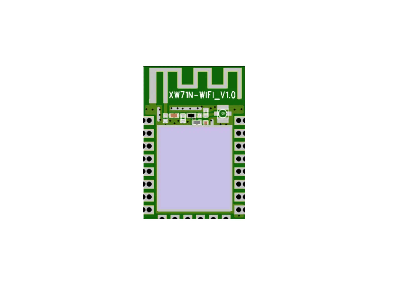
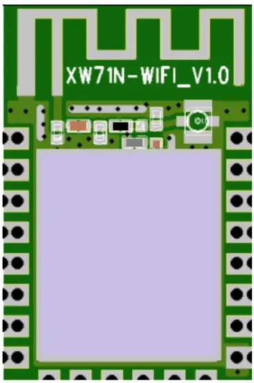
Product outline drawing
The physical size of the XW71N Wi-Fi module is 24mm*16mm*2.8mm, and the module has a built-in 2dBi PCB on-board antenna.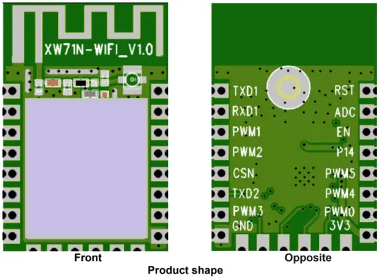
Product package dimension drawing
Package dimension
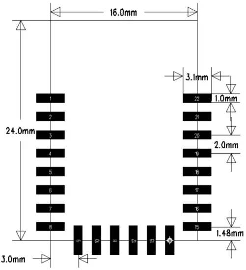
Module model | Long(mm) | Wide(mm) | High(mm) | PADsize(mm) | Pin spacing(mm) | thicknes s(mm) |
| XW71N-WIFI | 24 | 26 | 2.8±0.2 | 3.1X1.0 | 2.0 | 0.8 |
Pin definition
The XW71N-WIFI module connects a total of 22 interfaces, of which GPIO has 16.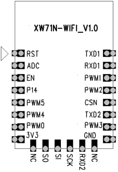
XW71N pin schematic
Table 2.3 Pin function definitions
| Number | Pin | Function description |
| 1 | RST | Reset pin (active low) |
| 2 | ADC3 | General IO, ADC3 |
| 3 | EN | General IO, Compatible with other module design docking |
| 4 | P14 | General IO, |
| 5 | PWM5 | General IO, PWM5 |
| 6 | PWM4 | General IO, PWM4 |
| 7 | PWM0 | General IO, PWM0 |
| 8 | 3V3 | Module total power input,Voltage2.8V~3.6V, Recommend3.3V 500mA |
| 9 | NC | – |
| 10 | OS | General IO, SPI Burn the mouth,not available |
| 11 | SI | General IO, SPI Burn the mouth,Not recommended |
| 12 | SCK | General IO, SPI Burn the mouth ,Not recommended |
| 13 | RXD2 | General IO, UART2_RXD(Used to print module internal information) |
| 14 | NC | – |
| 15 | GND | Module grounding pins |
| 16 | PWM3 | General IO, PWM3 |
| 17 | TXD2 | General IO, UART2_TXD(Used to print module internal information) |
| 18 | CSN | General IO, SPI Burn the mouth,Not recommended |
| 19 | PWM2 | General IO, PWM2 |
| 20 | PWM1 | General IO, PWM1 |
| 21 | RXD1 | General IO, UART1_RXD(Communicate with MCU) |
| 22 | TXD1 | General IO, UART1_TXD(Communicate with MCU) |
Hardware design
Minimal system
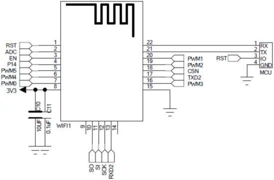
XW71N-WIFI module minimum system diagram
Explain:
- The module does not need additional components, only need to supply the module to work normally, the supply voltage is recommended 3.3V, the supply current is greater than 500mA;GPIOMaximum drive current is 8mA
- 1-pin RST, low active, there is a 10K pull-up resistor inside the module, which requires external MCU IO control
- The module’s UART1 is connected to the external MCU’s TXD, and the module’s TXD is connected to the RXD of the external MCU
- Module online upgrade, just connect the UART2 port, and then pull the RST down more than 15ms and then release it, or it can be reset by software
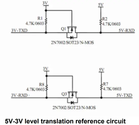
Serial 5V-3V level translation reference circuit
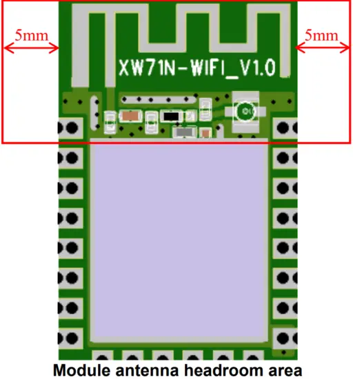
Antenna clearance area
XW71N needs to be soldered on the PCB board, in order to obtain the best RF performance, as shown in the following figure, the PCB on-board antenna below, there can be no copper, devices, traces, PCB design needs to be the corresponding area for headroom treatment.
RF parameter
RF Parameter table
| Parameter | MiX | Typical values | Max | Unit |
| Overall parameters | ||||
| Operating frequency | 2412 | 2472 | MHz | |
| Enter the impedance | 50 | Ω | ||
| Transmit power | ||||
| CH1 | CH7 | CH13 | ||
| Output power 802.11b@11Mbps) | 16 | 16 | 16 | dBm |
| Output power 802.11g@54Mbps) | 15 | 15 | 15 | dBm |
| Output power 802.11n@HT20,MCS7) | 14 | 14 | 14 | dBm |
| Receive sensitivity | ||||
| Sensitivity 802.11b@11Mbps,CCK) | -88 | -88 | -88 | dBm |
| Sensitivity | -74 | -74 | -74 | dBm |
| (802.11g@54Mbps,OFDM) | ||||
| Sensitivity 802.11n@HT20,MCS7) | -72 | -72 | -72 | dBm |
| Sensitivity(BLE 1M) | -93 | -93 | -93 | dBm |
Power consumption
The following power consumption data are measured data under 3.3V supply conditions
Power consumption meter
| Mode | Min | Type | Max | Unit |
| Transmit 802.11b, CCK 11Mbps, POUT=16dBm | 270 | mA | ||
| Transmit 802.11g, OFDM 54Mbps, POUT =15dBm | 260 | mA | ||
| Transmit 802.11n, MCS7, POUT =+14dBm | 253 | mA | ||
| Receive 802.11b,CCK,1Mbp | 73 | mA | ||
| Receive 802.11g,OFDM,54Mbp | 75 | mA | ||
| Receive 802.11n,HT20,MCS7 | 75 | mA |
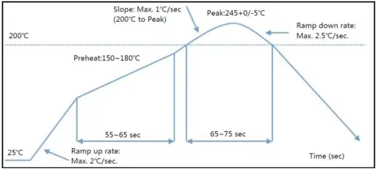
Furnace temperature curve
Maximum temperature:<250℃
Number of times the furnace is passed:≤2次
FCC Requirement
Any changes or modifications not expressly approved by the party responsible for compliance could void the user’s authority to operate the equipment.
This device complies with Part 15 of the FCC Rules. Operation is subject to the following two conditions:
(1) this device may not cause harmful interference, and
(2) this device must accept any interference received, including interference that may causeundesired operation.
Note: pursuant to Part 15 of the FCC Rules. These lim its are designed to provide reasonable protection against harm ful interference in a residential installation. This equipm ent generates, uses, and can radiate radio frequency energy, and if not installed and used in accordance with the instructions, m ay cause harm ful interference to radio com m unications. However, there is no guarantee that interference will not occur in a particular installation. If this equipm ent does cause harm ful interference to radio or television reception, which can be determ ined by turning the equipm ent off and on, the user is encouraged to try to correct the interference by one or m ore of the following m easures: Reorient or relocate the receiving antenna. Increase the separation between the equipm ent and receiver. Connect the equipm ent into an outlet on a circuit different from that to which the receiver is connected. Consult the dealer or an experienced radio/TV technician for help.
RF exposure considerations This modular complies with FCC RF radiation exposure limits set forth for an uncontrolled environment. This transmitter must not be co-located or operating in conjunction with any other antenna or transmitter.
RF Exposure – This device is only authorized for use in a mobile application. At least 20 cm of separation distance between the module and the user’s body must be maintained at all times.
A label must be affixed to the outside of final commercial product with the following statements: This device contains FCC ID: 2AW97-XW71N
Consistent with §2.909(a), the following text must be included within the user’s manual or operator instruction guide for the final commercial product
This modular complies with FCC RF radiation exposure limits set forth for an uncontrolled environment. This transmitter must not be co-located or operating in conjunction with any other antenna or transmitter.
This device is only authorized for use in a mobile application. At least 20 cm of separation distance between the module and the user’s body must be maintained at all times.
The final host / module combination may also need to be evaluated against the FCC Part 15B criteria for unintentional radiators in order to be properly authorized for operation as a Part 15 digital device. The FCC Part 15 Statement shall be included in the user manual of final commercial product if applicable.
CAUTION: Any changes or modifications not expressly approved could void the user’s authority to operate the equipment.


