Shenzhen Jixin Intelligence XR-22A Wi-Fi Module User Manual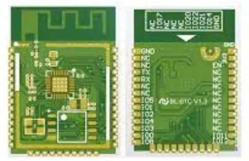
Product Overview
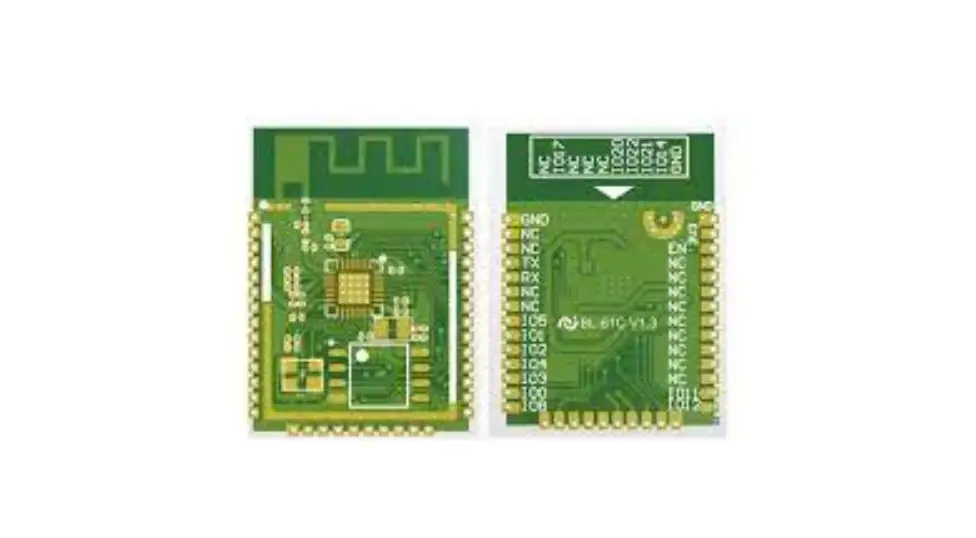
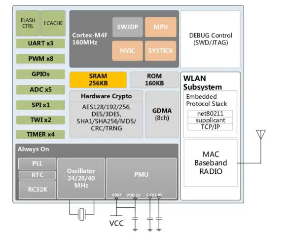
XR‐22A WiFi module was developed for a wide range of IoT applications, Its core processor XR808 integrates the ARM Cortex‐M4F 32‐bit microcontroller in a smaller package, supporting the master clock frequency up to 160MHz; Integrates high‐performance WLAN system with Wi‐Fi MAC/BB/RF/PA/LNA units; Integrates advanced power management units for ultra‐low power consumption with multiple sleep modes and fast wake‐up mechanisms; Integrates hardware encryption engine to supports AES/DES/3DES/SHA‐1/ MD5/ CRC/ SHA256/TRNG; Integrates large memory and rich peripherals. XR‐22A WiFi module supports standard IEEE802.11 b/g/n protocol, supports RTOS, with a complete
TCP/IP protocol stack, Users can use the module to add networking capabilities to existing devices, or can use it as a master design wireless network product, XR808 can be started directly from external flash memory, the on‐chip high‐speed buffer memory helps improve system performance and reduce RAM requirements.
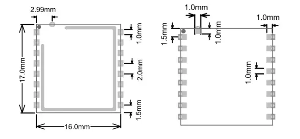
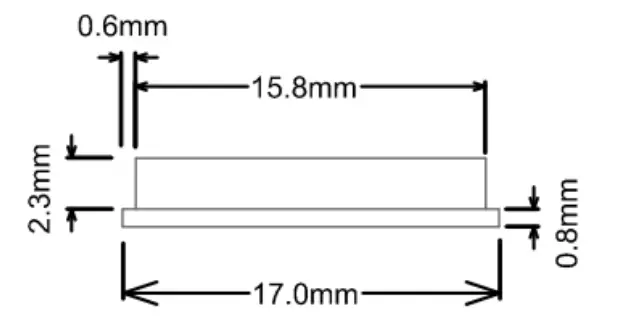
Appearance Dimensions
Features
- IEEE802.11b/g/n20,1×1SISO2.4GHz
- Built-in ARM Cortex-M4F 32bit MCU with main frequency from 32KHz to 160MHz,supportRTOS
- Built-in256KBSRAMand160KBROM
- SupportexternalFlashandeXecuteInPlace(XIP)
- 8shareduniversalDMAchannels
- Built-in6ways12bitSARtypeA/Dconverter
- Built-inWi-FiMAC/BB/RF/PA/LNA
- SupportWEP,WPA/WPA2,WPS2.0
- SupportUART/GPIO/ADC/PWM/I2C/SPIinterface
- UseSMD-17assemblemodel
- Supportmultiplesleepmodesandcurrentaslowas4uAindeep sleepmode
SupportAES/DES/3DES/SHA/MD5/CRCencryptionengine - SupportSTA/AP/STA+APoperationmodes
- SupportSmartConfig/AirKiss(WeChat)
- SupportLocalfirmwareupgradeusingUARTandremoteupgrad (FOTA)
- HasuniversalandfriendlyATcommandset
- Supportsecondarydevelopment,supportWindows,Linux developmentenvironment
Key parameter
Table1.1Descriptionofthemainparameters
| Module model | XR-22A |
| Mounting | SMD17 |
| Size(mm) | 17*16*3(±0.2)mm |
| Cert. | FCC、CE、IC、REACH、RoHS |
| SPI Flash | 32Mbit(default) |
| Interface | UART/GPIO/ADC/PWM/ I2C /SPI |
| Number of GPIO | 13 |
| UART baud | 9600/19200/38400/115200/921600 bps |
| Freq. | 2412 ~2462MHz |
| Antenna | FPC |
| Tx Power | 802.11b: 17±2 dBm (@11Mbps) 802.11g: 15±2 dBm (@54Mbps) 802.11n: 14±2 dBm (@HT20, MCS7) |
| Rx Sensitivity | CCK, 1 Mbps : -96dBm CCK, 11 Mbps: -91dBm 6 Mbps (1/2 BPSK): -92dBm |
| 54 Mbps (3/4 64-QAM): -75dBm HT20, MCS7 (65 Mbps, 72.2 Mbps): -73dBm | |
| Power dissipation (Typical) | RX Active(MCU active, DC-DC mode):31mA TX Active(MCU active, DC-DC mode): 164mA@11n MCS7 14dBm 192mA@11b CCK 19dBm Standby: ~26.5uA Hibernation: ~4uA Shutdown: ~0.5uA |
| Security | WEP/WPA-PSK/WPA2-PSK/WPS2.0 |
| Power Supply | DC 2.7V ~ 5.5V,Imax >300mA |
| Temperature | -40 ℃ ~ +85 ℃ |
| Storage Condition | -55 ℃ ~ 150℃ ,< 90%RH |
Pin definition
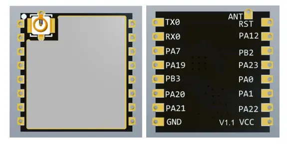
XR-22Amodule has 17pins,features are shownin Figure 2.1 and Table2.2
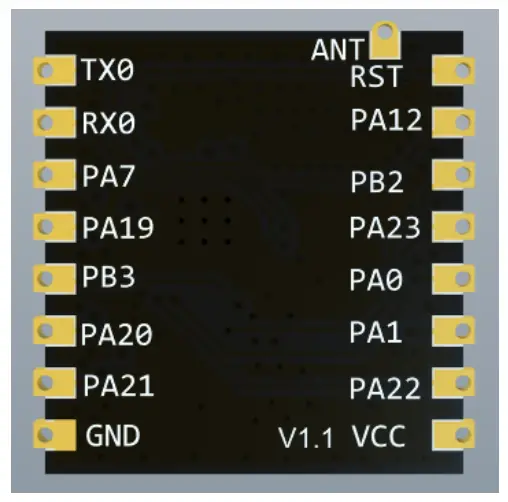
Table2.2Pindescription
| Number | Name | Function description |
| 1 | RST | Reset |
| 2 | PA12 | ADC_CH2;PWM4/ECT4;IR_TX;EINTA12 |
| 3 | PB2 | SWD_TMS;JTAG_TD0;PWM6/ECT6;EINTB2;download mode: pull-down,work mode: do not handle or pull-up |
| 4 | PA23 | EXT_DCDC_PUP ; WUPIO9(wake up IO) ; EINTA23 ;default cannot be high |
| 5 | PA0 | TWI1_SCL;EINTA0 |
| 6 | PA1 | TWI1_SDA;EINTA1 PA18;TWI0_SDA;IR_TX;IR_RX;EINTA18 |
| 7 | PA22 | UART2_TX;PWM3/ECT3;SPI1_CS0;WUPIO8;EINTA22 |
| 8 | VCC | power supply, 2.7~5.5V; |
| 9 | GND | ground |
| 10 | PA21 | UART2_RX; PWM2/ECT2;SPI1_CLK;WUPIO7;EINTA21 |
| 11 | PA20 | UART2_CTS;TWI0_SDA;PWM1/ECT1;SPI1_MISO; WUPIO6; EINTA20 |
| 12 | PB3 | SWD_TCK;JTAG_TDI;PWM7/ECT7;EINTB3; download mode :pull-down, Run mode :do not handle or pull-up |
| 13 | PA19 | UART2_RTS;TWI0_SCL;PWM0/ECT0;SPI1_MOSI; WUPIO5; EINTA19 |
| 14 | PA7 | UART1_TX;TWI0_SDA;EINTA7; PA17;WUPIO4;TWI0_SCL;IR_RX;32KOSCO;EINTA17 |
| 15 | RX0 | UART0_RX;JTAG_TCK;PWM5/ECT5;SWD_TCK;EINTB1 |
| 16 | TX0 | UART0_TX; JTAG_TMS;PWM4/ECT4;SWD_TMS;EINTB0 |
| 17 | ANT | Reserved antenna pin |
Table2.3 Startmode
| mode | RST | PB2 | PB3 |
| Download | rising edge | low | low |
| Run | rising edge | low | high |
| high | low | ||
| high | high |
Notice: PB2andPB3hadbeen pulledupinmodule,modulehasself-resetfunction
Electrical parameters
Electrical characteristics
| parameter | test condition | min | typ | max | unit | |
| Storage Temp. | – | -55 | normal | 150 | ℃ | |
| Work temp. | – | -40 | 20 | 85 | ℃ | |
| Max welding temp. | IPC/JEDEC J-STD-020 | – | – | 260 | ℃ | |
| Supply volt. | VCC | 2.7 | 3.3/5 | 5.5 | V | |
| I/O | VIL | VCC_IO=3.3V | -0.3 | – | 1.32 | V |
| VIH | VCC_IO=3.3V | 2.06 | – | 3.6 | V | |
| VOL | VCC_IO=3.3V, |IOL|=7.5~50 mA | -0.3 | – | 0.4 | V | |
| VOH | VCC_IO=3.3V, |IOL|=7.5~50 mA | 2.9 | – | 3.4 | V | |
| IMAX | – | – | – | 12 | mA |
Wi-Fi RF characteristic
| Description | Min | Typ. | Max | Unit |
| Central Freq. | 2412 | – | 2462 | MHz |
| Enter reflection value | – | – | -10 | dB |
| Transmit Power | ||||
| CCK, 1 Mbps | 17.22 | 17.64 | – | dBm |
| CCK, 11Mbps | 16.83 | 17.20 | – | dBm |
| 6 Mbps OFDM | 16.92 | 18.17 | – | dBm |
| 54Mbps OFDM | 15.02 | 15.13 | – | dBm |
| HT20, MCS0 | 16.68 | 18.05 | – | dBm |
| HT20, MCS7 | 14.71 | 15.19 | – | dBm |
| EVM | ||||
| CCK, 1 Mbps | -20.36 | -20.75 | – | dB |
| CCK, 11Mbps | -21.66 | -21.78 | – | dB |
| 6 Mbps OFDM | -21.63 | -24.35 | – | dB |
| 54Mbps OFDM | -33.86 | -34.17 | – | dB |
| HT20, MCS0 | -25.43 | -28.72 | – | dB |
| HT20, MCS7 | -34.49 | -34.58 | – | dB |
| Receiver Sensitivity | ||||
| CCK, 1 Mbps | – | -96 | – | dBm |
| CCK, 11 Mbps | – | -91 | – | dBm |
| 6 Mbps OFDM | – | -92 | – | dBm |
| 54 Mbps OFDM | – | -75 | – | dBm |
| HT20, MCS0 | – | -91 | – | dBm |
| HT20, MCS7 | – | -73 | – | dBm |
Power dissipation
XR808,25℃,VCC=3.3V,VDD-ANA=1.8V,MCU160MHz
| Work mode | MCU state | WLAN state | TX/RX | Test condition | Min. | Typ. | Max. | unit | |
| ACTIVE | Active | Active | TX | 1M DSSS | 17dBm | ‐ | 217.0 | ‐ | mA |
| 11M CCK | 17dBm | ‐ | 224.0 | ‐ | mA | ||||
| 6M OFDM | 16dBm | ‐ | 200.0 | ‐ | mA | ||||
| 54M OFDM | 16dBm | ‐ | 212.0 | ‐ | mA | ||||
| HT20,M CS0 | 16dBm | ‐ | 209.0 | ‐ | mA | ||||
| HT20,M CS7 | 15dBm | ‐ | 204.0 | ‐ | mA | ||||
| RX | 1M DSSS | ‐ | 39.0 | ‐ | mA | ||||
| 11M CCK | ‐ | 40.0 | ‐ | mA | |||||
| 54M OFDM | ‐ | 46.0 | ‐ | mA | |||||
| HT20,MCS0 | ‐ | 42.0 | ‐ | mA | |||||
| HT20,MCS7 | ‐ | 49.0 | ‐ | mA | |||||
| STANDBY | Sleep | Active | TX | 1M DSSS,nu ll frame | 17dBm | ‐ | 217.0 | ‐ | mA |
| RX | RX listen | ‐ | 40.5 | ‐ | mA | ||||
| 1M DSSS | ‐ | 33.3 | ‐ | mA | |||||
| PS Mode | RX | DTIM1 | ‐ | 1074. 0 | ‐ | uA | |||
| DTIM3 | ‐ | 435.0 | ‐ | uA | |||||
| DTIM8 | ‐ | 200.0 | ‐ | uA | |||||
| DTIM10 | ‐ | 167.0 | ‐ | uA | |||||
| OFF | ‐ | ‐ | ‐ | 47.0 | ‐ | uA | |||
| HIBERNATION | OFF | OFF | ‐ | ‐ | ‐ | 3.5 | ‐ | uA | |
| SHUTDOWN | OFF | OFF | ‐ | ‐ | ‐ | 0.5 | ‐ | uA | |
Notice:
- ACTIVE mode,the power dissipation value is tested in MCU and WLAN activating.
- STANDBY mode ,MCU is in sleep,can be awakened by peripherals
For example:When the system has no task for a long time and needs to be connected to the network, close most peripherals, retain the network communication capacity, and wake up the system for processing as soon as possible when the data is received. - HIBERNATION mode retains only RTC, waiting for Timer or wake up IO interrupt
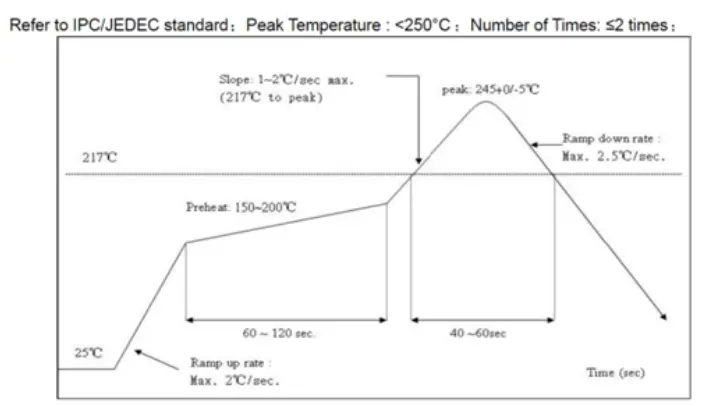
Reflow welding temperature curve
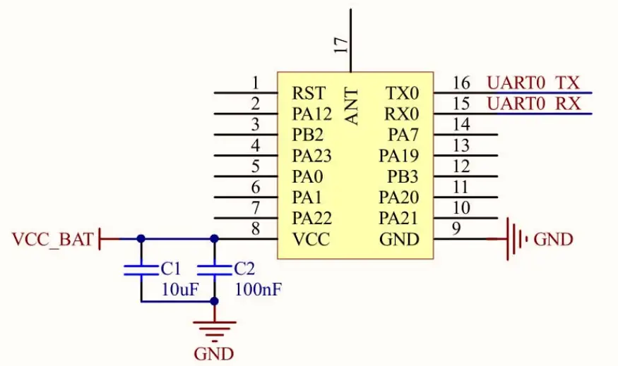
Application circuit
Federal Communication Commission Statement (FCC, U.S.)
This equipment has been tested and found to comply with the limits for a Class B digital device, pursuant to Part 15 of the FCC Rules. These limits are designed to provide reasonable protection against harmful interference in a residential installation. This equipment generates, uses and can radiate radio frequency energy and, if not installed and used in accordance with the instructions, may cause harmful interference to radio communications. However, there is no guarantee that interference will not occur in a particular installation. If this equipment does cause harmful interference to radio or television reception, which can be determined by turning the equipment off and on, the user is encouraged to try to correct the interference by one of the following measures:
- Reorient or relocate the receiving antenna.
- Increase the separation between the equipment and receiver.
- Connect the equipment into an outlet on a circuit different from that to which the receiver is connected.
- Consult the dealer or an experienced radio/TV technician for help
This device complies with Part 15 of the FCC Rules. Operation is subject to the following two conditions: (1) This device may not cause harmful interference, and (2) this device must accept any interference received, including interference that may cause undesired operation.
FCC Caution:
Any changes or modifications not expressly approved by the party responsible for compliance could void the user’s authority to operate this equipment.
IMPORTANT NOTES
Co-location warning:
This transmitter must not be co-located or operating in conjunction with any other antenna or transmitter.
OEM integration instructions:
This device is intended only for OEM integrator under the following conditions:
The transmitter module may not be co-located with any other transmitter or antenna. The module shall be only used with the external antenna(s) that has been originally tested and certified with this module.
As long as the conditions above are met, further transmitter test will not be required. However, the OEM integrator is still responsible for testing their end-product for any additional compliance requirements required with this module installed (for example, digital device emissions, PC peripheral requirements, etc.).
- The antenna must be installed such that 20 cm is maintained between the antenna and users, and
- This device and its antenna(s) must not be co‐located with any other transmitters except in accordance with FCC multi‐transmitter product procedures. Referring to the multi‐transmitter policy, multiple‐transmitter(s) and module(s) can be operated simultaneously without C2P.
- For all products market in US, OEM has to limit the operation channels in CH1 to CH11 for 2.4G band by supplied firmware programming tool. OEM shall not supply any tool or info to the end‐user regarding to Regulatory Domain change.
Validity of using the module certification:
In the event that these conditions cannot be met (for example certain laptop configurations or co-location with another transmitter), then the FCC authorization for this module in combination with the host equipment is no longer considered valid and the FCC ID of the module cannot be used on the final product. In these circumstances, the OEM integrator will be responsible for re-evaluating the end product (including the transmitter) and obtaining a separate FCC authorization.
End product labeling:
The final end product must be labeled in a visible area with the following: “Contains Transmitter Module FCC ID: 2AVTT-XR22A”.
Information that must be placed in the end user manual:
The OEM integrator has to be aware not to provide information to the end user regarding how to install or remove this RF module in the user’s manual of the end product which integrates this module. The end user manual shall include all required regulatory information/warning as show in this manual.
Integration instructions for host product manufacturers according to KDB 996369 D03 OEM Manual v01
List of applicable FCC rules
FCC Part 15 Subpart C 15.247 & 15.207 & 15.209
Specific operational use conditions
The module is a WIFI module with WIFI 2.4G function.
Operation Frequency: 2412~2462MHz
Number of Channel: 11
Modulation: 802.11b CCK; 802.11g/n OFDM
Type: FPC Antenna
Gain: 2 dBi Max.
The module can be used for mobile or applications with a maximum 2dBi antenna. The host manufacturer installing this module into their product must ensure that the final composit product complies with the FCC requirements by a technical assessment or evaluation to the FCC rules, including the transmitter operation. The host manufacturer has to be aware not to provide information to the end user regarding how to install or remove this RF module in the user’s manual of the end product which integrates this module. The end user manual shall include all required regulatory information/warning as show in this manual.
Limited module procedures
Not applicable. The module is a Single module and complies with the requirement of FCC Part 15.212.
Trace antenna designs
Not applicable. The module has its own antenna, and doesn’t need a host’s printed board microstrip trace antenna etc.
RF exposure considerations
The module must be installed in the host equipment such that at least 20cm is maintained between the antenna and users’ body; and if RF exposure statement or module layout is changed, then the host product manufacturer required to take responsibility of the module through a change in FCC ID or new application. The FCC ID of the module cannot be used on the final product. In these circumstances, the host manufacturer will be responsible for re-evaluating the end product (including the transmitter) and obtaining a separate FCC authorization.
Antennas
Antenna Specification are as follows:
Type: FPC Antenna
Gain: 2 dBi
This device is intended only for host manufacturers under the following conditions: The transmitter module may not be co-located with any other transmitter or antenna; The module shall be only used with the internal antenna(s) that has been originally tested and certified with this module. The antenna must be either permanently attached or employ a ‘unique’ antenna coupler.
As long as the conditions above are met, further transmitter test will not be required. However, the host manufacturer is still responsible for testing their end-product for any additional compliance requirements required with this module installed (for example, digital device emissions, PC peripheral requirements, etc.).
Label and compliance information
Host product manufacturers need to provide a physical or e-label stating “Contains FCC ID: 2AVTTXR22A”with their finished product.
Information on test modes and additional testing requirements
Operation Frequency: 2412~2462MHz
Number of Channel: 11
Modulation: 802.11b CCK; 802.11g/n OFDM
Host manufacturer must perfom test of radiated & conducted emission and spurious emission, etc according to the actual test modes for a stand-alone modular transmitter in a host, as well as for multiple simultaneously transmitting modules or other transmitters in a host product. Only when all the test results of test modes comply with FCC requirements, then the end product can be sold legally.
Additional testing, Part 15 Subpart B disclaimer
The modular transmitter is only FCC authorized for FCC Part 15 Subpart C 15.247 & 15.207 & 15.209 and that the host product manufacturer is responsible for compliance to any other FCC rules that apply to the host not covered by the modular transmitter grant of certification. If the grantee markets their product as being Part 15 Subpart B compliant (when it also contains unintentional-radiator digital circuity), then the grantee shall provide a notice stating that the final host product still requires Part 15 Subpart B compliance testing with the modular transmitter installed.
FCC STATEMENT
This device complies with Part 15 of the FCC Rules. Operation is subject to the following two conditions
- This device may not cause harmful interference, and
- This device must accept any interference received, including interference that may cause undesired operation.
Warning: Changes or modifications not expressly approved by the party responsible for compliance could void the user’s authority to operate the equipment.
NOTE: This equipment has been tested and found to comply with the limits for a Class B digital device, pursuant to Part 15 of the FCC Rules. These limits are designed to provide reasonable protection against harmful interference in a residential installation. This equipment generates uses and can radiate radio frequency energy and, if not installed and used in accordance with the instructions, may cause harmful interference to radio communications. However, there is no guarantee that interference will not occur in a particular installation. If this equipment does cause harmful interference to radio or television reception, which can be determined by turning the equipment off and on, the user is encouraged to try to correct the interference by one or more of the following measures:
- Reorient or relocate the receiving antenna.
- Increase the separation between the equipment and receiver.
- Connect the equipment into an outlet on a circuit different from that to which the receiver is connected.
- Consult the dealer or an experienced radio/TV technician for help.
FCC Radiation Exposure Statement:
This equipment complies with FCC radiation exposure limits set forth for an uncontrolled environment. This equipment should be installed and operated with minimum distance 20cm between the radiator & your body.
Contact Us
Address: A505Room, BusinessBuilding, SuojiaSciencePark , Xixiang, BaoanDistrict, Shenzhen
Telephone :0755-23220940
Website :www.aimachip.com


