WM-8710BNSIP WIFI Module Manual
General Information
| category | WIFI Module |
| Drawing Number | MW-8710BNSIP |
| Model | MW-8710BNSIP |
| Environmental requirements | RoHS, REACH |
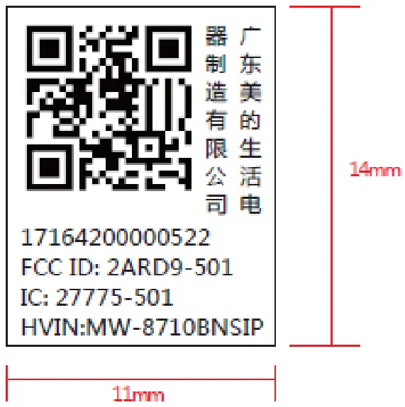
| Number | 17164200000522 |
| Electrostatic level | Contact discharge+/-4KV,Air discharge +/-8KV |
| Certification number | FCC ID:2ARD9-501 IC :27775-501 |
Technical information
The scheme is based on RTL8710BN(W302)and uses a few peripheral components to realize the conversion from UART to WiFi signal。
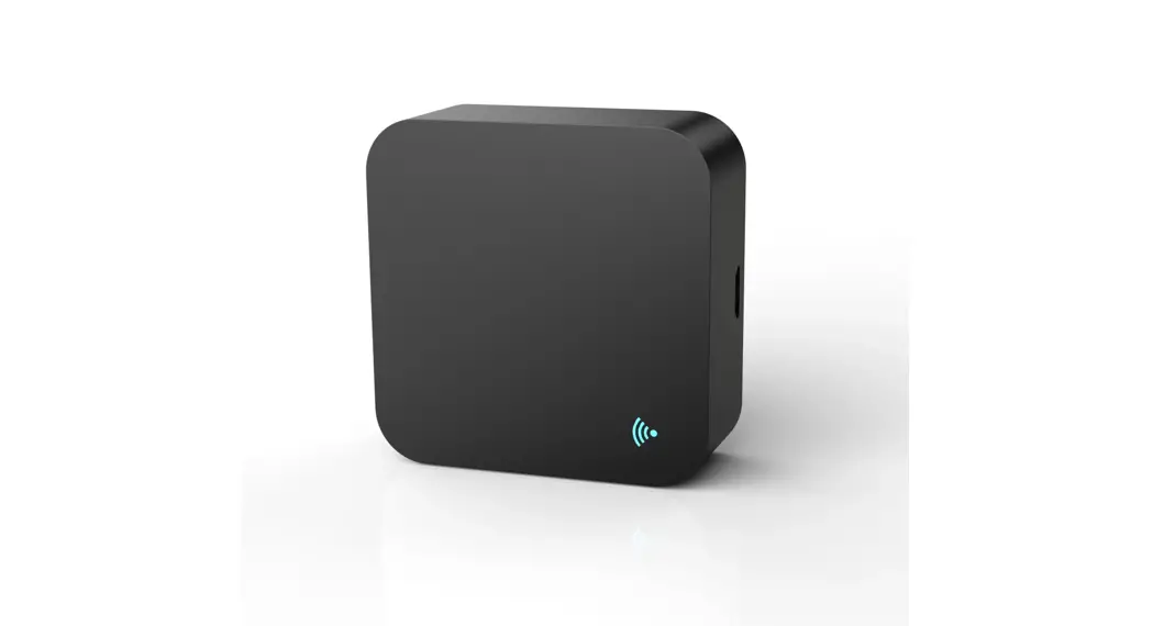
2. 1 Appearance
Front view of the module
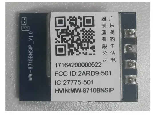
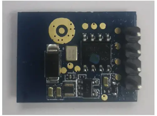
Product back view
2. 2 Dimension
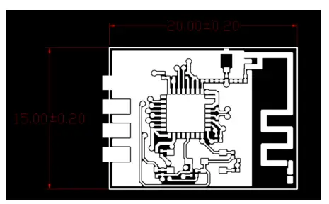
| definition | Length | Width | Thickness |
| dimension(mm) | 20 | 15 | 1 |
| error(mm) | ±0.2 | ±0.2 | ±0.2 |
| PIN length | 3.6mm±0.2mm | ||
2. 3 PIN name
| Pin No. | WiFi module pin description |
| 1 | VCC: Power supply pin |
| 2 | RDX: Signal receiving pin |
| 3 | TXD: Signal transmitting pin |
| 4 | GND: System ground PIN |
2. 4 Marking 13mm*11mm
2. 5 Parameters
No. | performance parameter | technical requirement | Note |
1 | MCU | RTL8710BN (W302) | |
2 | Operating frequency | 2412 – 2462 MHz | |
3 | Supported WiFi standards | 802. 11b/g/n (1T1R) | |
1 | modulation mode | 802.11b: DSSS (CCK, DBPSK, DBPSK) 802.11g: OFDM (64QAM, 16QAM, QPSK,BPSK) 802.11n HT20: OFDM (64QAM, 16QAM, QPSK,BPSK) 802.11n HT40: OFDM (64QAM, 16QAM, QPSK,BPSK) | |
5 | Supported rate | llb: 1, 2, 5.5 full 11Mbps 11g: 6,9,12,18,24,36,48,54Mbps ln: MCSO–7, up to 150Mbps | |
6 | Communication mode | CART | |
7 | Number of PCB layers | 4-Layers Design | |
8 | PCB size | 20ram(L)z15mm(Ez1.0mm(H) | |
9 | Crystal oscillator voltage input range | 0. 1Vpp to 1. 5Vpp | |
10 | Operating ambient temperature (TA) | -20t–85″C | |
11 | Antenna type | PCB | |
12 | Operating temperature | -20’C—+85t | |
13 | Storage temperature | -40C^-+85C | |
14 | working voltage | 5. 0V+/-5% |
Description of key parameters
The key parameter of the module is the RF characteristic parameter of the module (the corresponding modulation characteristics of the module under different modulation modes), which represents the communication quality of the module in actual work.
Test method: Measure according to IEEE802.11b/g/n standard。
Electrical specifications
802.11b Mode
Parameters | Specifications | ||||
| Specification | IEEE802.11b | ||||
| Mode | DSSS / CCK | ||||
| Channel | CH1 to CH13 | ||||
| Data rate | 1, 2, 5.5, 11Mbps | ||||
| DC Characteristics | Min. | Typ. | Max. | ||
| 1. DC current (Average) @5.0V input | |||||
| 1) TX only @17dBm | 229 | mA | |||
| 2) TX throughput mode | 120 | mA | |||
| 3) RX throughput mode | 100 | mA | |||
| TX Characteristics | Min. | Typ. | Max. | Unit | |
| 2. Power Levels(Calibrated) | |||||
| 1) 17dBm Target | 15 | 17 | 18 | dBm | |
| 3. Spectrum Mask @ target power | |||||
| 1) fc +/-11MHz to +/-22MHz | – | – | -30 | dBr | |
| 2) fc > +/-22MHz | – | – | -50 | Br | |
| 4. Frequency Error | -25 | 0 | +25 | pm | |
RX Characteristics | Min. | Typ. | Max. | Unit | |
| 5 Minimum Input Level Sensitivity | |||||
| 1) 1Mbps (FER ≦8%) | – | – | -83 | dBm | |
| 2) 2Mbps (FER ≦8%) | – | – | -80 | dBm | |
| 3) 5.5Mbps (FER ≦8%) | – | – | -79 | dBm | |
| 4) 11Mbps (FER ≦8%) | – | -90 | -76 | dBm | |
| 6 Maximum Input Level (FER ≦8%) | -20 | -10 | 1 | dBm | |
802.11g
Parameters | Specifications | ||||
| Specification | IEEE802.11g | ||||
| Mode | OFDM | ||||
| Channel | CH1 to CH13 | ||||
| Data rate | 6, 9, 12, 18, 24, 36, 48, 54Mbps | ||||
DC Characteristics | Min. | Typ. | Max. | Unit | Remark |
| 1. DC current (Average) @5.0V input | |||||
| 1) TX only @17dBm | – | 270 | mA | ||
| 2) TX throughput mode | – | 120 | mA | ||
| 3) RX throughput mode | – | 100 | mA | ||
TX Characteristics | Min. | Typ. | Max. | Unit | |
| 2. Power Levels | |||||
| 1) 16dBm Target @6Mbps | 14 | 16 | 18 | dBm | |
| 2) 14dBm Target @54Mbps | 12 | 14 | 16 | dBm | |
| 3. Spectrum Mask @ target power | |||||
| 1) at fc +/- 11MHz | – | – | -20 | Br | |
| 2) at fc +/- 20MHz | – | – | -28 | dBr | |
| 3) at fc > +/-30MHz | – | – | -40 | Br | |
| 4 Constellation Error(EVM)@ target power | |||||
| 1) 6Mbps | – | – | -5 | dB | |
| 2) 9Mbps | – | – | -8 | dB | |
| 3) 12Mbps | – | – | -10 | dB | |
| 4) 18Mbps | – | – | -13 | dB | |
| 5) 24Mbps | – | – | -16 | dB | |
| 6) 36Mbps | – | – | -19 | dB | |
| 7) 48Mbps | – | – | -22 | dB | |
| 8) 54Mbps | – | -30 | -25 | dB | |
| 5 Frequency Error | -25 | 0 | +25 | ppm | |
| RX Characteristics | Min. | Typ. | Max. | Unit | |
| 6 Minimum Input Level Sensitivity | |||||
| 1) 6Mbps (PER -= 10%) | – | – | -85 | dBm | |
| 2) 9Mbps (PER –.- 10%) | – | – | -84 | dBm | |
| 3) 12Mbps (PER =_– 10%) | – | – | -82 | dBm | |
| 4) 18Mbps (PER === 10%) | – | – | -80 | dBm | |
| 5) 24Mbps (PER =_– 10%) | – | – | -77 | dBm | |
| 6) 36Mbps (PER =_– 10%) | – | – | -73 | dBm | |
| 7) 48Mbps (PER …== 10%) | – | – | -69 | dBm | |
| 8) 54Mbps (PER= 10%) | – | -76 | -68 | dBm | |
| 7 Maximum Input Level (PER ––––-z 10%) | -20 | -10 | 1 | dBm |
802.11n HT20
| Specification | IEEE802.11n HT20 @ 2.4GHz | ||||
| Mode | OFDM | ||||
| Channel | CH1 to CH13 | ||||
| Data rate (MCS index) | MCS0/1/2/3/4/5/6// | ||||
| DC Characteristics | Min. | Typ. | Max. | Unit | Remark |
| 1. DC current (Average) @5.0V input | |||||
| 1) TX only @ 17(iii Target(each port), (continue Tx MIMO MCS7) | 229 | mA | |||
| 2) TX throughput mode | 120 | mA | |||
| 3) RX throughput mode | 100 | mA | |||
| TX Characteristics | Min. | Typ. | Max. | Unit | |
| 2. Power Levels | |||||
| 1) 16dBm Target@MCSO | 14 | 16 | 18 | dBm | |
| 2) 13dBm Target@MCS7 | 11 | 13 | 15 | dBm | |
| 3. Spectrum Mask @target power | |||||
| 1) at fc +/- 11MHz | -20 | Br | |||
| 2) at fc +/- 20MHz | -28 | Br | |||
| 3) at fc > +/-30MHz | -45 | Br | |||
| 4. Constellation Error(EVM)@ target power | |||||
| 1) MCSO | dB | ||||
| 2) MCS1 | -10 | dB | |||
| 3) MCS2 | -13 | dB | |||
| 4) MCS3 | -16 | dB | |||
| 5) MCS4 | -19 | dB | |||
| 6) MCS5 | -22 | dB | |||
| 7) MCS6 | -25 | dB | |||
| 8) MCS7 | – | -30 | -28 | dB | |
| 5. Frequency Error | -25 | 0 | +25 | ppm | |
| RX Characteristics | Min. | Typ. | Max. | Unit | |
| 6. Minimum Input Level Sensitivity | |||||
| 1) MCSO (PER -_-=: 10%) | -85 | dBm | |||
| 2) MCS1 (PER Lfis 10%) | -82 | dBm | |||
| 3) MCS2 (PER _=-: 10%) | -80 | dBm | |||
| 4) MCS3 (PER -=_= 10%) | -77 | dBm | |||
| 5) MCS4 (PER Ls: 10%) | -73 | dBm | |||
| 6) MCS5 (PER -=_= 10%) | -69 | dBm | |||
| 7) MCS6 (PER Ls-: 10%) | -68 | dBm | |||
| 8) MCS7 (PER _=-: 10%) | – | -73 | -67 | dBm | |
| 7. Maximum Input Level (PER – 10%) | -20 | -10 | 1 | dBm |
802.11n HT40
| Parameters | Specifications | ||||
| Specification | IEEE802.11n HT40 @ 2.4GHz | ||||
| Mode | OFDM | ||||
| Channel | CH3 to CH11 | ||||
| Data rate (MCS index) | MCSO/1/2/3/4/5/6/7 | ||||
| DC Characteristics | Min. | Typ. | Max. | Unit | Remark |
| 1. DC current (Average) @5.0V input | |||||
| 1) TX only (a, I 4dBm Target | 220 | mA | |||
| 2) TX throughput mode | 120 | mA | |||
| 3) RX throughput mode | 100 | mA | |||
| TX Characteristics | Min. | Typ. | Max. | Unit | |
| 2. Power Levels | |||||
| 1) 14dBm Target@MCSO | 12 | 14 | 16 | dBm | |
| 2) 12dBm Target@MCS7 | 10 | 12 | 14 | dBm | |
| 3. Spectrum Mask @target power | |||||
| 1) at fc +/- 11MHz | – | -20 | · Br | ||
| 2) at fc +/- 20MHz | – | -28 | dBr | ||
| 3) at fc > +/-30MHz | – | -45 | · Br | ||
| 4. Constellation Error(EVM)@ target power | |||||
| 1) MCSO | – | -5 | dB | ||
| 2) MCS1 | – | -10 | dB | ||
| 3) MCS2 | – | -13 | dB | ||
| 4) MCS3 | – | -16 | dB | ||
| 5) MCS4 | -19 | dB | |||
| 6) MCSS | -22 | dB | |||
| 7) MCS6 | -25 | dB | |||
| 8) MCS7 | -30 | -28 | dB | ||
| 5. Frequency Error | -25 | 0 | +25 | ppm | |
| RX Characteristics | Min. | Typ. | Max. | Unit | |
| 6. Minimum Input Level Sensitivity | |||||
| 1) MCSO (PER = 10%) | -85 | dBm | |||
| 2) MCS1 (PER L=- 10%) | -82 | dBm | |||
| 3) MCS2 (PER =.-= 10%) | -80 | dBm | |||
| 4) MCS3 (PER .a.-= 10%) | -77 | dBm | |||
| 5) MCS4 (PER =.-= 10%) | -73 | dBm | |||
| 6) MCSS (PER .a.-= 10%) | -69 | dBm | |||
| 7) MCS6 (PER .a.-= 10%) | -68 | dBm | |||
| 8) MCS7 (PER =.-= 10%) | -70 | -62 | dBm | ||
| 7. Maximum Input Level (PER = 10%) | -20 | -10 | 1 | dBm |
FCC Statement
This equipment has been tested and found to comply with the limits for a Class B digital device, pursuant to part 15 of the FCC rules. These limits are designed to provide reasonable protection against harmful interference in a residential installation. This equipment generates, uses, and can radiate radio frequency energy and, if not installed and used in accordance with the instructions, may cause harmful interference to radio communications. However, there is no guarantee that interference will not occur in a particular installation. If this equipment does cause harmful interference to radio or television reception, which can be determined by turning the equipment off and on, the user is encouraged to try to correct the interference by one or more of the following measures:
-Reorient or relocate the receiving antenna.
-Increase the separation between the equipment and receiver.
-Connect the equipment into an outlet on a circuit different from that to which the receiver is connected.
-Consult the dealer or an experienced radio/TV technician for help.
This equipment complies with Part 15 of the FCC Rules. Operation is subject to the following two conditions:
(1) This device may not cause harmful interference, and
(2) This device must accept any interference received, including interference that may cause undesired operation.
Any changes or modifications not expressly approved by the party responsible for compliance could void the user’s authority to operate the equipment.
Please notice that if the FCC identification number is not visible when the module is installed inside another device, then the outside of the device into which the module is installed must also display a label referring to the enclosed module. This exterior label can use wording such as the following:
“Contains FCC ID: 2ARD9-501” any similar wording that expresses the same meaning may be used.
This equipment complies with FCC radiation exposure limits set forth for an uncontrolled environment. This equipment should be installed and operated with a minimum distance of 20cm between the radiator & your body. This transmitter must not be co-located or operating in conjunction with any other antenna or transmitter.
The device must be professionally installed
The intended use is generally not for the general public. It is generally for industry/commercial use.
The connector is within the transmitter enclosure and can only be accessed by disassembly of the transmitter that is not normally required. the user has no access to the connector.
Installation must be controlled. Installation requires special training
The module is limited to OEM installation ONLY.
The OEM integrator is responsible for ensuring that the end-user has no manual instruction to remove or install-module.
The module is limited to installation in mobile applications.
Separate approval is required for all other operating configurations, including portable configurations with respect to Part 2.1093 and difference antenna configurations.
There is a requirement that the grantee provides guidance to the host manufacturer for compliance with Part 15B requirements.
The module complies with FCC Part 15.247 and applies for Single module approval.
Antenna type: PCB antenna
Antenna Gain: 2dBi
Canada Statement
This device complies with Industry Canada’s license-exempt RSS. Operation is subject to the following two conditions:
(1) This device may not cause interference; and
(2) This device must accept any interference, including interference that may cause undesired operation of the device.
Please notice that if the ISED certification number is not visible when the module is installed inside another device, then the outside of the device into which the module is installed must also display a label referring to the enclosed module. This exterior label can use wording such as the following: “Contains IC: 27775-501” any similar wording that expresses the same meaning may be used.
The device meets the exemption from the routine evaluation limits in section 2.5 of RSS 102 and compliance with RSS-102 RF exposure, users can obtain Canadian information on RF exposure and compliance.
This transmitter must not be co-located or operating in conjunction with any other antenna transmitter. This equipment should be installed and operated with a minimum distance of 20 centimeters between the radiator and your body.
Notice to OEM integrator
Must use the device only in host devices that meet the FCC/ISED RF exposure category of mobile, which means the device is installed and used at distances of at least 20cm from persons. This transmitter must not be co-located or operating in conjunction with any other antenna or transmitter. The end-user manual shall include FCC Part 15 /ISED RSS GEN compliance statements related to the transmitter as shown in this manual(FCC/Canada statement). The host manufacturer is responsible for compliance of the host system with the module installed with all other applicable requirements for the system such as Part 15 B, ICES 003. The host manufacturer is strongly recommended to confirm compliance with FCC/ISED requirements for the transmitter when the module is installed in the host. The use condition limitations extend to professional users, then instructions must state that this information also extends to the host manufacturer’s instruction manual. This module is a stand-alone modular. If the end product will involve Multiple simultaneously transmitting conditions or different operational conditions for a stand-alone modular transmitter in a host, the host manufacturer has to consult with the module manufacturer for the installation method in the end system. Any company of the host device which install this modular should perform the test of radiated & conducted emission and spurious emission etc. according to FCC Part 15C: 15.247 and 15.209 & 15.207, 15B class B requirement, only if the test result complies with FCC part 15C: 15.247 and 15.209 & 15.207, 15B class B requirement. Then the host can be sold legally. This modular transmitter is only FCC authorized for the specific rule parts ( 47CFR Part 15.247) listed on the grant, and that the host product manufacturer is responsible for compliance with any other FCC rules that apply to the host not covered by the modular transmitter grant of certification. The host manufacturer is strongly recommended to confirm compliance with FCC/ISED requirements for the transmitter when the module is installed in the host. Must have on the host device a label showing contains FCC ID: 2ARD9-501,IC: 27775-501


