![]()
![]()
User Manual
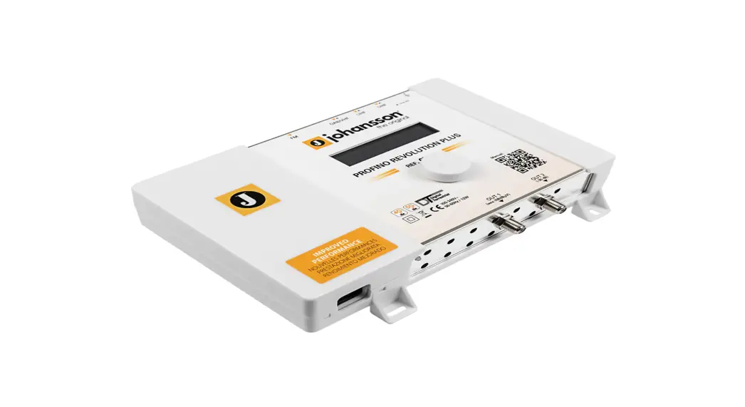
Portofino Revolution Plus SAT Ref. 6713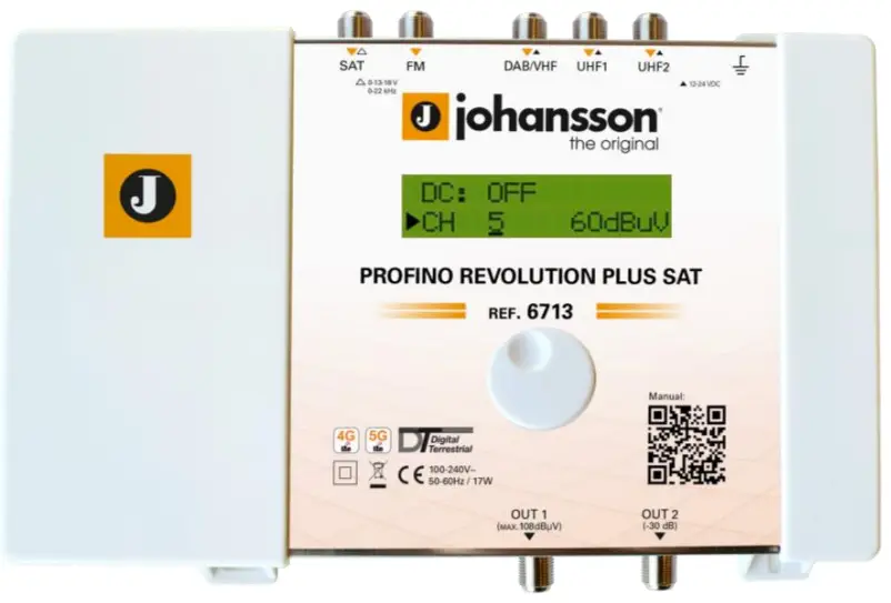
PATENTED TECHNOLOGY
SW Version 1.6.0
PORTOFINO REVOLUTION PLUS SAT (REF. 6713)
No part of this manual may be copied, reproduced, transmitted, transcribed, or translated into any language without permission. Unitron reserves the right to change the specifications of the hardware and software described in these manuals at any time. Unitron cannot be held liable for any damages resulting from the use of this product. Specifications are subject to change without notice. 06/21 © Unitron – Frankrijklaan 27 – B-8970 Poperinge – Belgium T +32 57 33 33 63 F +32 57 33 45 24 [email protected] ‘www.unitrongroup.com
INTRODUCTION
1.1. Product description
The Johansson Profino Revolution Plus SAT is an easy-to-use programmable filter amplifier for terrestrial signals. The module optimizes satellite, terrestrial VHF/UHF and FM signals from multiple inputs with the goal to provide high-quality images on your TV screen. The state-of-the-art programmable filter amplifier has no equivalent on the market due to its revolutionary technology:
- Read-out of input level strength: no need for field strength meter
- Can process and convert more than 50 channels (consisting out of 15 filters, each up to 6 MUXes wide) + SAT
- Sharpest filters on the market (50 dB on adjacent channels)
- Real-time AGC on all individual multiplexes
- Flex matrix: complete flexibility in assigning filters from any input
- Made in Europe, for worldwide application
- The Portofino Revolution Plus SAT is really easy to install
- RED compliant (selectivity classification 0 1 2 3 4)
- Equalize and optimize terrestrial and satellite signals for your optical installation (70 dBµV output power is optimal: you might use the test port (-30dB))
1.2. Typical installation
The Portofino Revolution Plus SAT can be used to provide high-quality television images (Terrestrial) and FM signals in a wide range of projects, both in the hospitality as in the residential market. Typical buildings or infrastructures where the Profino Revolution Plus SAT can be used include, but are not limited to:
- Large and small hotels, hostels, bed, and breakfasts, holiday parks
- Hospitals, rest homes, prisons, settlements
- Large and small multi-dwelling units
1.3. Package contents
- 1 Profino Revolution Plus SAT (ref. 6713)
- 1 Power Adapter Cord (180cm)
1.4. Hardware installation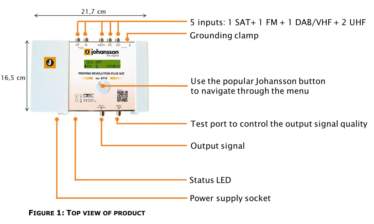
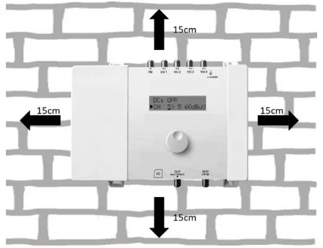
1.5. Mounting the Profino Revolution Plus SAT
- Important: Mount the module vertically to a wall in a well-ventilated room and leave a minimum space of 15 cm around the product to guarantee maximum ventilation of the product
- Connect an earth wire to the grounding clamp
- Connect the power adapter cord to the power supply socket. Check the status LED for the indication of DC power presence
- Connect the SAT, VHF, UHF, and/or FM inputs to the Profino Revolution Plus SAT
- Connect a coaxial cable to the output connector for distribution of the signal
- Connect a network analyzer to the test port to control the signal quality
- Configure the Profino Revolution Plus SAT using the rotary button, see below
- The power adapter can easily be replaced without disconnecting the product.
- To do so, open the top left plastic cover by pushing the click at the opposite side of the mains connector
1.6. Configuring the Profino Revolution Plus SAT
NAVIGATING THROUGH THE MENU
Use the Johansson rotary/push-button to navigate through the menu. This is very straightforward and simple. The table below shows how the rotary/push should be used:
 Push the button 2s to enter the basic configuration. Push the button to confirm your selections.
 When rotating the button, you scroll through the different screens.
MENU OVERVIEW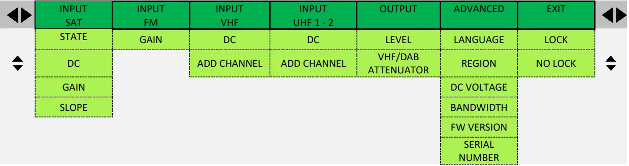
REGION/COUNTRY SETTINGS
IMPORTANT! Before starting the configuration, it is advised to set the correct region or country. Unpowered the unit, push the button and keep pushing the button while you repower the unit. Release the button when the display shows “RESET FINISHED”. Now the product is reset and will ask you to enter the country or region. This will amongst others determine the channel plan for VHF and UHF and the DC voltage for the inputs (12 or 24V).
DISPLAY READOUT
EXPLANATION To activates the correct channel frequency plan, select the country or region where the Profino Revolution Plus SAT is situated. Rotate to select and confirm by tapping the rotary button. The default setting is Europe. The Portofino Revolution Plus SAT is also operational in the following countries/regions: Australia, Brazil, China, Hongkong, Italia, New Zealand, Russia, South Africa, the UK, and the USA.
All the following menu items can be accessed without the reset procedure.
Push the rotary button for 2 seconds to access the menu
INPUT SETTINGS
| DISPLAY READOUT | EXPLANATION |
 | Tap the rotary button to enter the INPUT SAT menu. Rotate the button to navigate through the submenu. |
 | STATE: Select the state of the SAT INPUT: ON or OFF DC: Choose the voltage (13V, 13V + TONE, 18V, 18V + TONE or BYPASS) |
 | GAIN: set the satellite gain (from 20 to 40 dB) SLOPE: set the slope (from -12 to 0 dB) After INPUT SAT is configured, scroll up to the top of the menu (INPUT SAT), tap the rotary button and scroll right to INPUT FM. |
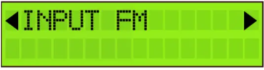 | Tap the rotary button to enter the INPUT FM menu. Rotate the button to navigate through the submenu. |
 | To filter and amplify an FM signal, tap GAIN, select the gain of the input FM signal (15 to 35 dB) and tap to confirm. Remark: DAB should be added via VHF input. |
 | After INPUT FM is configured, scroll up to the top of the menu (INPUT FM), tap the rotary button, and scroll right to INPUT VHF. Tap INPUT VHF to enter the menu to configure input 1. Rotate the rotary button to scroll down in the submenu of INPUT VHF. |
 | DC: Decide whether the input should provide power to an external amplifier. Choose between OFF or 12 V. Remark: If the external amplifier needs 24 V, you can change this in advanced settings (see further). |
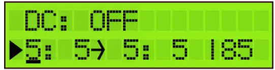 | Tap Add Channel to add the channel. Up to 6 channels can be added at once. |
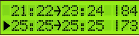
 | First, select the starting channel (e.g. CH5) and tap to confirm. Then select the stop channel (e.g. CH7, this means that you will add 3 channels). Tap to confirm. Then you can convert them using the rotary button (e.g. CH5 to CH7 converts to CH8 to CH10) and tap to confirm. |
| Some other examples: To add CH5 and convert to CH6, select as follows: 5: 5 → 6: 6 To add CH21-22-23 and convert to CH31-32-33, select as follows: 21:23 → 31:33 Remark 1: The value 85dBµV (in the bottom right corner) indicates the incoming level of the channel. Remark 2: For the EU, Italy, and New Zealand region, Channel 13 (230-240MHz) and “VHF” can be used. “VHF” means the whole band is treated in 1 bandpass filter from 174 to 240MHz. Channels “VHF” and CH13 cannot be converted. |
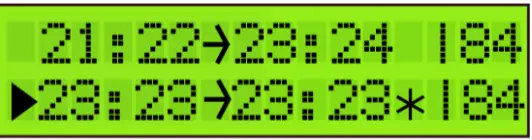 | To add another (group of) channel(s), scroll down to ADD CHANNEL and tap to confirm. To prevent bad quality or scrambled images, make sure that only one input channel is assigned to one output channel. If 2 channels are assigned to the same output channel, a star (*) will appear. |
 | The same applies to adding multiple channels. Make sure that each output channel is selected only once. |
After this, the correct LTE filter will be set for the UHF inputs (possible filters are 694MHz, 790MHz, or OFF). If the channels are lower than 48, the 694MHz filter is activated. The 790MHz filter is activated for channels lower than 60.
To delete a (group of) channel(s), position the arrow on the channel and press the rotary button for 3 seconds.
| DISPLAY READOUT | EXPLANATION |
 | To delete a (group of) channel(s), position the arrow on the channel and press the rotary button for 3 seconds. |
 | When you have added all the channels to INPUT VHF, and you want to add channels to the other inputs, scroll up to the top of the menu (to INPUT VHF), tap the button and scroll to the next input. Repeat the previous steps for all input channels. |
OUTPUT SETTINGS
| DISPLAY READOUT | EXPLANATION |
 | Define the OUTPUT LEVEL of the output signal. The range is between 88 dBµV and 108 dBµV. Check the output via a network analyzer on the -30dB test port. Note The more channels you select, the less input power you should give. |
| To compensate for cable losses, a VHF/DAB Attenuator of up to 15 dB can be set to lower the VHF and DAB output level (compared to the UHF output level). 0 dB means all channels have the same output level (see previous display readout), 15 dB means that VHF and DAB are 15 dB lower than the chosen output level above. |
Note: In the OUTPUT menu, you define the output level in dBµV of the MUXes. The Portofino Revolution Plus has enough gain to guarantee this output level under all input conditions. In case a slope has been set, the output level indicated on the display will be the output level of the highest frequency MUX.
ADVANCED SETTINGS
| DISPLAY READOUT | EXPLANATION |
 | The language of the Profiler Revolution can be set to English, Italian, Spanish or French. |
 | Tap REGION to check to which region/country the Profiler Revolution is set. To change the region/country, a hard reset is required (see instructions above (cfr. REGION/COUNTRY SETTINGS). |
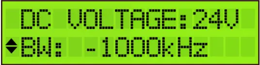 | Define DC VOLTAGE for the inputs, choose between 12V or 24V. This is a global setting for all inputs, each input can then be switched between OFF or this value. (cfr. STEP 2). All countries are set by default on 24V, except UK which is set by default on 12V. The filter bandwidth can be changed from -2000 kHz to 0 kHz in steps of 250 kHz. This allows you to optimize the bandwidth of your filter. For instance, a European 8 MHz channel can be changed from 6 to 8 MHz. The default setting is -1000 kHz, which is an optimal setting in 95% of the cases. |
 | Tap FW VERSION to check the firmware version of the device.Tap SERIAL NUMBER to check the serial number of the device. To format the SD CARD, tap FORMAT CARD. |
EXIT SETTINGS
| DISPLAY READOUT | EXPLANATION |
 | To avoid unauthorized people changing the settings, all Profiler products can be locked with a security code. |
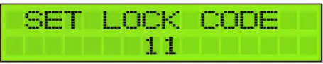 | Select LOCK and SET LOCK CODE. When the lock code is set, the device will shut down. |
 | When you restart the device, you will now have to enter the correct lock code. Remark: If you forgot the lock code, you can always use the value 50. This master code is fixed and cannot be changed. |
 | If you do not want to work with a lock code, go to EXIT and tap NO LOCK. |
TECHNICAL SPECIFICATIONS
| Portofino Revolution Plus SAT 6713 | ||
| Inputs | – | 1SAT + 1 FM + 1 DAB/VHF + 2 UHF |
| Outputs | – | 1 main (SAT-FM-DAB-VHF-UHF) + 1 test port (-30dB) |
| Frequency range | MHz MHz MHz MHz | SAT: 950 – 2400 FM: 88 – 108 VHF:174 – 240 UHF: 470 – 862 |
| LTE protection | MHz | Automatic selection: 694, 790 or OFF |
| Input level | dBµV dBµV dBµV dBµV | SAT: 40 – 95 FM: 37 – 77 VHF: 45* – 109 UHF: 45* – 109 |
| SAT output power (-35dBc/IM3 2 carriers) FM Output power (60dB/IM3) VHF/UHF Output power (60dB/IM3) VHF/UHF Output power (36dB/IM3) VHF/UHF Output power with 1 MUX VHF/UHF Output power with 15 MUX | dBµV dBµV dBµV dBµV dBµV dBµV | 119 113 115 126 108 105 |
| Gain | dB dB dB dB | SAT: 40 FM: 35 VHF: >60 UHF: >60 |
| Number of channels | – | More than 50 (15 filters) |
| Add channels | – | Per 1, 2, 3, 4, or 5 MUXes |
| Gain adjustment | dB dB – | SAT: 20 FM: 20 VHF/UHF: Channel AGC |
| Noise figure | dB | SAT: 8 |
| General attenuator | dB | 20 |
| VHF/DAB attenuator | dB | 15 |
| Slope adjustment | dB | SAT: 12 |
| Selectivity | dB dB/1 MHz | SAT: 40 (@862 MHz) VHF/UHF: 35 |
| Return loss | dB | 10 |
| Output MER | dB | VHF/UHF: >35 |
| ESD protection | – | All inputs |
| DC @ VHF/UHF input DC Load current @ VHF/UHF input | V mA | 12 or 24 100 (total for the 3 VHF/UHF inputs) |
| DC @ SAT input DC Load current @ SAT input | – mA | 13V/18V/Bypass & 0/22kHz selectable by SW 300 |
| RED compliance classes | – | 1234 |
| Operating temperature | °C | -5 to +50 |
| Power Supply | Vac | 100 – 240 |
| Power consumption | W | 17 |
| Dimensions | mm | 217 x 165 x 59 |
| Weight | kg | 0,80 |
* For 64QAM with code rate ¾
BLOCK DIAGRAM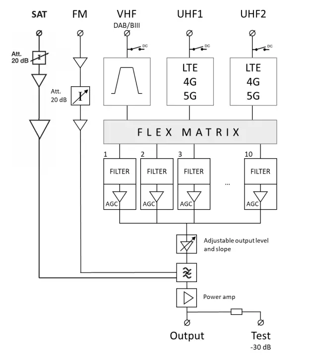
SAFETY INSTRUCTIONS
 Read these instructions carefully before connecting the unit
![]() To prevent fire, short circuit, or shock hazard:
To prevent fire, short circuit, or shock hazard:
- Do not expose the unit to rain or moisture.
- Install the unit in a dry location without infiltration or condensation of water.
- Do not expose it to dripping or splashing.
- Do not place objects filled with liquids, such as vases, on the apparatus.
- If any liquid should accidentally fall into the cabinet, disconnect the power plug.
![]() To avoid any risk of overheating:
To avoid any risk of overheating:
- Install the unit in a well-aired location and keep a minimum distance of 15 cm around the apparatus for sufficient ventilation
- Do not place any items such as newspapers, tablecloths, curtains, on the unit that might cover the ventilation holes.
- Do not place any naked flame sources, such as lighted candles, on the apparatus
- Do not install the product in a dusty place
- Use the apparatus only in moderate climates (not in tropical climates)
- Respect the minimum and maximum temperature specifications
![]() To avoid any risk of electrical shocks:
To avoid any risk of electrical shocks:
- Connect apparatus only to socket with protective earth connection.
- The mains plug shall remain readily operable
- Pull out power plug to make the different connections of cables
- To avoid electrical shock, do not open the housing of the adapter.
 Maintenance
![]() Only use a dry soft cloth to clean the cabinet.
Only use a dry soft cloth to clean the cabinet.![]() Do not use solvent
Do not use solvent![]() For repairing and servicing refer to qualified personnel.
For repairing and servicing refer to qualified personnel.![]() Dispose of according your local authority’s recycling processes
Dispose of according your local authority’s recycling processes
CONDITIONS OF WARRANTY
Unitron N.V. warrants the product as being free from defects in material and workmanship for a period of 24 months starting from the date of production indicated on it. See note below.
If during this period of warranty the product proves defective, under normal use, due to defective materials or workmanship, Unitron N.V, at its sole option, will repair or replace the product. Return the product to your local dealer for reparation.
THE WARRANTY IS APPLIED ONLY FOR DEFECTS IN MATERIAL AND WORKMANSHIP AND DOES NOT COVER DAMAGE RESULTING FROM:
- Misuse or use of the product out of its specifications,
- Installation or use in a manner inconsistent with the technical or safety standards in force in the country where the product is used,
- Use of non-suitable accessories (power supply, adapters…),
- Installation in a defective system,
- External causes beyond the control of Unitron N.V. such as drop, accidents, lightning, water, fire, improper ventilation…
THE WARRANTY IS NOT APPLIED IF
- The production date or serial number on the product is illegible, altered, deleted, or removed.
- The product has been opened or repaired by a non-authorized person.
NOTE
The date of production can be found in the product’s serial number code. The format will either be “YEAR W WEEK” (e.g., 2017W32 = the year 2017 week 32) or “YYWW” (e.g., 1732 = the year 2017 week 32).![]()
UNITRON NV
Frankrijklaan 27
B-8970 Poperinge Belgium
T +32 57 33 33 63
F +32 57 33 45 24
[email protected]
www.unitrongroup.com


