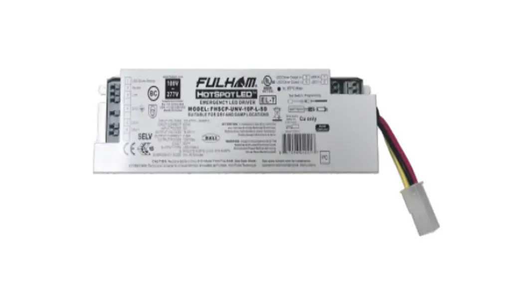
![]() FHSCP-UNV-10P-L-SD HotSpot Constant Power Programmable LED Emergency Driver
FHSCP-UNV-10P-L-SD HotSpot Constant Power Programmable LED Emergency Driver
Installation Guide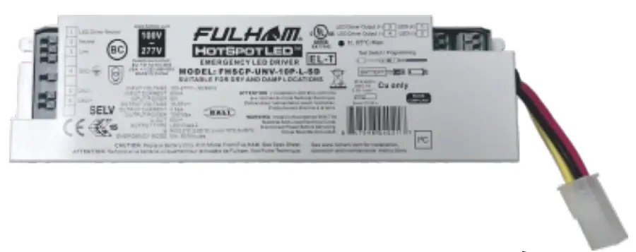 FHSCP-UNV-10P-L-SD
FHSCP-UNV-10P-L-SD HotSpot Constant Power Programmable LED Emergency Driver
GENERAL INSTALLATION GUIDELINES FOR LED EMERGENCY DRIVER
IMPORTANT SAFE PRACTICES
When using electrical equipment and this lighting device basic safety precaution should be followed at all times including but not limited to the following:
PLEASE READ CAREFULLY AND FOLLOW ALL INSTRUCTIONS FOR YOUR OWN SAFETY
IMPORTANT: Do not connect battery until fixture is installed.
IMPORTANT: An un-switched AC power source of 100VAC to 277VAC is required.
This device is designed for use in fixtures listed for dry and damp locations.
CAUTION: Make sure all electrical connections conform to the National Electrical Code and all applicable local regulations.
CAUTION: Do not let power supply cords touch hot surfaces.
CAUTION: Do not mount near gas or electric heaters.
CAUTION: Do not use outdoors.
CAUTION: Battery is rechargeable NiCd or LiFePO4 type and must be recycled or disposed of properly.
Do not use this emergency driver with accessory equipment other than recommended by manufacturer;
failure to follow this may cause an unsafe condition. Servicing should only be performed by qualified service personnel. Do not use this emergency driver for other than intended use.
CAUTION: Equipment should be mounted in locations and at heights where it will not readily be subjected to tampering by unauthorized personnel.
IMPORTANT: The output EM power will be the maximum of connected battery unless programmed to a lesser value. EM output power will not exceed the battery rating.
IMPORTANT: Indicator (LED light) illuminated indicates battery in charge mode when AC power is applied.
It is recommended and required by applicable code to test emergency function to ensure proper operation of the system; push the test switch for thirty (30) seconds every 30 days to ensure the emergency driver is functioning as LED light source illuminated. Conduct a ninety minute (90) discharge test one time (1) per year;
LED light source should be illuminated for a minimum of ninety minutes (90).
ASSEMBLY and FIELD INSTALLATION WIRING:
WARNING: AC power must be off before proceeding with assembly or installation of emergency driver.
TESTING SYSTEM: The emergency battery requires a charge minimum of one (1) hour before testing the circuit. A full charge requires twelve (12) or twenty four (24) hours (Refer to battery chart).
IMPORTANT: In order to maintain proper operation and warranty coverage, the battery must be recharged once per year prior to installation.
Fulham Head Quarters:
Fulham Co., Inc
12705 South Van Ness Ave.
Hawthorne, CA 90250
Manufacturer:
North China
Fulham Electronic Co. Ltd.
No. 9 Xingchang Road, Nanshao Zhen Changping Science Park, Beijing, P.R. China
SAVE THESE INSTRUCTIONS
Installation Instructions
A. Mounting the emergency LED driver
Note:
This driver has four mounting holes, two on each side.
Mount using all four holes or two catercorner holes. 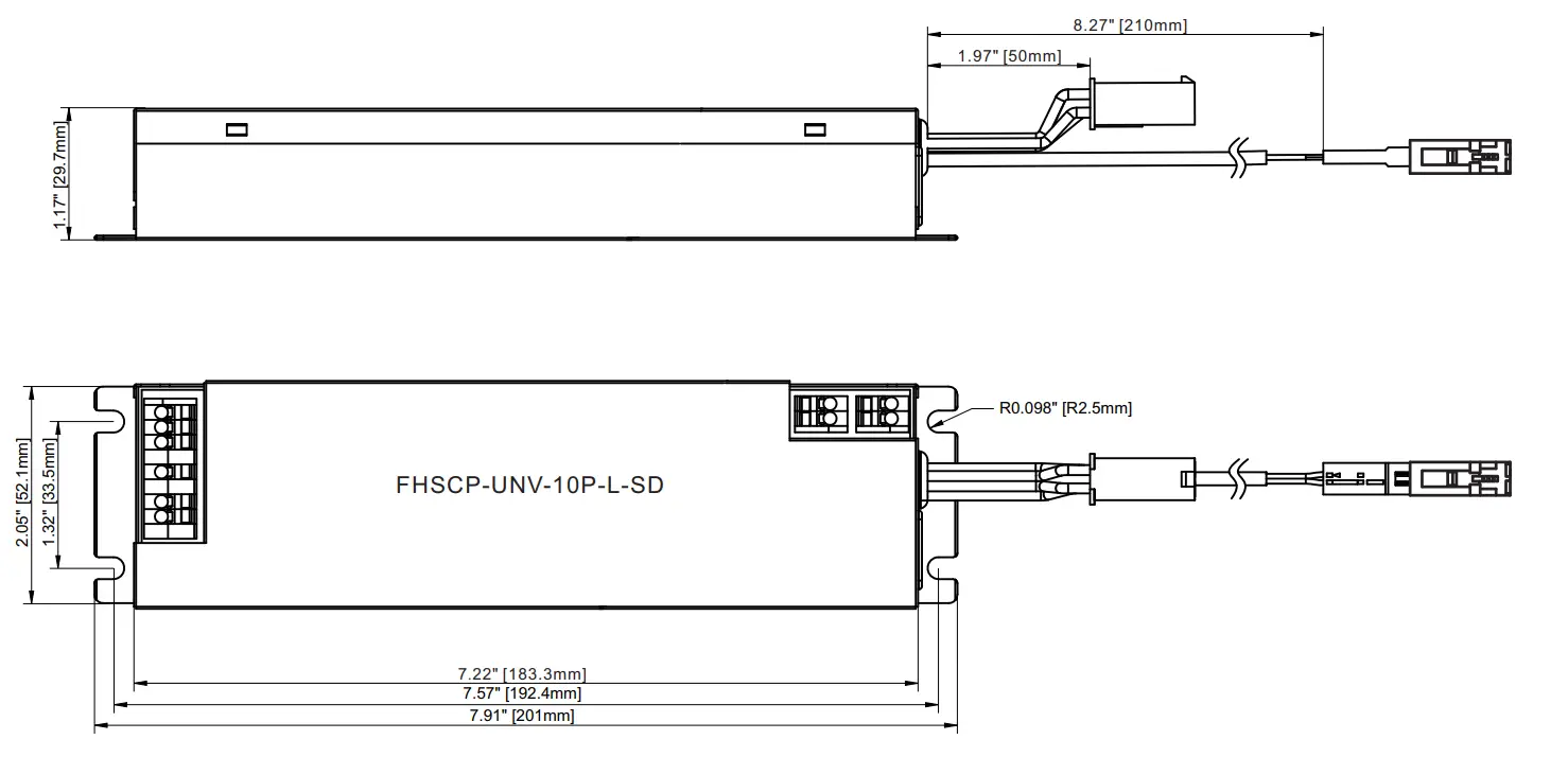
B. Making the wire connections 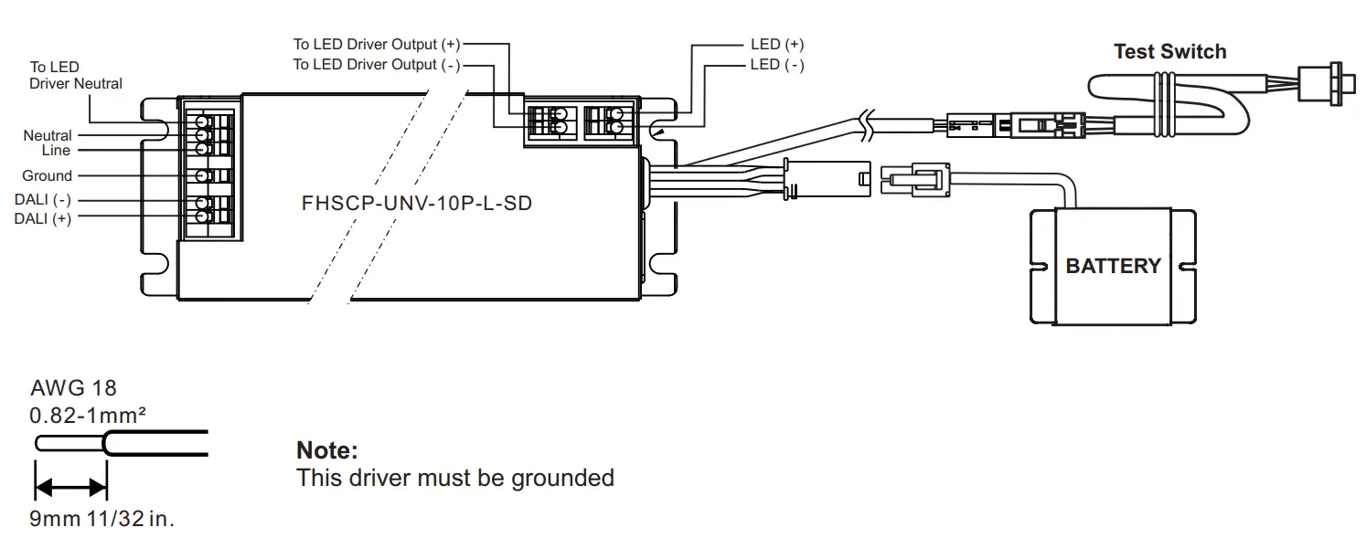 Wiring Diagram 1
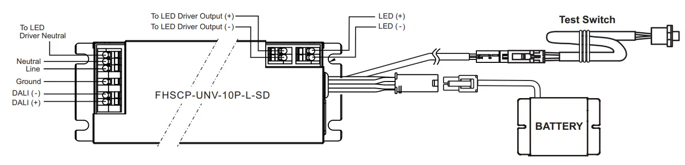
One (1) LED Array Normal Operation / Emergency
NOTE: Drill or punch a ½” (12.7mm) dia. hole in mounting plate to insert the test switch.
| Wire Harness | Length (Inches) |
| Test Switch | 8.27” |
| Battery Conn. | 1.97” |
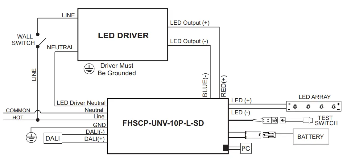
Wiring Diagram 2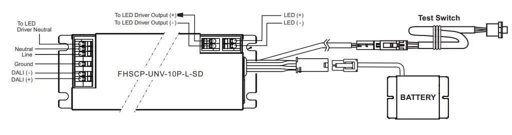 Series Wiring: Two (2) LED Arrays, One (1) LED Array in Emergency
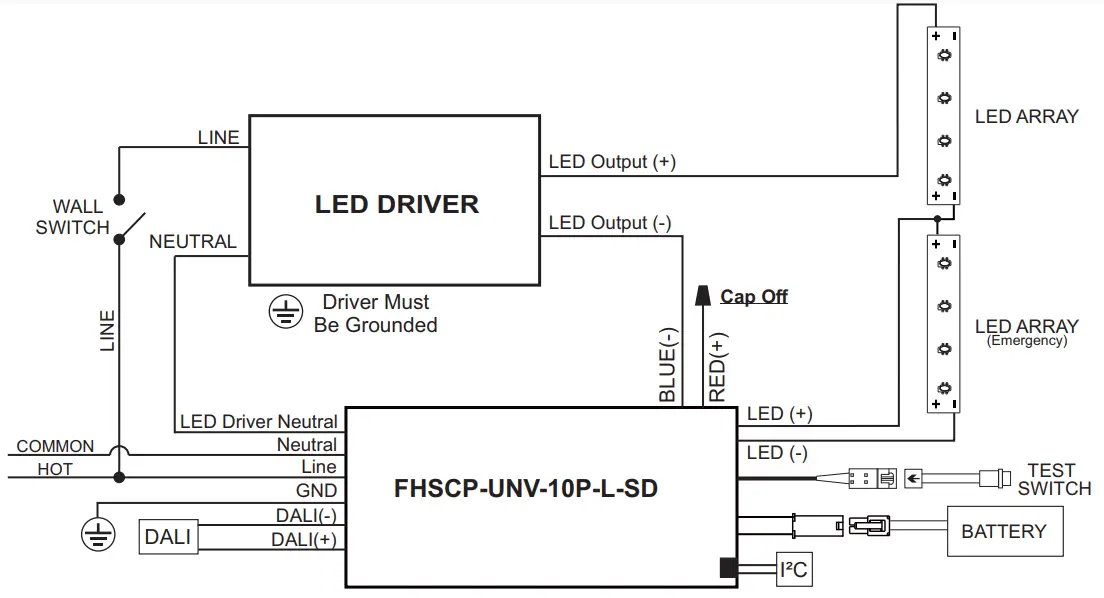
| Wire Harness | Length (Inches) |
| Test Switch | 8.27” |
| Battery Conn. | 1.97” |
NOTE: Drill or punch a ½” (12.7mm) dia. hole in mounting plate to insert the test switch.
Wiring Diagram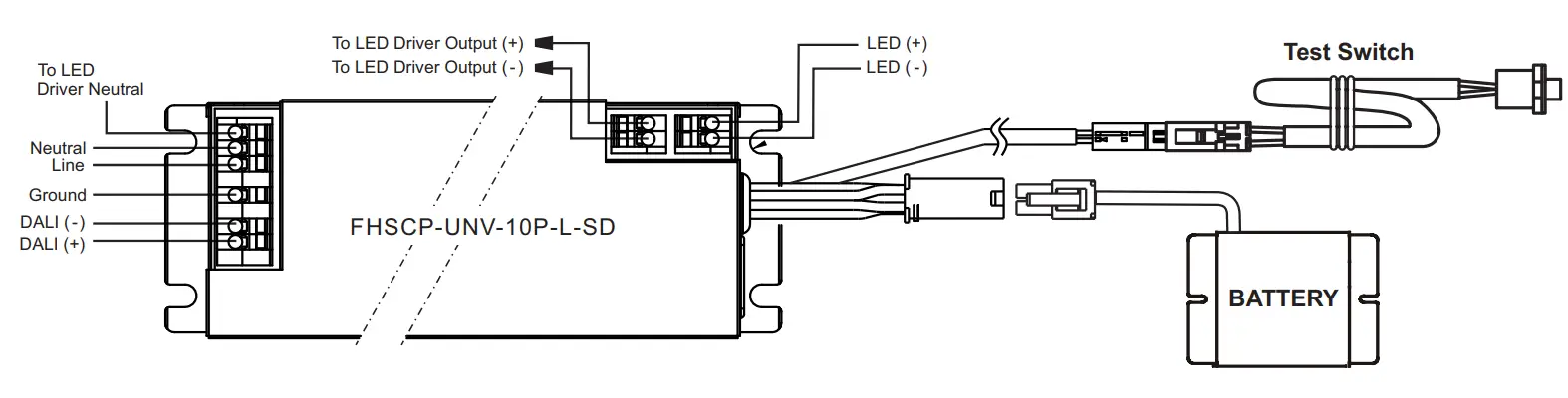
One (1) LED Array in Normal Operation, One (1) LED Array in Emergency 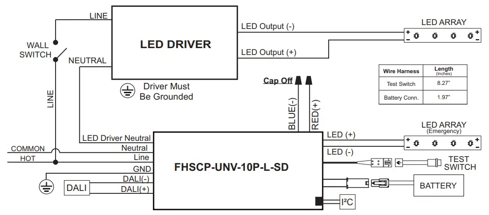 NOTE: Drill or punch a ½” (12.7mm) dia. hole in mounting plate to insert the test switch.
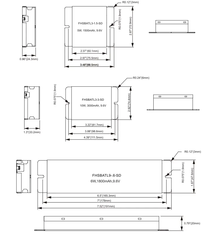
Battery Chart
| Fulham Model No. | Chemistry | RoHS | Pack Capacity | Max Load for 90 min. | Battery Voltage | Recharge Time | Battery Dimensions |
| FHSBATL3-1.5-SD | LiFePO4 | Compliant | 1500mAh | 5W | 9.6V | 12Hrs | 3.48” x 2.87”x 0.96” (88.5 x 72.9 x 24.3mm) |
| FHSBATL3-3-SD | LiFePO4 | Compliant | 3000mAh | 10W | 9.6V | 12Hrs | 4.39” x 2.92” x 1.3” (111.5 x 74.4 x 33.2mm) |
| FHSBATL9-.6-SD | LiFePO4 | Compliant | 1800mAh | 6W | 9.6V | 12Hrs | 7.52” x 1.87” x 0.79” (191 x 47.6 x 20mm) |
| FHSBATL6-1.5L-D | LiFePO4 | Compliant | 3000mAh | 10W | 9.6V | 12Hrs | 9.13” x 1.63” x 0.97” (232 x 41.4 x 24.7mm) |
| FHSBATT8-C3L-SD | NiCd | Exempt | 3000mAh | 10W | 9.6V | 24Hrs | 9.25” x 2.11” x 1.21” (235 x 53.5 x 30.7mm) |
CAUTION: Replace battery only with corresponding part number.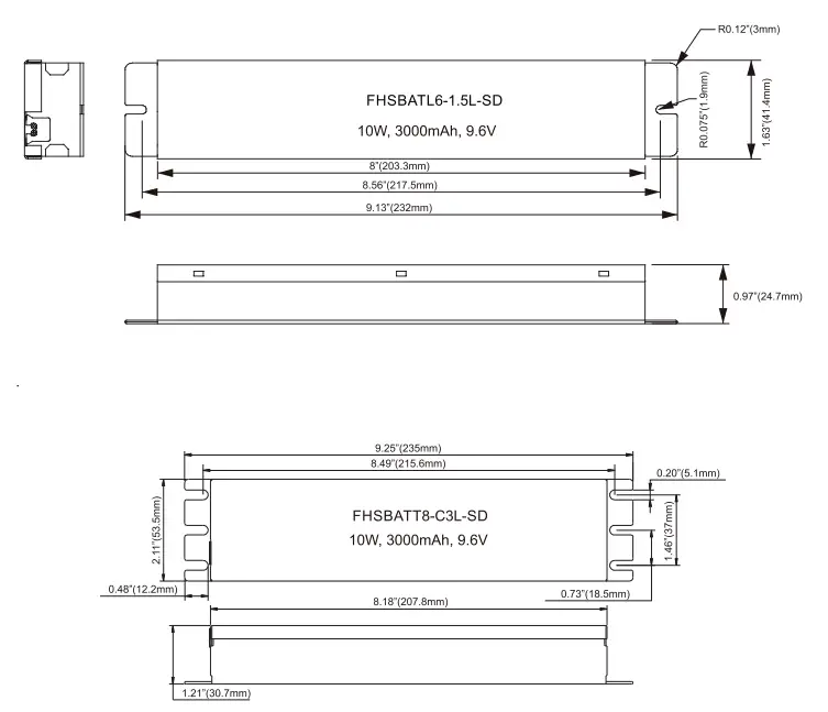
Battery Dimensions
Guideline On Calculating Emergency Illumination Level
The purpose of this guideline is to identify the illumination level of the LED luminaire when used with Fulham’s FHSCP-UNV-10P-L-SD LED emergency driver. The path of egress illumination level during emergency operation is determined by types of luminaires, Luminaire Efficacy, Luminaire Mounting Height, Emergency Power and some
other effects in real application.
Step 1: Select an LED Luminaire, and make sure the LED light source is electrically compatible with Fulham’s LED emergency driver. Get the Light Distribution data (usually an .ies file) and Rated Efficacy data (lumen per watt) from luminaire supplier.
If the luminaire is DesignLights ConsortiumTM (DLC) compliant, you can also get the efficacy information from DLC website.
– Open DLC Qualified Product List(QPL) database search page: https://www.designlights.org/search/
– Searching keywords by model, brand name or manufacturer for the luminaire used.
– Find the “Efficacy” data listed on website or calculated by dividing “Light output” by “Wattage”, the efficacy value should be shown in lumen per watt (lm/W).
If the luminaire is ENERGY STAR compliant, you can also get the luminaire efficacy information from ENERGY
STAR website.
– Open ENERGY STAR certified Light Fixtures database search page: https://www.energystar.gov/productfinder/product/certified-light-fixtures/results
– Searching keywords by model, brand name or manufacturer for the luminaire used.
– Find the “Energy Efficiency” data listed on website. If it is showed as “Measured at the Source”, please contact with luminaire supplier for additional light loss for this light source inside the fixture. The value should be shown in lumen per watt (lm/W).
Step 2: Determine the Emergency Power and calculate the Emergency Light Output.
FHSCP-UNV-10P-L-SD is programmable output; setting a proper Emergency Power is vital to achieve desired illumination.
Emergency Light Output is equal to the Emergency Power multiply by luminaire efficacy. For example, if the luminaire is 120lm/W and in 3W emergency operation, the total Emergency Light Output is 120lm/W * 3W = 360lm.
Step 3: Use industry lighting design software to calculate the illumination level according to the luminaire layout in room, luminaire mounting height, the original .ies file and Emergency Light Output calculated above. If the illumination level cannot meet life safety codes, go back to Step2 to use a higher Emergency Power or go back to Step1 to select a higher efficacy luminaire or use more luminaires in the room.
Fulham’s FHSCP-UNV-10P-L-SD LED emergency driver is compliant with UL 924 standard, according to UL test data, Table 1 and Table 2 below give basic indication to determine the min. Emergency Power and Luminaire Max.
Mounting Height for 1 foot-candle illumination based on a single luminaire with typical Lambertian distribution. It is the light designer/ construction contractor’s responsibility to validate the real illumination level on site, to assure the emergency light illumination level is in accordance with the requirement of Federal, state and local municipal codes. It may diff to the theoretical calculation or simulation on computer.
Table 1. Min. EM Power for 1fc @ 10ft vs. Luminaire Efficacy
| Luminaire Efficacy (ImNV) glib | Min. EM Power to achieve 1 fc @ 10ft Mounting Height |
| 80 | 5.0 W |
| 100 | 4.0 W |
| 120 | 3.3 W |
| 140 | 2.8 W |
| 160 | 2.5 W |
| 180 | 2.2 W |
Table 2. Max. Mounting Height vs. Luminaire Efficacy
| Luminaire Efficacy (Ina/VV) | EM 3W | Max. Mounting Height EM 5W | for 1fc EM 10W |
| 80 | 8.1 ft | 10.1 ft | 13.9ft |
| 100 | 8.9 ft | 11.2 ft | 15.4 ft |
| 120 | 9.6 ft | 12.1 ft | 16.8 ft |
| 140 | 10.3 ft | 13.0 ft | 18.1 ft |
| 160 | 10.9 ft | 13.9ft | 19.3 ft |
| 180 | 11.5 ft | 14.6 ft | 20.4 ft |
Test Switch Indicator Status:
| LED Indicator Status | EM Driver Status/Mode |
| • Solid Green | System OK/AC OK. |
| • Slow Flashing Red, 4s On/1s Off | Battery not detected, check battery switch or connection. |
| • Flashing Red, 1s On/1s Off | Battery failure, replace battery. |
| • Flashing Green, 2s On/2s Off | DALI duration test underway. |
| • Fast Flashing Red, 0.1s On/0.1s Off | Open / Short Circuit, Check LED load. |
| • Slow Flashing Red, 0.1s On/3s Off | Normal working in EM mode. |
Test Switch Operations:
- EM Test: Press and hold the test button to enter EM mode for testing, in all normal AC powered situations including low power standby modes.
- DALI Duration Test: Quickly press the test button three times within 1 second to enter the DALI duration test.
To quit the DALI duration test, hold the test button for 10 seconds.
DALI Duration Test & Function Test:
- Duration time: 90 Min.
- Function time: 1 Min.
- Duration time by manual entry: 90 Min.
- Duration test and function time: Only test 1 time
- Duration test: test switch or DALI controller
- Duration test and function test interval time setting: Only by DALI controller
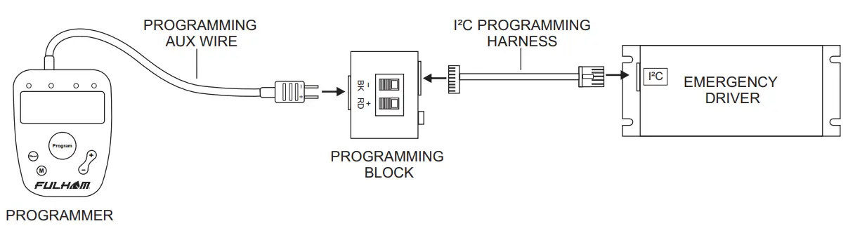
Programming
The FHSCP-UNV-10P-L-SD is programmed through the I²C port on the emergency driver with the TPSB-100 programmer.
Unless otherwise programmed the output will self-program to the maximum rating of the battery.
Customer must use the I²C programming harness and programming block that comes with the TPSB-100.
Programming Wire Diagram
Programming Features
Output EM Power – 3W to 10W
Enable / Disable Self-Diagnosic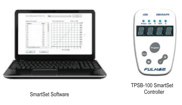 * For more detailed programming instructions please see our Programming Instructions and Design Guide found on our website:
https://www.fulham.com/PDFs/SpecSheets/Fulham-Design-Guide-Programmable-Drivers.pdf
![]() Fulham Co. Inc.: 12705 South Van Ness Ave.
Fulham Co. Inc.: 12705 South Van Ness Ave.
Hawthorne, CA 90250 Tel.: 1-323-779-2980
Fax.: 1-323-754-9060.
Specifications subject to change without notice.
www.fulham.com
2020-850 Rev C![]()


