![]()
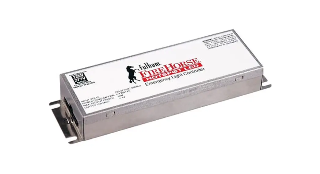
FHS2-UNV-36L
INSTALLATION INSTRUCTIONS

FHS2-UNV-36L HotSpot2 LED Emergency System
- Emergency LED Driver
- Universal Voltage: 100-277VAC, 50/60Hz
- Output Wattage: 1.2-20W
- Output Current range of 100mA – 700mA
- Output voltage range of 12-55VDC
This Driver Will Operate The Following LED Modules: Any LED module designed to accept an input voltage range of 12-55VDC and can operate up to a current of 700mA.
General Specifications
| Input Voltage Input Current Input Power Red Lead White/Black Lead Standby Input Power Driver Type Output Current Output Voltage Range Output Power Number of Output Channels RFI/EMI Output Type Battery Type Battery Capacity Available Battery Recharge Time Battery Discharge Time Test Switch Remote Mounting Distance Wire Length Ambient Operating Temperature Range Input Surge Protection Protections Service Life Approvals / Class | 100-277VAC, 50/60Hz 0.1A Max. 6W Max. 3A,60V Max. 1A Max. <0.8W Constant Current 100mA -700mA Initial (Refer to accesory chart) 12-55VDC 20W Max 1 Channel FCC Part 15 Class A LED Class 2 NiCd 9.6VDC or LiFePO4 9.6VDC 900mAh, 1000mAh, 1200mAh, 1500mAh, 1800mAh, 3000mAh, 4000mAh, 6000mAh 24-32 Hours (Refer To Battery chart) 90 Minutes Min. 20′ (6m) Max. Input: 18AWG, Output: 22AWG, Red Lead: 18WG, Test Switch: 22AWG, Battery: 22AWG NiCd: 0°C to 50°C (32°F to 122°F), LiFePO4: 10°C to 50°C (50°F to 122°F) FHSBATCC3-3: -20°C to 50°C (-4°F to 122°F) FHS2-UNV-36L: -20°C to 50°C (-4°F to 122°F) 2.5KV Ring Wave Battery Over Discharge Protection Output Short Circuit Protection 50,000 hours RoHS , cURus 1310 , cURus 924 , CEC Title 20, Dry and Damp Locations, CE, EN61347-2-7:2012 EN61347-1:2015, EN55015:2013 +A1:2005, EN61000-3-2:2014, EN61000-3-3:2013, EN61547:2009 |
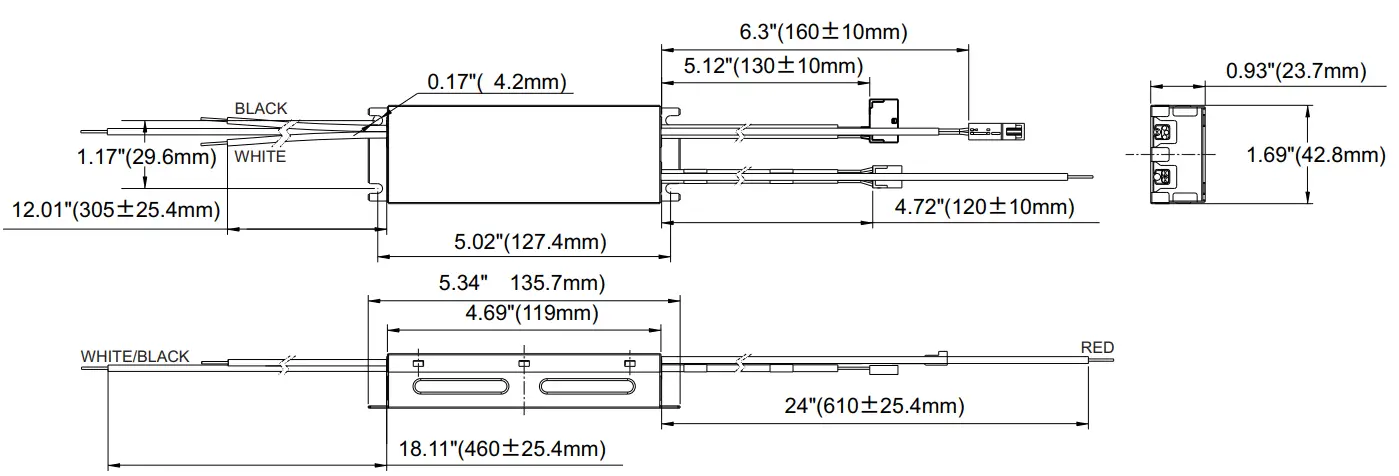
Mechanical Data
Important and Safety Instructions
When using electrical equipment and this lighting device basic safety precaution should be followed at all times including but not limited to the following:
PLEASE READ CAREFULLY AND FOLLOW ALL INSTRUCTIONS FOR YOUR OWN SAFETY
- IMPORTANT: Do not connect battery until fixture is installed.
- IMPORTANT: An un-switched AC power source of 100VAC to 277VAC is required.
- This device is designed for use in fixtures listed for dry and damp locations.
- CAUTION: Make sure all electrical connections conform to the National Electrical Code and all applicable local regulations.
- CAUTION: Do not let power supply cords touch hot surfaces.
- CAUTION: Do not mount near gas or electric heaters.
- CAUTION: Battery is rechargeable Ni-Cd or LiFePO4 type and must be recycled or disposed of properly.
Do not use this emergency driver with accessory equipment other than recommended by manufacturer; failure to follow this may cause an unsafe condition. Servicing should only be performed by qualified service personnel.
Do not use this emergency driver for other than intended use.
Not suitable for high-risk task area lighting.
Equipment should be mounted in locations and at heights where it will not readily be subjected to tampering by unauthorized personnel.
IMPORTANT: The output EM power will not exceed the max power rating of the battery.
IMPORTANT: Indicator (LED light) illuminated indicates battery in charge mode when AC power is applied.
It is recommended and required by applicable code to test emergency ballast to ensure proper function of the system; push the test switch for thirty (30) seconds every thirty (30) days to ensure the emergency driver is functioning by illuminating the light source. Conduct a ninety (90) minutes discharge test one (1) time per year; LED light source should be illuminated for a minimum of ninety (90) minutes .
ASSEMBLY and FIELD INSTALLATION WIRING: WARNING: AC power must be off before proceeding with assembly or installation of emergency driver.
TESTING SYSTEM: The emergency battery requires a charge minimum of one (1) hour before testing the circuit. A full charge requires twenty four (24) or thirty two (32) hours, depending upon battery pack. Please refer to battery chart for charging time.
IMPORTANT: In order to maintain proper operation and warranty coverage, the battery must be recharged once per year prior to installation.
| Fulham Head Quarters: Fulham Co., Inc 12705 South Van Ness Ave. | Manufacturer: North China Fulham Electronic Co. Ltd. No. 9 Xingchang Road, Nanshao Zhen Changping Science Park, Beijing, P.R. China |
SAVE THESE INSTRUCTIONS
Wiring Diagrams 1
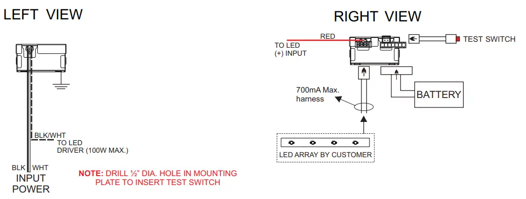
Wiring Diagram (TYP)
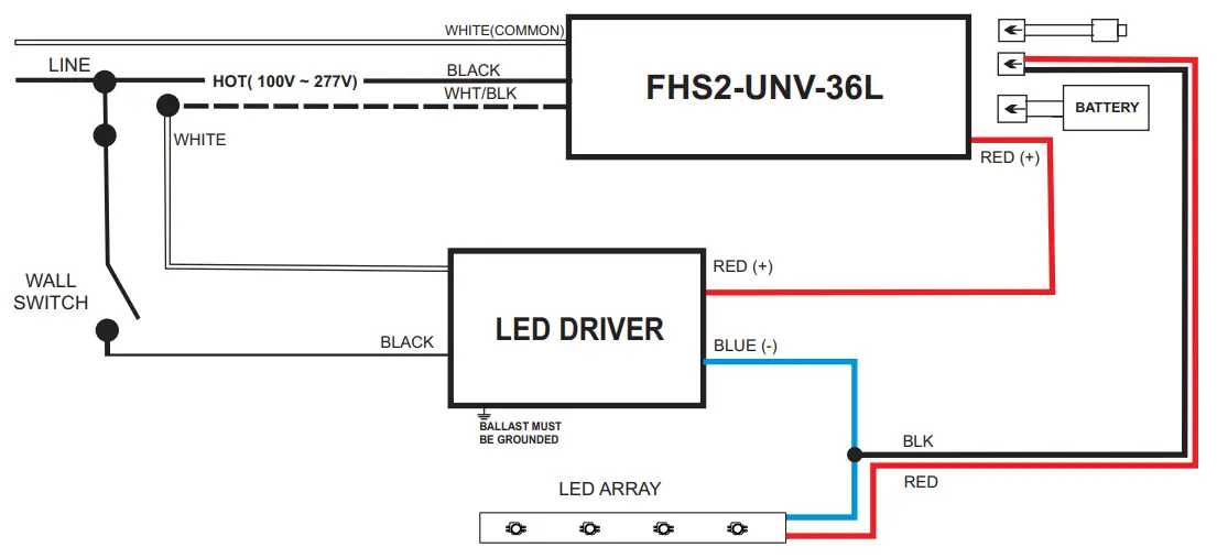
WIRING DIAGRAM (EMERGENCY ONLY)
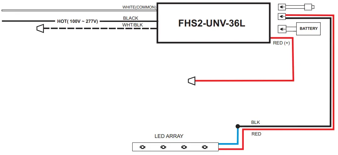
Input
| Wire Color | Length (Inches) |
| Black | 12.01” ±1” |
| White | 12.01” ±1” |
| Black / White | 18.11” ±1” |
Output
| Wire Color | Length (Inches) |
| Red | 24” ±1” |
| Test Switch | 5.12” ±0.4” |
| Output Harness | 4.72” ±0.4” |
| Battery Conn. | 5.12” ±0.4” |
Battery Chart
| Fulham Model No. | Chemistry | Compliant | Pack Capacity | Max Load for 90 min. | Battery Voltage | Battery Count | Recharge Time | Dimensions (LxW x H) | 12″ Harness (Optional) | Mounting Accessory (Included / Optional) |
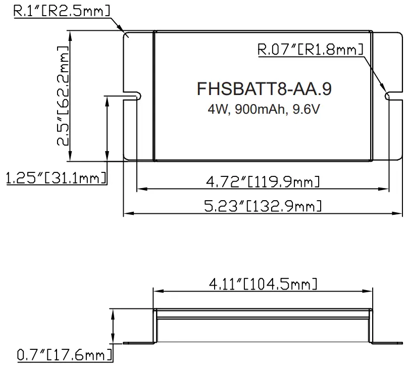
| FHSBATT8-AA.9 | NiCd | 900mAh | 4W | 9.6V | 8 Cells | 24Hrs | 5.23″ x 2.5″ x 0.7″ | FHS-EXTM | Bracket Included | |
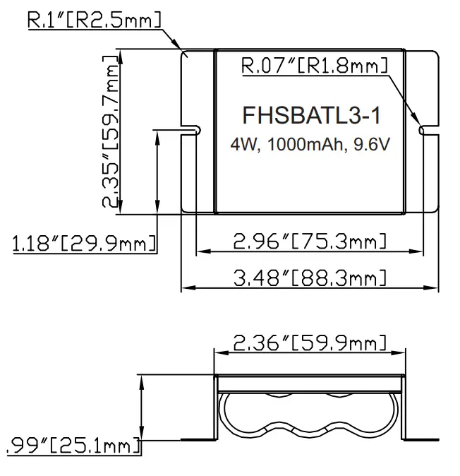
| FHSBATL3-1 | LiFePO4 | RoHS | 1000mAh | 4W | 3 Cells | 24Hrs | 3.48″ x 2.35″ x 0.99″ | |||
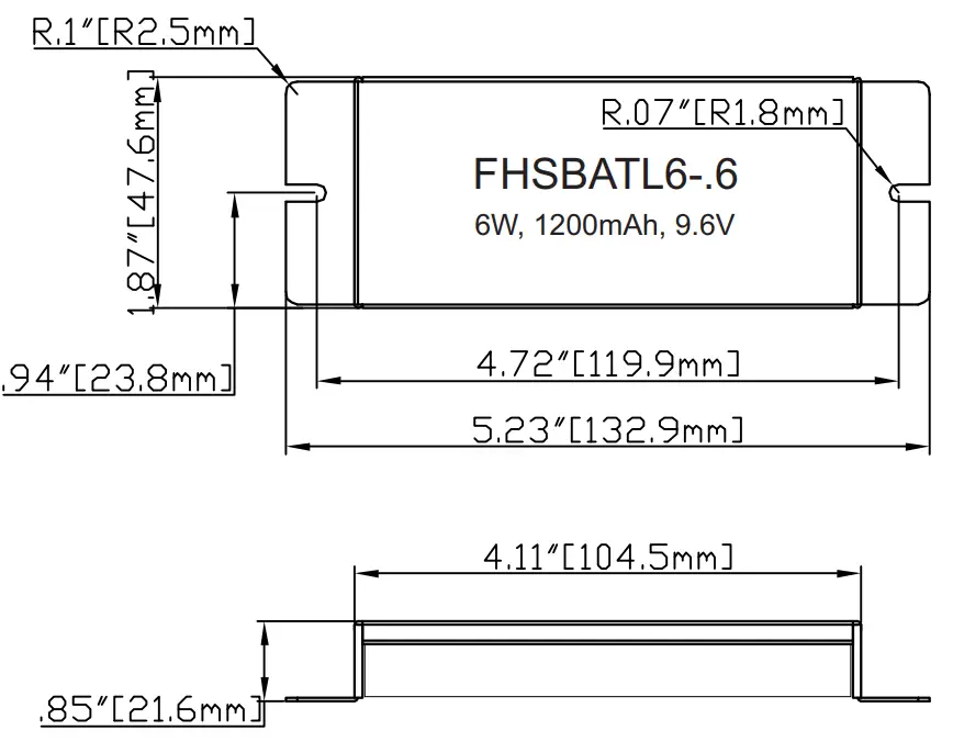
| FHSBATL6-.6 | LiFePO4 | RoHS | 1200mAh | 6W | 6 Cells | 24Hrs | 5.23″ x 1.87″ x 0.85″ | |||
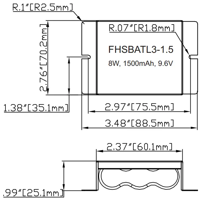
| FHSBATL3-1.5 | LiFePO4 | RoHS | 1500mAh | 8W | 3 Cells | 24Hrs | 3.48 “x 2.76″ x 0.99” | |||
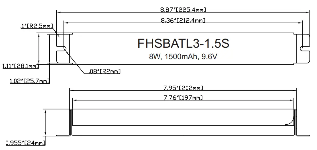
| FHSBATL3-1.5S | LiFePO4 | RoHS | 1500mAh | 8W | 3 Cells | 24Hrs | 8.87″ x 1.11″ x 0.955″ | |||
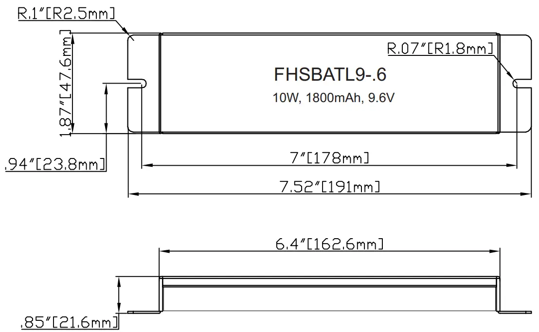
| FHSBATL9-.6 | LiFePO4 | RoHS | 1800mAh | 10W | 9 Cells | 24Hrs | 7.52″ x 1.87″ x 0.85″ | |||
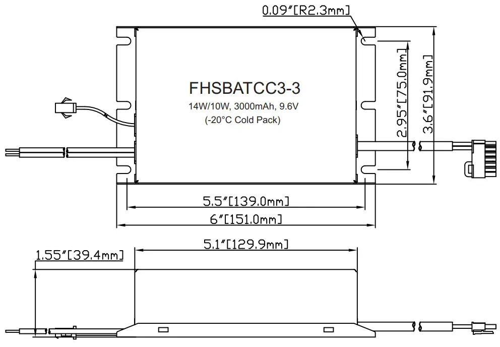
| FHSBATCC3-3 (-20°C Cold Pack) | LiFePO4 | RoHS | 3000mAh | 14W/10W” | 3 Cells | 24Hrs | 6″ x 3.6″ x 1.55″ | |||
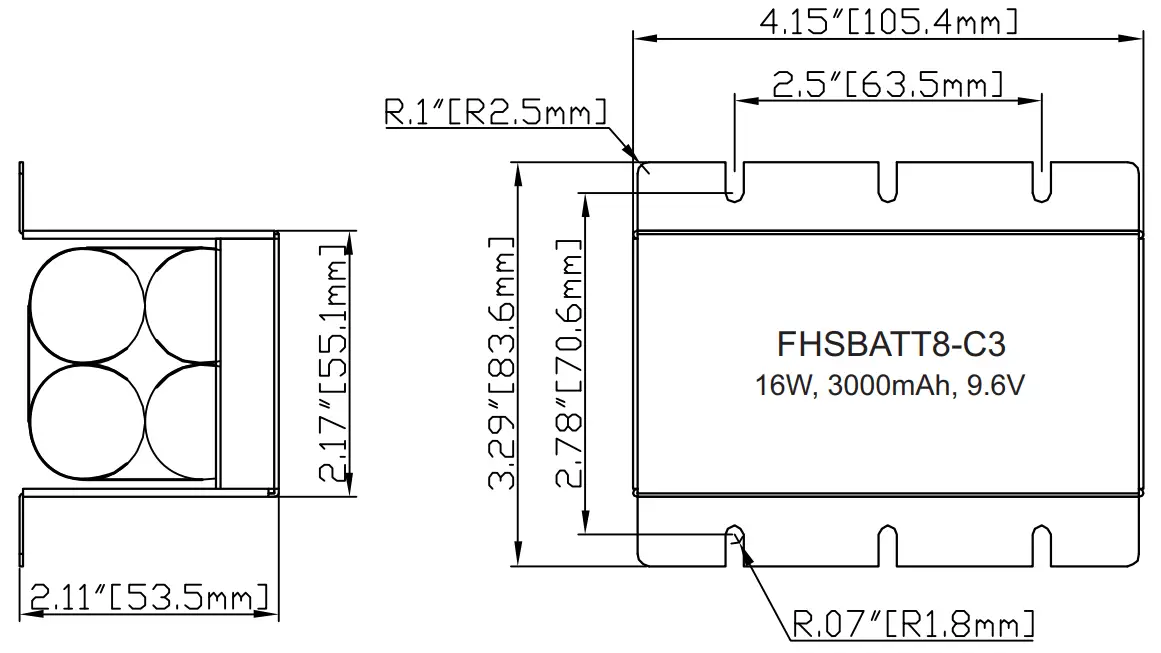
| FHSBATT8-C3 | NiCd | 3000mAh | 16W | 8 Cells | 24Hrs | 4.15″ x 3.29″ x 2.11″ | ||||
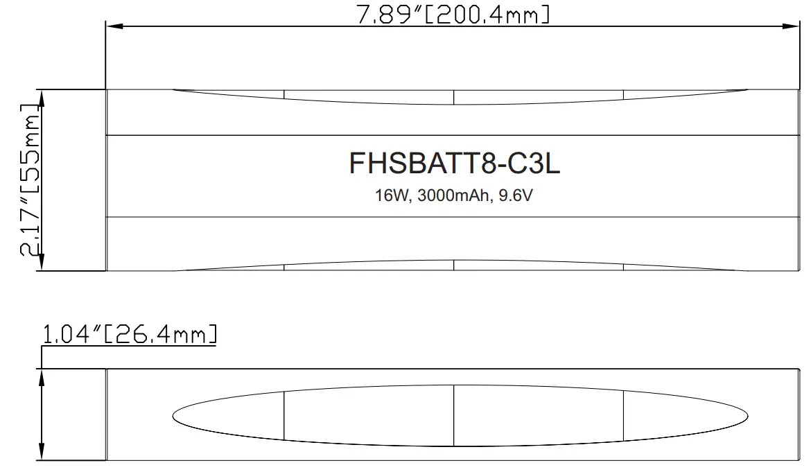
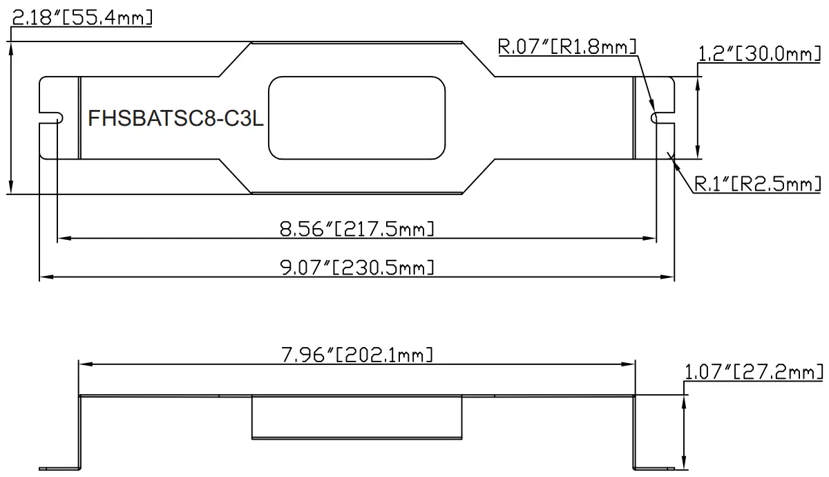
| FHSBATT8-C3L` | NiCd | 3000mAh | 16W | 8 Cells | 24Hrs | 7.89″ x 2.17″ x 1.04″ | FHSBATSC8-C3L | |||
| FHSBATL3-3 | LiFePO4 | RoHS | 3000mAh | 16W | 3 Cells | 24Hrs | 4.39″ x 2.82″ x 1.3″ | Bracket Included | ||
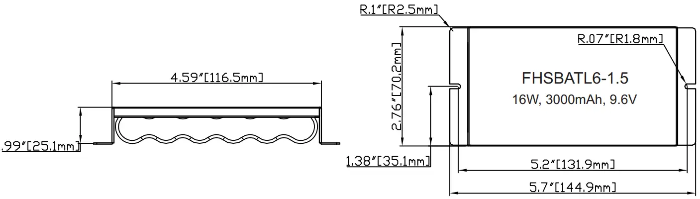
| FHSBATL6-1.5 | LiFePO4 | RoHS | 3000mAh | 16W | 6 Cells | 24Hrs | 5.7″ x 2.76″ x 0.99″ | |||
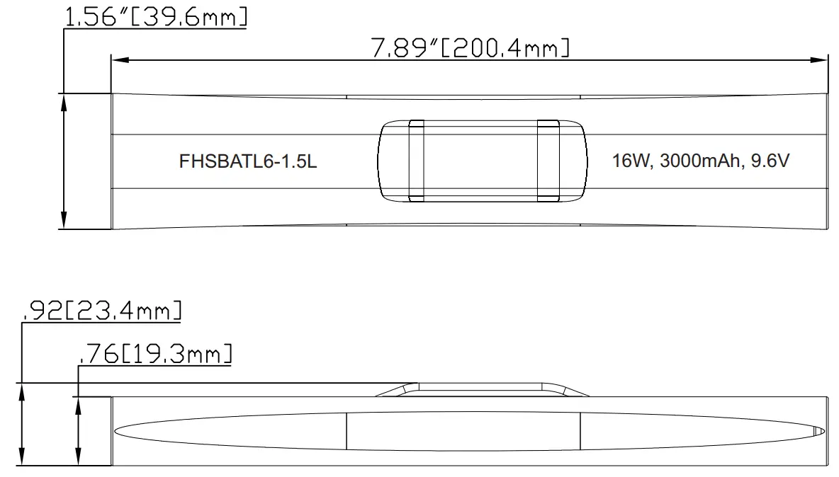
| FHSBATL6-1.51: | LiFePO4 | RoHS | 3000mAh | 16W | 6 Cells | 24Hrs | 7.89″ x 1.56″ x 0.92″ | FHSBATSC6-1.5L | ||
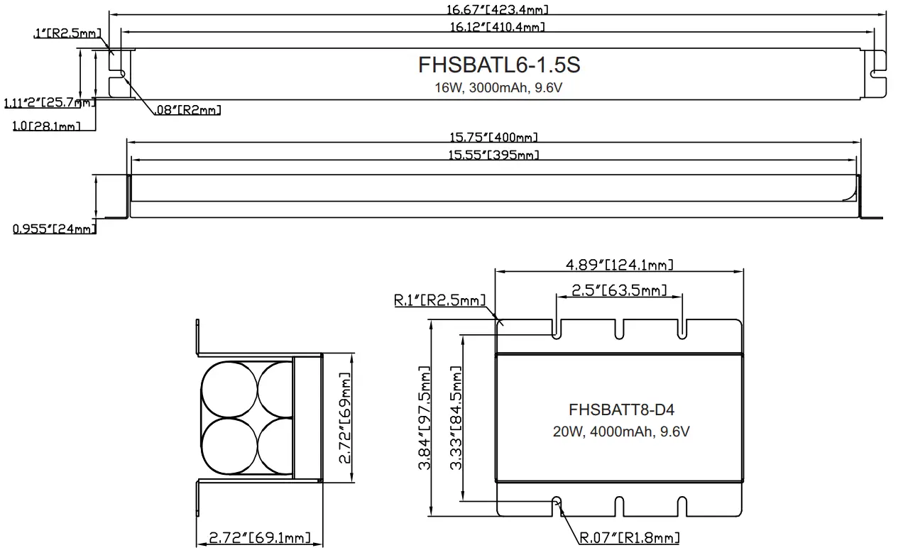
| FHSBATL6-1.5S | LiFePO4 | RoHS | 3000mAh | 16W | 6 Cells | 24Hrs | 16.67″ x 1.11″ x 0.955″ | Bracket Included | ||
| FHSBATT8-D4 | NiCd | 4000mAh | 20W | 8 Cells | 24Hrs | 4.89″ x 3.84″ x 2.72″ | ||||
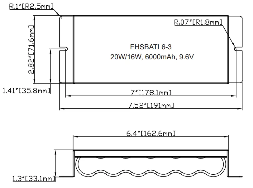
| FHSBATL6-3 | LiFePO4 | RoHS | 6000mAh | 20W/16W” | 6 Cells | 32Hrs | 7.52″ x 2.82″ x 1.3″ | |||
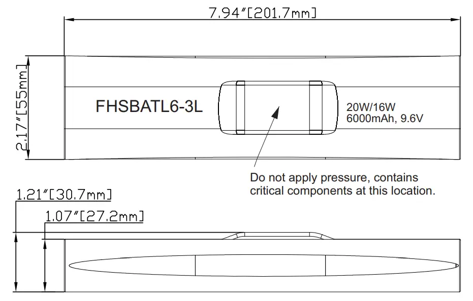
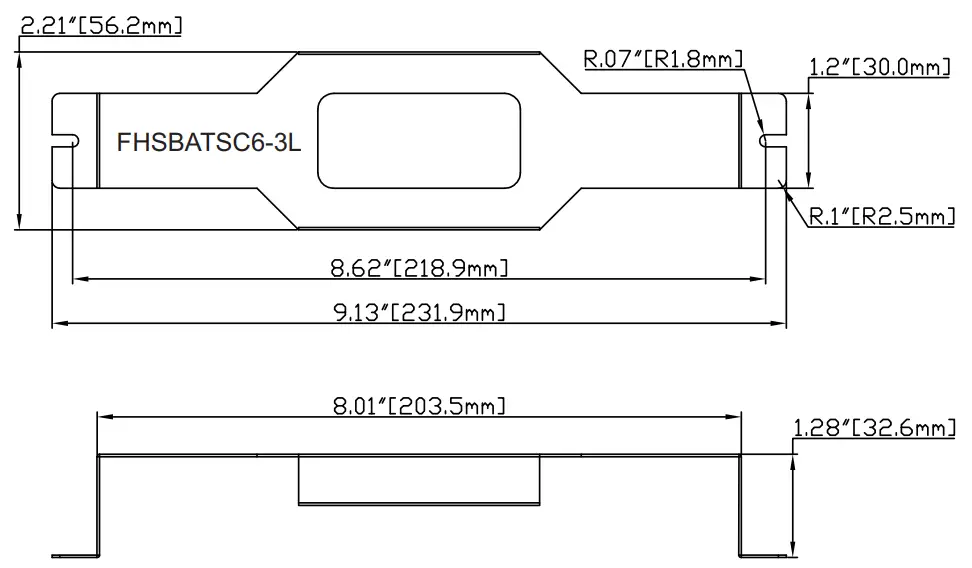
| FHSBATL6-312 | LiFePO4 | RoHS | 6000mAh | 20W/16W” | 6 Cells | 32Hrs | 7.94″ x 2.17″ x 1.21″ | FHSBATSC6-3L |
CAUTION: Replace battery only with corresponding part number.
*Note: These batteries do not include mounting means, separate mounting brackets are available.
**Note: This battery rating applies for Canada use only.
| Accessory Harness (Wire length 24″) | |||
| Part Number | Description | Part Number | Description |
| FHS-HARNESS-100 | 100 mALED Harness | FHS-HARNESS-125 | 125 mALED Harness |
| FHS-HARNESS-150 | 150 mALED Harness | FHS-HARNESS-175 | 175 mALED Harness |
| FHS-HARNESS-200 | 200 mALED Harness | FHS-HARNESS-225 | 225 mALED Harness |
| FHS-HARNESS-250 | 250 mALED Harness | FHS-HARNESS-300 | 300 mALED Harness |
| FHS-HARNESS-350 | 350 mALED Harness | FHS-HARNESS-400 | 400 mALED Harness |
| FHS-HARNESS-450 | 450 mALED Harness | FHS-HARNESS-500 | 500 mALED Harness |
| FHS-HARNESS-550 | 550 mALED Harness | FHS-HARNESS-600 | 600 mALED Harness |
| FHS-HARNESS-650 | 650 mALED Harness | FHS-HARNESS-700 | 700 mALED Harness |
Battery Dimensions
Battery Dimensions
Mounting Bracket Dimensions (Optional)
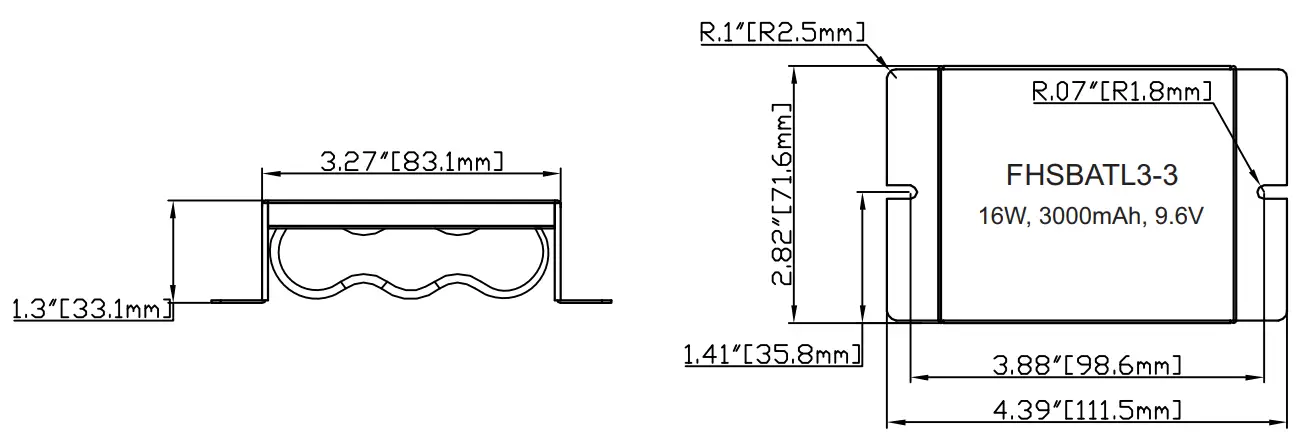
Battery Dimensions
Mounting Bracket Dimensions (Optional)
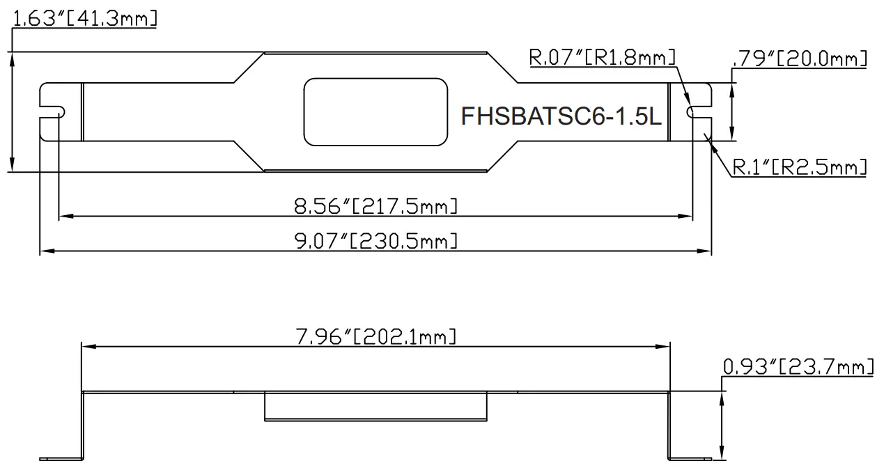
Mounting Bracket Dimensions (Optional)
TEST SWITCH INDICATOR STATUS:
| Indicators Type | LED Indicators Status | EM Driver Status/Mode |
| Bi-Color Indicator | ● Solid Green | ystem OK/AC OK (Self-diagnostic Enabled or Disabled). |
| Single Color Indicator | ● Solid RED ON | |
| Bi-Color Indicator | ● Flashing Green, 0.1s on/3s off | System OK / EM Mode |
| Single Color Indicator | ● Flashing RED, 0.1s on/3s off | |
| Bi-Color Indicator | ● Slow Flashing Red, 4s on/1s off | Battery not detected, check battery switch or connection. |
| Single Color Indicator | ● Slow Flashing Red, 4s on/1s off | |
| Bi-Color Indicator | ● Flashing Red, 1s on/1s off | Replace battery. |
| Single Color Indicator | ● Flashing Red, 1s on/1s off | |
| Bi-Color Indicator | ● Flashing Green, 2s on/2s off | Self-Diagnostic test underway. |
| Single Color Indicator | ● Flashing Red, 2s on/2s off | |
| Bi-Color Indicator | ● Fast Flashing Red, 0.1s on/0.1s off | Abnormal driver performance, replace driver. |
| Single Color Indicator | ● Fast Flashing Red, 0.1s on/0.1s off | |
| Bi-Color Indicator | ● Very Slow Flashing Red, 1s on/7s off | Over temperature. |
| Single Color Indicator | ● Very Slow Flashing Red, 1s on/7s off | |
| Bi-Color Indicator | ● Very Slow Flashing Red, 4s on/4s off | LED output load is Short/Over Current/Over Voltage/Open Circuit in EM Mode. |
| Single Color Indicator | ● Very Slow Flashing Red, 4s on/4s off |
TEST SWITCH OPERATIONS:
- EM Test: Press and hold test button (>1s)to enter EM mode for testing in normal AC powered .
- Manual Self-Diagnostic: After charging twelve (12) hours or battery fully charged, quickly press the test button three times within two seconds to force the controller to enter a Self-Diagnostic cycle. To quit the self-diagnostic cycle after engaged press and hold the test button for ten seconds.
- Enable/Disable Auto Self-Diagnostic: Press and hold the test button for one second, then release and quickly press the test button two times, then release and press and hold the test button for two seconds. When properly executed the indicator on the test button will display the appropriate color for the Enable/Disable status. A flashing of 2.5s ON/0.5s OFF means “Enabled”, while a flashing of 0.5s ON/2.5s off means “Disabled”. Once Enable/Disable is set the status color on the test button will remain the same throughout normal operation (refer to Indicator Status Table).
- Enable/Disable Self-Diagnostic Status: Fast click 2 times within 2s to query the Self-Diagnostic Enabled/Disabled status. The indicator would blink for current status for 3 cycles. 2.5s ON/0.5s OFF stands for Enabled. 0.5s ON/2.5s OFF stands for Disabled.
- Exit Output Short Circuit/No Load/Over Voltage Protection: When the test button flashes red for 4s on/4s off, press and hold the test switch for 10 seconds.
- Turn off EM output: Press and hold the test switch for 10 seconds during EM output condition to turn off EM output. This is useful for production environment to turn off the EM output once a luminaire has completed functionality testing. This applies to products with Serial Number starting with Date code: S12016 or higher.
Programming:
Unless otherwise programmed the output will self-program to the rated output of the harness. This driver can be programmed using Fulham SmartSet TPSB-100 or TPSM-100E. Programming features include the following:
- Enable/Disable Self-Diagnostic
- Output EM Current : 0mA,100-700mA
* When programmed to 0mA; output current defaults to rating of output harness(Refer to accessory harness chart).
Fulham extends a limited warranty to the original purchaser or first user for a period of 5 years from the date of manufacture when properly installed and operated under normal conditions of use. For complete terms and conditions, please refer to the Warranty Center at www.fulham.com.
Specifications subject to change without notice.


