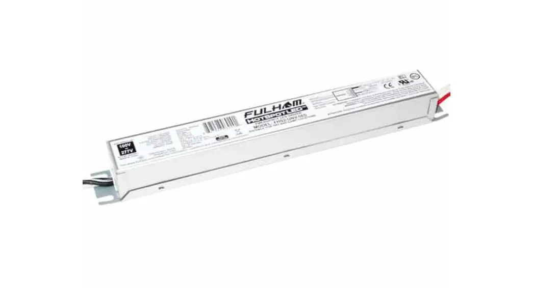
![]() UNV-10P-S-SD Programmable Emergency LED Driver
UNV-10P-S-SD Programmable Emergency LED Driver
Instruction Manual
Programmable Emergency LED Driver
- Emergency LED Driver
- Universal Voltage: 120-277V~
- Output Voltage Range: 15-55V
- Output Current: 55-666mA
- Output Wattage: 3W-10W (Factory default 10W)
- Output Type: LED Class 2, Class 2
- Number of Output Channels: 1 Channel
General Specifications
| Input Current | 0.1A Max |
| Input Voltage / Frequency | 120-277V~, 50/60Hz |
| Input Power | 5W Max |
| Standby Input Power | <0.85W |
| Input Power Pass-Through Rating (AC Driver Line) | 2A |
| Output Type | LED Class 2,Class 2 |
| Output Power | 3W-10W |
| Voltage Range | 15-55V |
| Current Rated | 15-55V |
| Number of Output Channels | 55-666mA |
| Program Port | 1Channel |
| Input Surge Protection | I²C |
| Protections | Line – Neutral 1kV, Line & Neutral – Ground 2kV and 3KV or 6KV Ring Wave |
| Protections | Output Open Protection Output Overload Protection Output Short Circuit Protection Output Temperature Protection |
| Emergency Mode | 90 Minutes Min |
| RFI/EMI | FCC Part15A EN55015 |
| Ambient Operating Temperature Rang | 10°C To 55°C (50°F To 131F°) (>7W) |
| Sound Rating | 0°C To 55°C (32°F To 131F°) (≤7W) A |
| Battery Type | Lithium |
| Battery Voltage | 11.1V |
| Pack Capacity | 2400mAh |
| Battery Rating | 25.92Wh |
| Battery Count | 3 Cells |
| Battery Recharge Time | 12 Hours |
| Battery Discharge Time | Min 1.5 Hours |
| Test Switch Remote Mounting Distance | 20′ (6m) Max. |
| Service Life | 50,000 hours |
| Warranty | 5 years |
| Safety Standard | UL924, CSA C22.2 No.141-10/cUL EN61347-1, EN61347-2-7, EN62384, EN60598-2-22, EN50172 CEC, MSDS, DGM EEE C62.41.2-2002 EN61000-3-2, EN61000-3-3, EN61000-4-2, EN61000-4-3, EN61000-4-4 EN61000-4-5, EN61000-4-6, EN61000-4-8, EN61000-4-11, EN61000-4-29 |
Mechanical Data
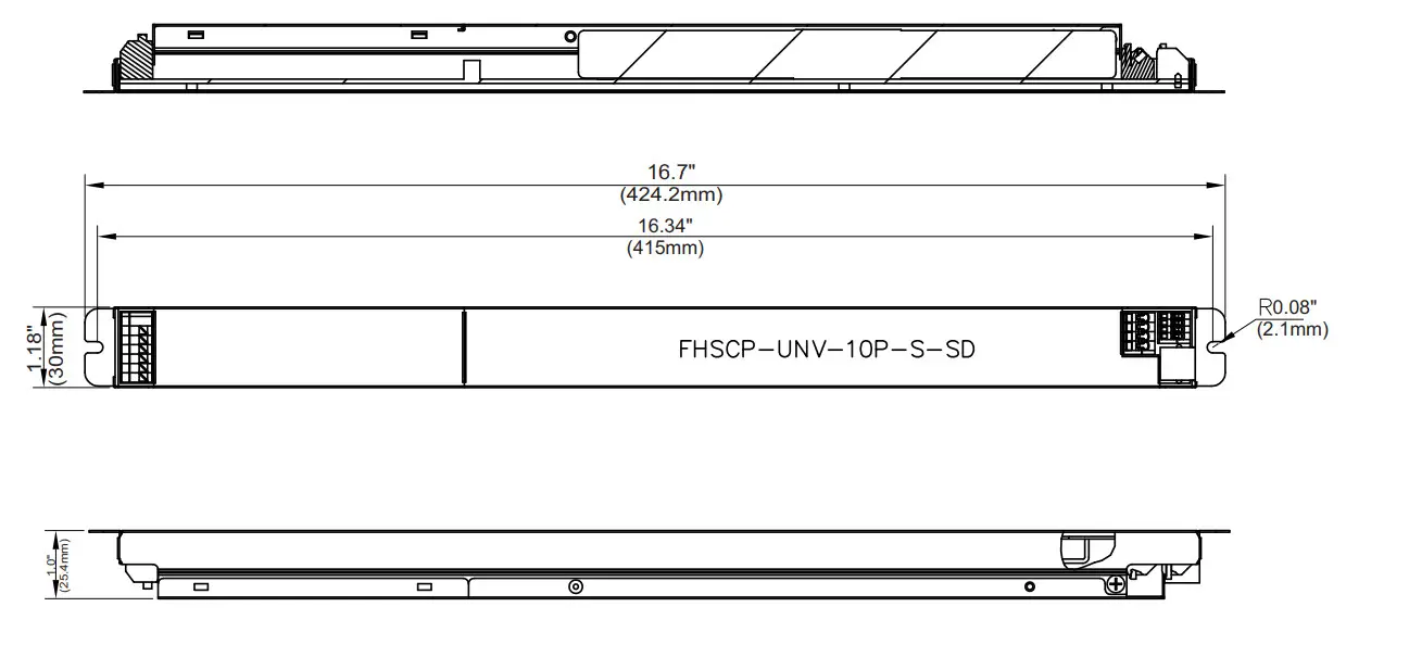
Overall Dimension
| Length | 16.7″ (424.2mm) |
| Width | 1.18″ (30mm) |
| Height | 1.0″ (25.4mm) |
Accessories
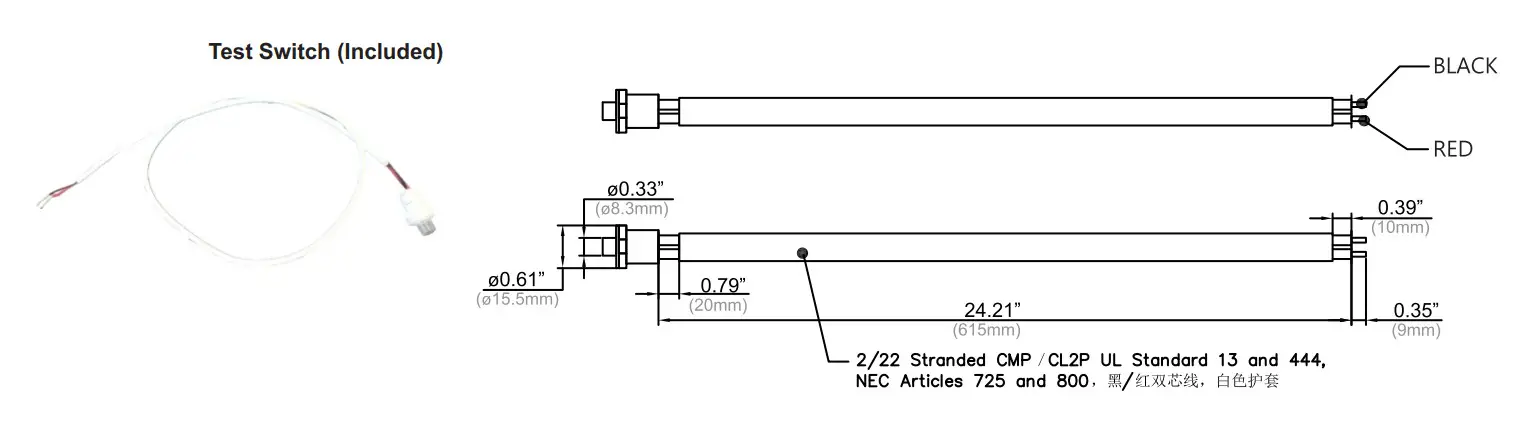
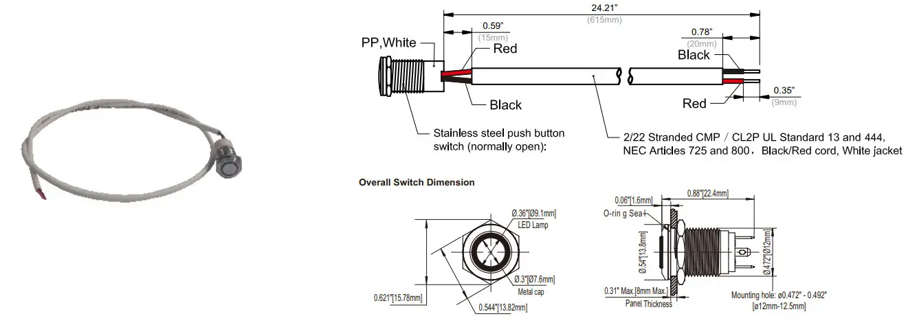
Wet Location Test Switch: FHS-TSTWL-BC (Optional)
Wall Plate: FHSWLPWH
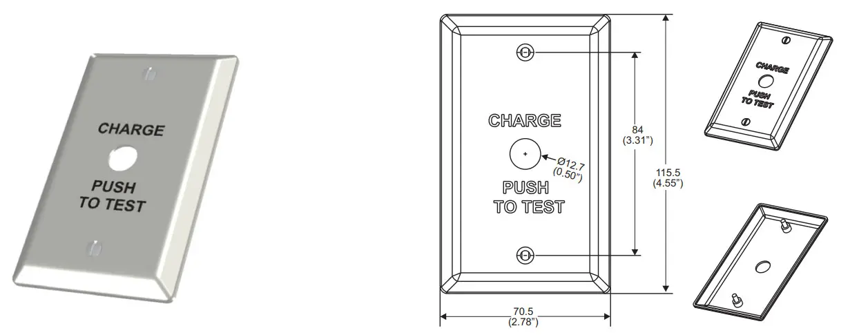 | |
| Wall plate and screw color: white with black lettering | 1.“Charge push to Test”plate 2. (2) 6-32 x ½”LG mounting screws |
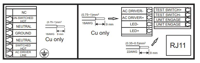
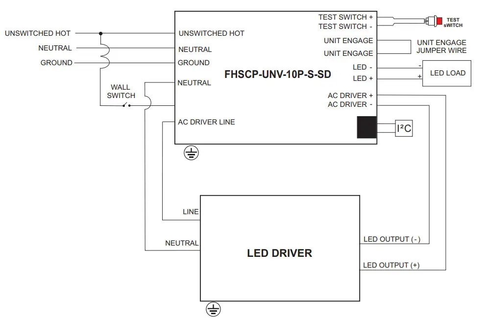
Wiring Diagram
TOP VIEW
SELF-DIAGNOSTIC INSTRUCTIONS! OPERATION:
If the self-diagnostic feature is enabled: The emergency LED driver will conduct a self-check for thirty(30)seconds every thirty(30)days; and a ninety(90) minutes self-check every 12 months. After every self-check the LED indicator light will indicate a status signal. Check indicator status chart above to diagnose the status signal.
If the self-diagnostic feature Is disabled: User must conduct a manual test every thirty (30) days to ensure the emergency LED light source illuminates as intended. A full discharge test shall be conducted once a year: the LED light source shall illuminate for a minimum of ninety (90) minutes.
*Self Diagnostic feature is factory enabled
TEST SWITCH INDICATOR STATUS:
| LED Indicators Status | EM Driver Status! Mode |
| System OK / AC OK (Self-Diagnostic Enabled or Disabled) | |
| Battery NOT detected, check battery switch or connection | |
| Battery Failure, replace battery | |
| Self-Diagnostic test underway | |
| Abnormal driver performance, replace driver | |
| Normal working in EM mode | |
| No load or output over voltage protection triggered. Check LED connection | |
| Charge circuit failure replace driver |
TEST SWITCH OPERATIONS
EM Test: Press and hold the test button (>1s) to enter EM mode in normal AC powered.
Manual Self-Diagnostic: After charging twelve (12) hours or battery fully charged, quickly press the test button three(3) times within two (2) seconds to force the controller to enter Self-Diagnostic cycle. To quit the Self-Diagnostic cycle after engaged, press and hold the test button for ten (10) seconds.
Enable/Disable Self-Diagnostic Status: Fast click 2 times within 2s to query the Self-Diagnostic Enabled/Disabled status. The indicator would blink for current status for 3 cycles. 2.5s ON/0.5s OFF stands for Enabled. 0.5s ON/2.5sOFF stands for Disabled.
Load Test: When the test button is flashing red 4s orU4s off. press and hold the test switch for 10s, the unit will enter Self -Diagnostic mode.
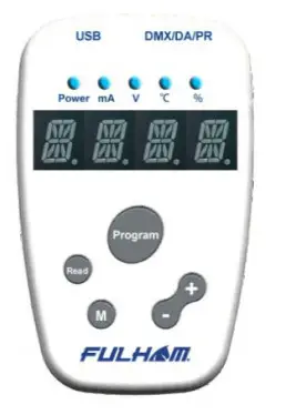
Programming:
Unless otherwise programmed the output will self-program to the maximum rating of the battery. This EM driver can be programmed using the Fulham Smart Set TPSB100(E). Programming features include the following:
*Output EM power – 3w to 10w
*Enable/Disable Self- Diagnostic
* For more detailed programming instructions please see our Programming Instructions and Design Guide found on our website:
https://www.fulham.com/PDFs/SpecSheets/Fulham-Design-Guide-Programmable-Drivers.pdf
Guidelines
- Driver must be grounded by means of the Driver case.
Over temperature protection
- The Fulham Hotspot Plus LED drivers are protected against thermal overload. If the temperature limit is exceeded, the output current is reduced.
LED load
- Fulham Hotspot Plus LED drivers are designed to drive passive LEDs, -COB’s and -LED assemblies Proper function is not guaranteed when (LED) loads with active components are used.
Mounting / Cooling
- Above an output power of 20W, the driver needs to be mounted on a heat conductive surface of at least 200cm². Always test if the surface is sucient enough before installing the driver.
Short-circuit protection
- In case of a short circuit the LED driver switches to protection mode. After the removal of the short-circuit the LED driver will recover automatically.
No-load Operation
- In no-load operation the output voltage will not exceed the specified open circuit output voltage.
Hot Swapping
- This driver does not support hot swapping of the LEDs
- Remote Mounting
- Up to 15ft with 18AWG. Contact Fulham for higher remote distance.
Battery Maintenance
- In order to maintain proper operation and warranty coverage, the battery must be recharged once per year prior to installation.
Warranty
- Reference Fulham’s limited Warranty: https://cdn.fulham.com/PDFs/Limited-Warranty.pdf
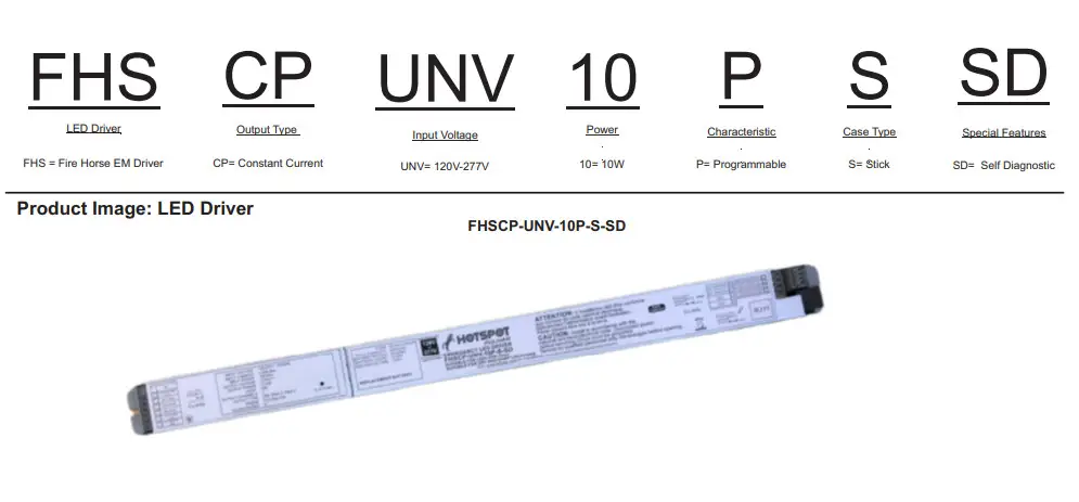
Part Number Matrix
Packaging
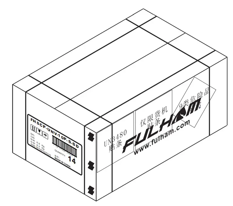
OUTER DIMENSION
| L | W | H |
| 19.84” (504mm) | 9.21”(234mm) | 8.86”(225mm) |
| Net Weight | Gross Weight | QUANTITY |
| 15.21lbs. (6.9kg.) | 18.30lbs. (8.3kg) | 14pcs. |
![]() Fulham Co. Inc.: 12705 South Van Ness Ave., Hawthorne, CA 90250
Fulham Co. Inc.: 12705 South Van Ness Ave., Hawthorne, CA 90250
Tel.: 1-323-779-2980 Fax.: 1-323-754-9060.
Specifications subject to change without notice.
[email protected]
www.fulham.com
2020-858 Rev B![]()


