Edgecor E AS5710-54X 54 Port 10G Fiber Ethernet Switch User Guide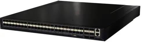
Unpack the Switch and Check Contents
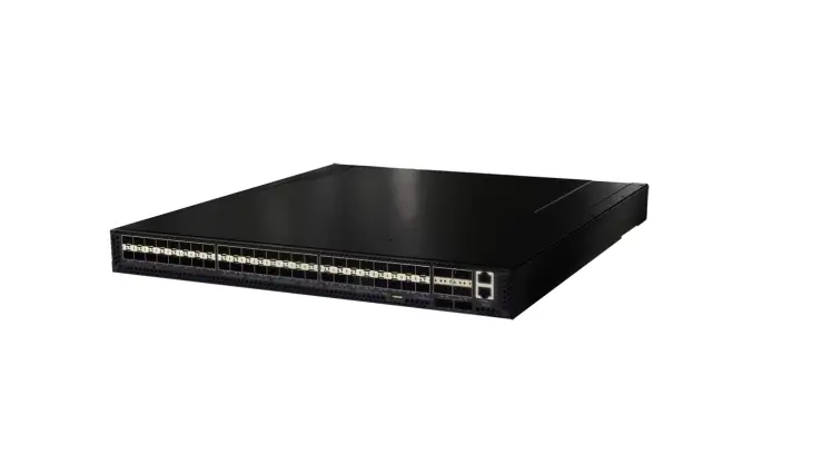
AS5710-54X, AS5712-54X or AS5812-54X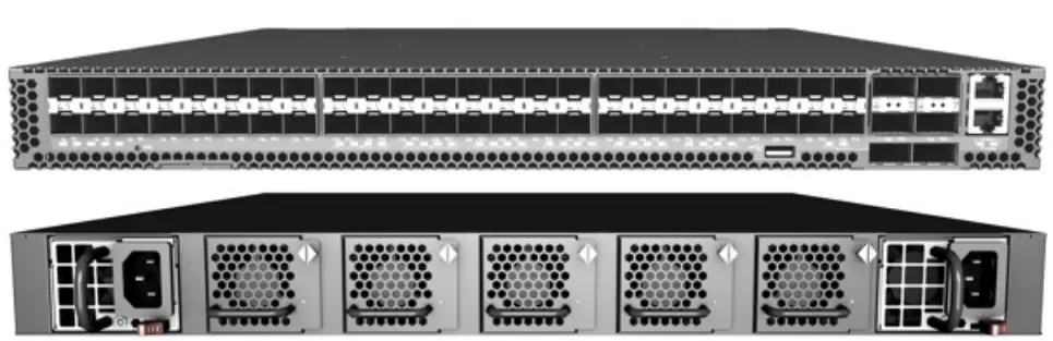
![]()
Rack Mounting Kit —2 front-post brackets, 2 rear-post brackets, 20 screws, and 2 ear-locking screws.
Power Cord (included with AC PSUs only).
![]()
Ground Wire (included with DC PSUs only)
Console Cable RJ-45 to DB-9
![]()
DC Power Cable (included with 48 VDC PSU only).

Documentation Quick Start Guide (this document) and Safety and Regulatory Information.
![]() Warning: For a safe and reliable installation, use only the accessories and screws provided with the A55710-54X, A55712-54LA55812-54X. Use of other accessories and screws could result in damage to the unit. Any damages incurred by using unapproved accessories are not covered by the warranty.
Warning: For a safe and reliable installation, use only the accessories and screws provided with the A55710-54X, A55712-54LA55812-54X. Use of other accessories and screws could result in damage to the unit. Any damages incurred by using unapproved accessories are not covered by the warranty.
![]() Caution: The switch includes plug-in power supply (PSU) and fan tray modules that are installed into its chassis. All installed modules must have a matching airflow direction. That is, if the installed power modules have a front-to-back (F2B) airflow direction, all the installed fan tray modules must also have a F2B airflow direction.
Caution: The switch includes plug-in power supply (PSU) and fan tray modules that are installed into its chassis. All installed modules must have a matching airflow direction. That is, if the installed power modules have a front-to-back (F2B) airflow direction, all the installed fan tray modules must also have a F2B airflow direction.
![]() Note: The switch has the Open Network Install Environment (ONIE) software installer pre-loaded on the switch, but no switch software image. Information about compatible switch software can be found at www.edge-core.com.
Note: The switch has the Open Network Install Environment (ONIE) software installer pre-loaded on the switch, but no switch software image. Information about compatible switch software can be found at www.edge-core.com.
![]() Note: The switch drawings in this document are for illustration only and may not match your particular switch model.
Note: The switch drawings in this document are for illustration only and may not match your particular switch model.
Attach the Brackets
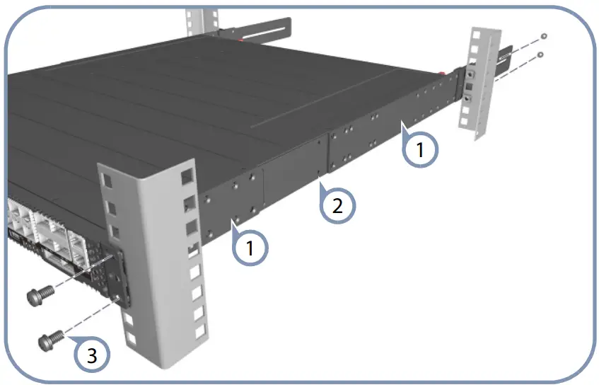
- Attach each of the front- and rear-post brackets to the switch using four of the included bracket screws.
- Use an additional two screws to secure each of the rear-post brackets at the mid-point on the sides of the switch.
- Use the screws and cage nuts supplied with the rack to secure the switch in the rack.
Adjust Rear-Post Bracket Ears
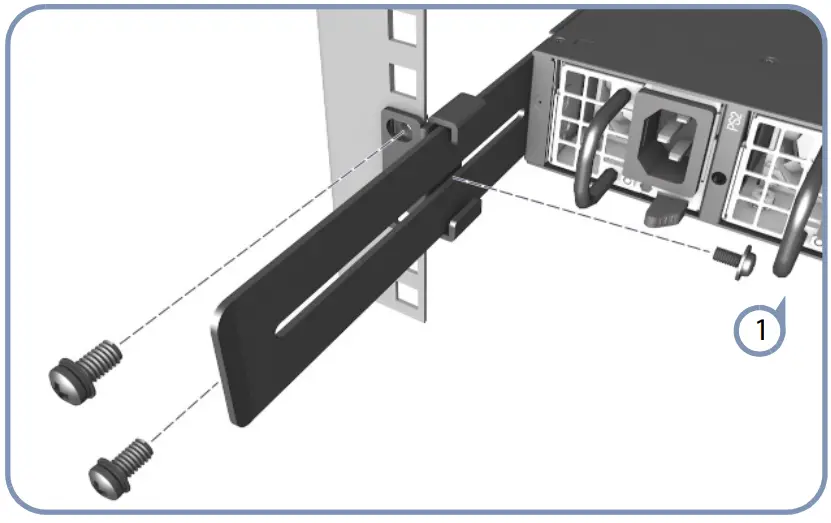
- Lock the position of the rear-post bracket ears using the included position-locking screws. You can also adjust the rear-post bracket ears to fit different rack depths from 56 cm to 75 cm.
Ground the Switch
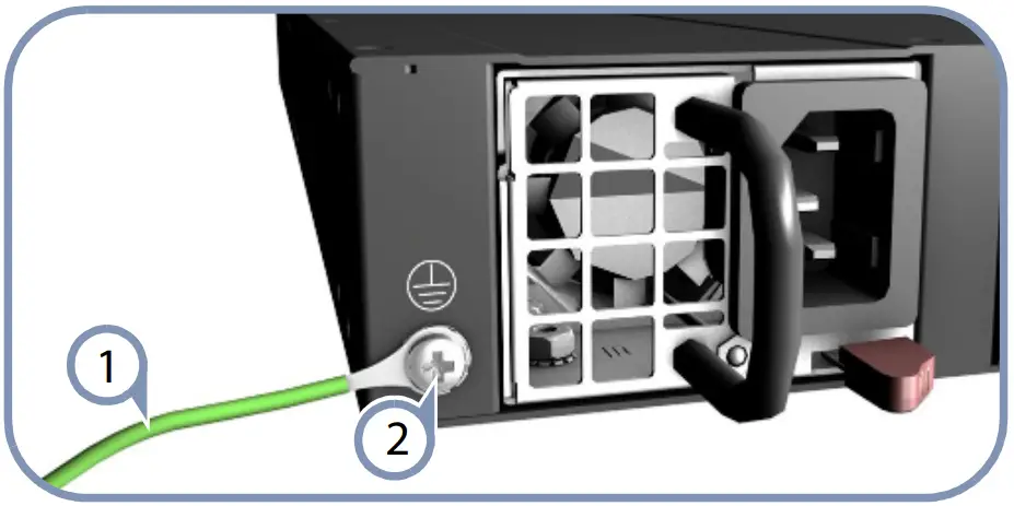
- Ensure the rack is properly grounded and in compliance with ETSI ETS 300 253. Verify that there is a good electrical connection to the grounding point on the rack (no paint or isolating surface treatment).
- Attach the grounding wire #14 AWG to the grounding point on the switch rear panel. Then connect the other end of the wire to rack ground. For details on grounding the switch with a 12 VDC PSU in an Open Rack, refer to the Edgecore ORSA-1 U Open Rack Tray Set Installation Guide.
![]() Caution: The earth connection must not be removed unless all supply connections have been disconnected.
Caution: The earth connection must not be removed unless all supply connections have been disconnected.
Connect Power
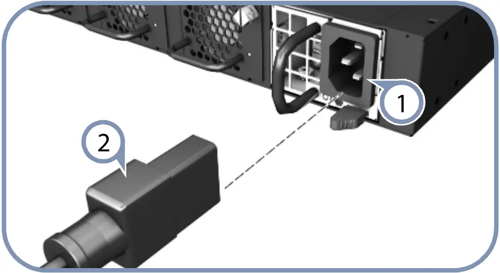
- Install one or two AC or DC power modules in the switch. The switch supports up to two PSUs that must have the same matching airflow direction as the installed fan tray.
- Connect an external AC or DC power source to the modules.

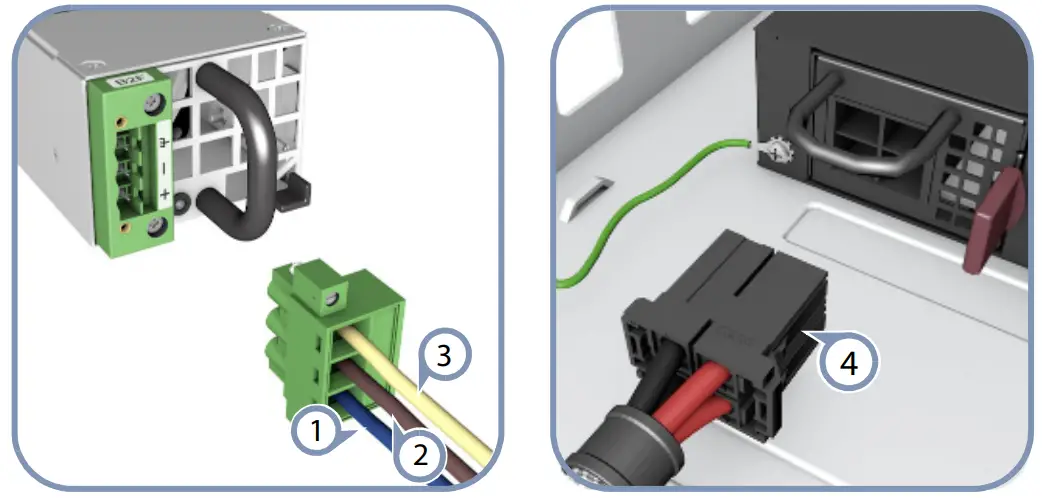
![]() Caution: Use a UL/IEC/EN 60950-1 certified power supply to connect to a DC converter, and a #14 AWG (for 36-75 VDC PSU) or #10 AWG (for 12 VDC PSU) wire to connect to a DC PSU.
Caution: Use a UL/IEC/EN 60950-1 certified power supply to connect to a DC converter, and a #14 AWG (for 36-75 VDC PSU) or #10 AWG (for 12 VDC PSU) wire to connect to a DC PSU.
Verify Switch Operation
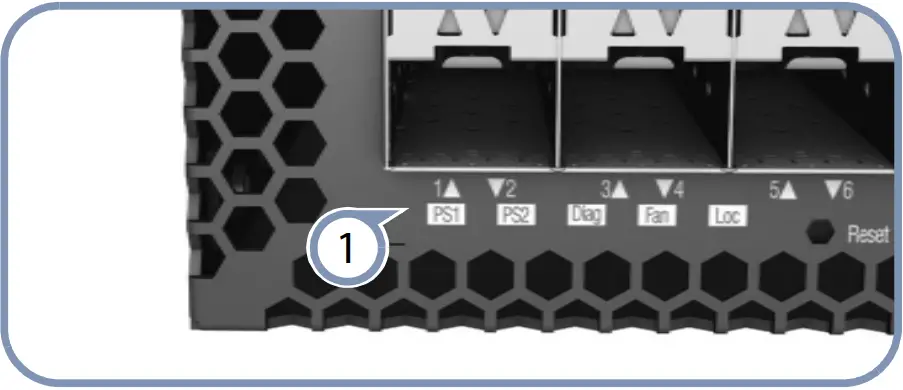
- Verify basic switch operation by checking the system LEDs. When operating normally, the PSU1/PSU2 and Fan LEDs should all be on green.
Perform Initial System Boot
- If the network operating system (NOS) installer is located on a network server, first connect the RJ-45 Management (Mgmt) port to the network using 100-ohm Category 5, 5e or better twisted-pair cable. (Not required if the NOS installer is located on attached storage.)
- Boot the switch. Wait for the ONIE software to locate and execute the NOS installer, and then wait for the installer to load the NOS software image. Subsequent switch boots will bypass ONIE and directly run the NOS software.
![]() Note: For switches with ONIE software pre-loaded, refer to the network operating system (NOS) installer and NOS documentation for details on software options and set up for ONIE.
Note: For switches with ONIE software pre-loaded, refer to the network operating system (NOS) installer and NOS documentation for details on software options and set up for ONIE.
Connect Network Cables
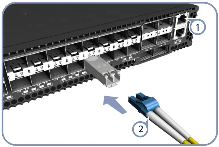
For the RJ-45 Management port, connect 100-ohm Category 5, 5e or better twisted-pair cable.
Connect DAC cables to the SFP+/QSFP+ slots. Or first install SFP+/QSFP+ transceivers and then connect fiber optic cabling to the transceiver ports. The following transceivers are supported:
Connect Network Cables
- For the RJ-45 Management port, connect 100-ohm Category 5, 5e or better twisted-pair cable.
- Connect DAC cables to the SFP+/QSFP+ slots. Or first install SFP+/QSFP+ transceivers and then connect fiber optic cabling to the transceiver ports. The following transceivers are supported:
- 40GBASE-CR4
- 40GBASE-SR4
- 10GBASE-CR
- 10GBASE-SR (ET5402-SR)
- 1000BASE-SX (ET4201-SX)
- 1000BASE-LX (ET4201-LX)
![]() Note: As connections are made, check the port status LEDs to be sure the links are valid.
Note: As connections are made, check the port status LEDs to be sure the links are valid.
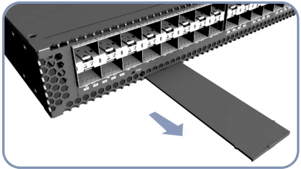
View the Product Label (For AS5712-54X/AS5812-54X only)
- The switch product label is located below SFP+ ports 7-12 on left side of the front panel. Pull the label out to view the product information.
Hardware Specifications
Switch Chassis Size (WxDxH) 438.4 x 473 x 43.4 mm (17.26 x 18.62 x 1.71 inches) Weight AS5710-54X / AS5712-54X: 8.87 kg (19.56 lb), with two installed PSUs AS5812-54X: 8.95 kg (19.73 lb), with two installed PSUs Temperature Operating: 0° C to 40° C (32° F to 104° F) Storage: -40° C to 70° C (-40° F to 158° F)
Humidity Operating: 5% to 95% (non-condensing) Power Consumption
282 Watts maximum
Regulatory Compliances
Emissions EN 55032:2012+AC:2013, Class A AS/NZS CISPR 32:2013, Class A CISPR 32:2012, Class A EN 61000-3-2:2014, Class A EN 61000-3-3:2013 FCC Class A VCCI Class A CE Mark KCC (AS5710-54X/AS5712-54X only) CCC GB 9254-2008, Class A BSMI EMI Standard CNS 13438:2006 (AS5712-54X/ AS5812 54X only) Immunity EN 55024:2010+A1:2015 EC 61000-4-2:2008 ED. 2.0 EC61000-4-3:2010 ED. 3.2 EC 61000 4-4:2012 ED. 3.0 EC 61000-4-5:2014 ED. 2.0 EC 61000 4-6:2013 ED. 4.0 EC 61000-4-8:2009 ED. 2.0 EC 61000-4-11:2004 ED. 2.0 Safety UL (CAN/CSA C22.2 No. 60950-1 & UL60950-1) CB (IEC/EN60950-1) CCC GB4943.1-2011 BSMI Safety Standard CNS14336-1
Taiwan RoHS CNS 15663