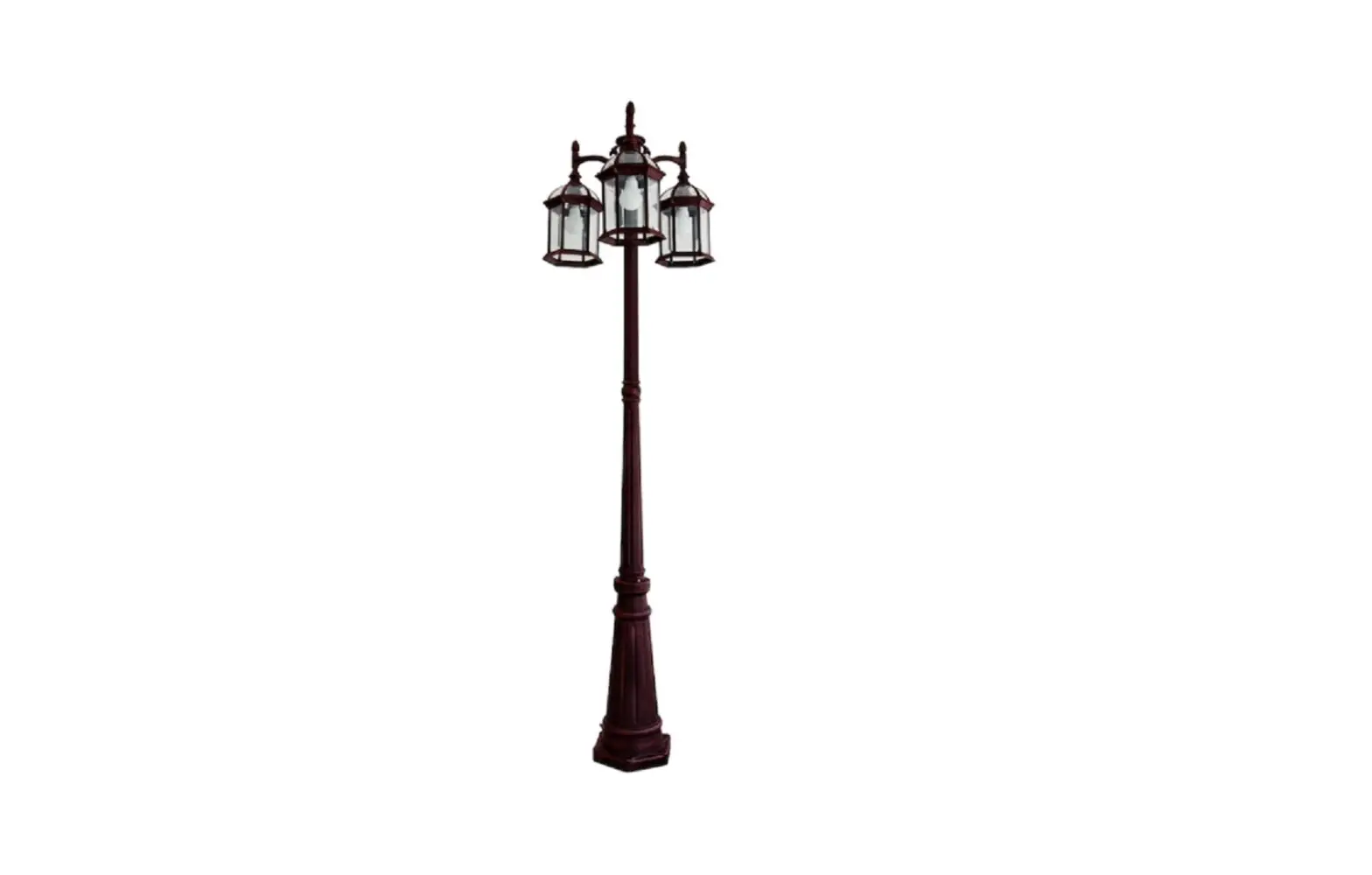
LUTEC 7150630272 Post Lantern Owner’s Manual
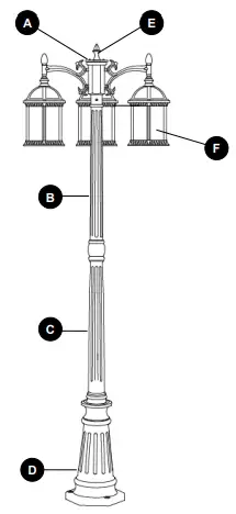
PACKAGE CONTENTS
| PART | DESCRIPTION | QUANTITY |
| A | Top Pole | 1 |
| B | Middle Pole | 1 |
| C | Bottom Pole | 1 |
| D | Base | 1 |
| E | Finial (preassembled to Top Pole (A)) | 1 |
| F | Fixture | 3 |
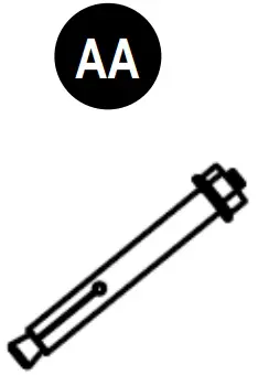
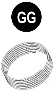
HARDWARE CONTENTS
(not shown actual size)
- Expansion Bolt
Qty. 3
- Hexagon Screw
Qty. 3
- Positioning Paper
Qty. 1
- Wrench
Qty. 1
- Wire Nut
Qty. 5
- Cap
Qty. 3
- White Wire
Qty. 1
- Black Wire
Qty. 1


SAFETY INFORMATION
Please read and understand this entire manual before attempting to assemble, operate or install the product.
![]() WARNING:
WARNING:
- Turn off electricity at main fuse box (or circuit breaker box) before beginning installation by removing fuse (or switching off circuit breaker).
- Be careful not to damage or cut the wire insulation (covering) during fixture installation. Do not permit wires to contact any surface having a sharp edge. To do so may damage or cut the wire insulation, which could cause serious injury or death from electric shock.
![]() CAUTION:
CAUTION:
- All electrical connections must be in agreement with local codes, ordinances or the National Electric Code (NEC). Contact your municipal building department to learn about your local codes, permits and/or inspections.
- Risk of fire — most dwellings built before 1985 have supply wire rated for 140ºF. Consult a qualified electrician before installation.
- Do not connect this fixture to an electrical system that does not provide a means for equipment grounding. Never use a fixture in a two-wire system that is not grounded. If you are not sure your lighting system has a grounding means, do not attempt to install this fixture. Contact a qualified, licensed electrician for information with regards to proper grounding methods as required by the local electrical code in your area.
- If a dimmer control switch is used with this fixture, obtain professional advice to determine the correct type and electrical rating required.
PREPARATION
Before beginning to assemble or install lighting fixture, make sure all parts are present. Compare parts with package contents list and hardware contents list. If any part is missing or damaged, do not attempt to assemble, install or operate the product.
Estimated Assembly Time: 30 minutes
Tools Required for Assembly (not included): Flathead Screwdriver, Phillips Screwdriver, Pliers, Electrical Tape, Wire Cutters, Safety Glasses, Ladder, Wire Stripper, 1/2 in. Wrench, 1/2 in. Ring Spanner, Electric Drill.
ASSEMBLY INSTRUCTIONS
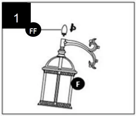
- Secure the caps (FF) to the fixtures (F).

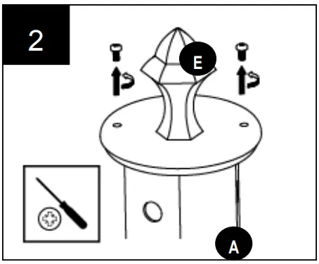
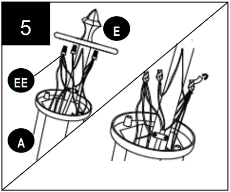
- Remove the preassembled screws with a Phillips screwdriver (not included) to detach the finial (E) from the top pole (A) and place them in a safe location.

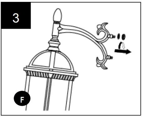
- Remove the preassembled nut and washer from each fixture (F). Save for later use.
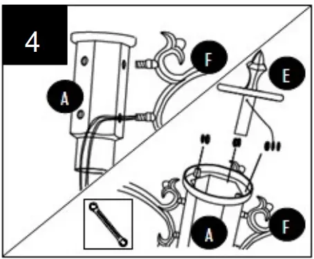
- Guide the electrical wire on the fixture (F) through the bottom hole of the top pole (A). Insert the threaded ends of the fixture (F) into the holes on the top pole (A), installing the preassembled ground wire on the bar of the finial (E) to the threaded end of the fixture (F) before securing the assembly from the inside with previously removed washers and nuts.
Tighten with a 1/2 in. ring spanner (not included).
Repeat for remaining fixtures (F). - Connect white wire from each fixture (F) to the white wire (GG) by twisting a wire nut (EE) onto bare ends of the wires. Connect the black wire from each fixture (F) to the black wire (HH) by twisting a second wire nut (EE) onto the bare ends of the wires. Secure the wire nuts (EE) with electrical tape (not included).

Hardware Used
Wire Nut x 2
White wire x 1
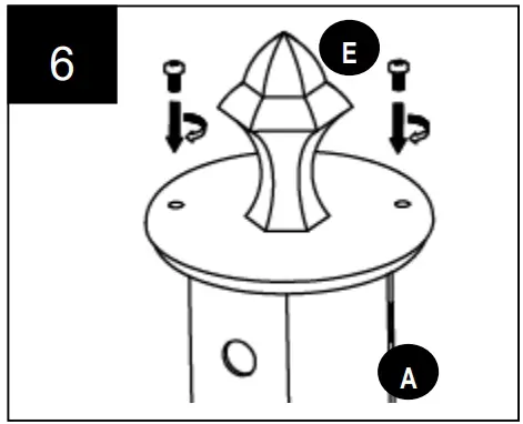
Black wire x 1 - Replace the finial (E) on the top pole (A) with the previously removed screws.

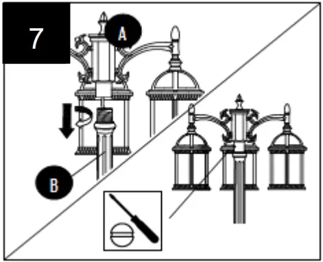
- Secure the top pole (A) to the middle pole (B), securing with the preassembled set screws. Tighten with flathead screwdriver (not included).
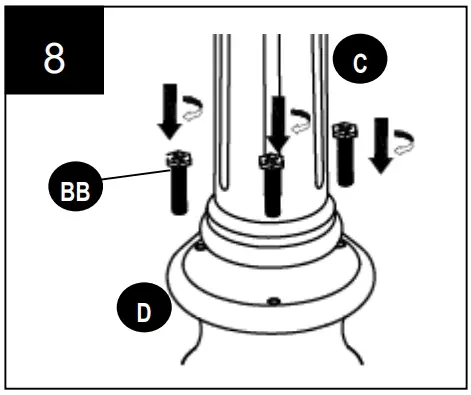
- Secure the bottom pole (C) to the base (D) with the hexagon screws (BB) by using the wrench (DD).

Hardware Used
Hexagon Screw x 3
Wrench x 1
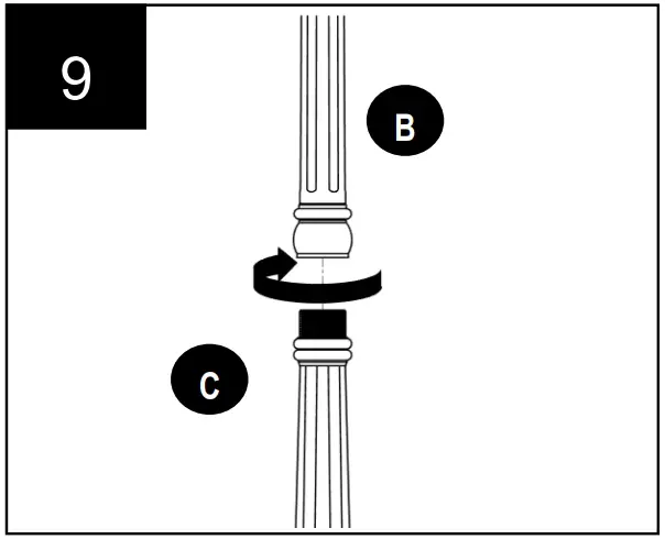
- Screw the middle pole (B) clockwise onto the bottom pole (C).

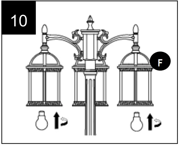
- Insert bulbs (not included). Use 100-watt max. medium-base E26 incandescent bulbs.
Note: CFLs and LEDs are recommended for this item.
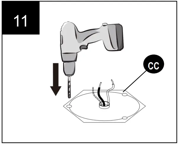
- Use the positioning paper (CC) to drill three holes on the ground.
Hardware Used
Positioning Paper x 1
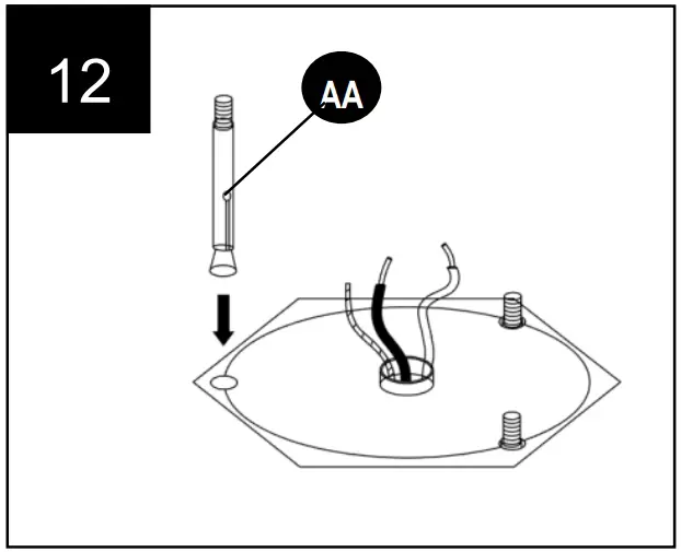
- Remove the preassembled nut and washer from the expansion bolts (AA). Then put the expansion bolts (AA) into the drill holes.

Hardware Used
Expansion Bolt x 3
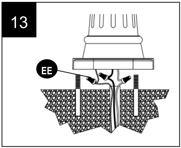
- Connect bare ground wire from the base (D) to the ground wire coming from the ground by twisting a wire nut (EE) onto bare ends of the wires. Connect white wire from the base (D) to the white wire coming from the ground by twisting a wire nut (EE) onto bare ends of the wires. Connect the black wire from the base (D) to the black wire coming from the ground by twisting a wire nut (EE) onto the bare ends of the wires. Secure the wire nuts (EE) with electrical tape.

Hardware Used
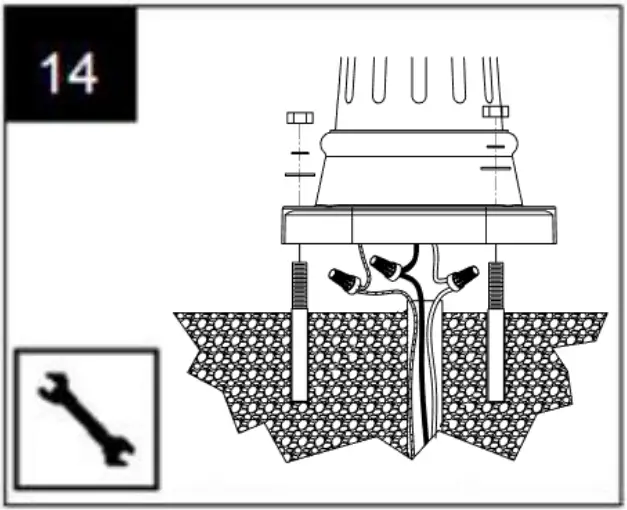
Wire Nut x 3 - With the help of another person, align the holes on base (D) with the expansion bolts and carefully place the pole assembly over the positioning paper. Secure assembly with washers and nuts removed in step 12.


CARE AND MAINTENANCE
To clean, unplug lamp and wipe with a damp, non-abrasive cloth.
TROUBLESHOOTING
| PROBLEM | POSSIBLE CAUSE | CORRECTIVE ACTION |
| The light will not go on. |
|
|
| Fuse blows or circuit trips when fixture is turned on. | Crossed wires or power wire is grounding out. | Consult a certified electrician. |
| The fixture shakes in high winds. | The screws and nuts may be secured incorrectly. | Make sure the screws and nuts were secured tightly |
3-YEAR LIMITED WARRANTY
If this product fails due to a defect in materials or workmanship within three (3) years from the date of purchase, return it along with proof of date of purchase and it will be replaced with the same or comparable model free of charge.
This warranty is void if damage or defect has resulted from accident, abuse, misuse or faulty repair.
This warranty gives you specific legal rights and you may have other rights that vary from state to state.
IN NO EVENT WILL LIABILITY EXTEND TO ANY CONSEQUENTIAL, SPECIAL, INCIDENTAL OR INDIRECT DAMAGES OF ANY KIND ARISING OUT OF THE USE OR MISUSE OF THIS PRODUCT. SOME STATES DO NOT ALLOW THE EXCLUSION OR LIMITATION OF INCIDENTAL OR CONSEQUENTIAL DAMAGES SO THE ABOVE EXCLUSION OR LIMITATION MAY NOT APPLY TO YOU.
Customer Support
UTEC USA LLC:
149B Houston Rd Troutman NC 28166
Ningbo UTEC Electric Co.,LTD
CN8, Far East Industry Park, Yuyao, China
Web: www.lutec.com
Email: [email protected]
Please call our Customer Service line at 877-714-8669 for assistance Monday – Friday 9 a.m. to 5 p.m. EST


