Buyers Electric Tongue Jack 0093500 Installation Guide
APPLICATION
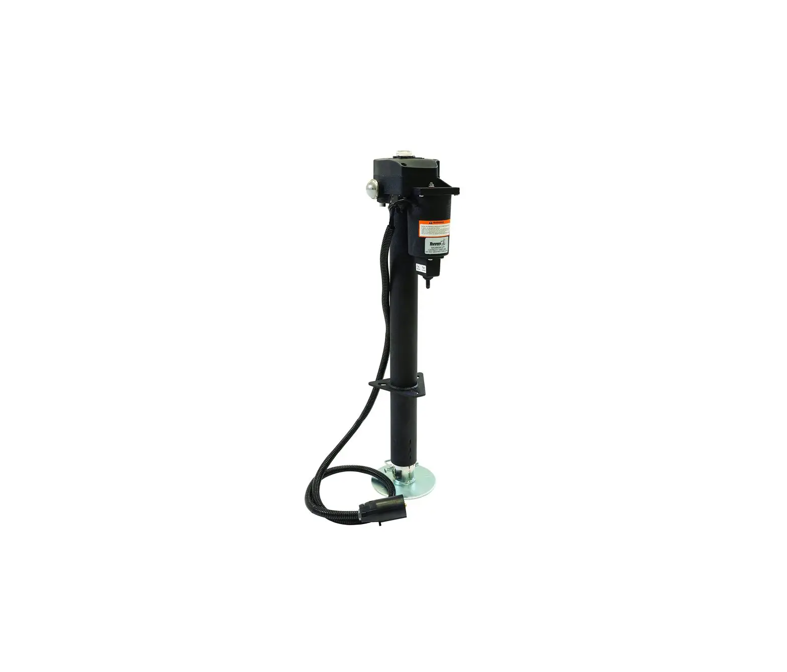
The Electric Tongue Jack is a 12-volt motor-driven screw jack for use on travel trailers and boat trailers.
SPECIFICATIONS
Vertical Load – 3500 lbs. continuous over full stroke with 5000 lbs. instantaneous tongue breakaway capacity. Travel-18″
Power Requirement -12 volt D.C.
Retracted Height – 26-1/2″
Removable Foot Pad – 5-1/4″ Dia.
Approximate Shipping Weight – 22 lbs.
NOTE
Many OEM truck trailer connectors do not have the AUXILIARY POWER/BATTERY CHARGE terminal connected from the factory.
If the jack does not work when connected, it may be necessary to contact your truck dealer for instructions on enabling the circuit or checking the appropriate fuse or breaker.
If your jack fails to function, use a test light between the terminals shown below to determine if you have power at the appropriate terminals.
INSTALLATION
- Block the wheels and support the trailer “A” frame securely.
- Remove the existing jack.
NOTE: Save the original nuts, bolts, and washers for installing the Electric Tongue Jack. - Install the Electric Tongue Jack using original nuts and bolts.
- The Electric Tongue Jack was designed to replace an existing crank down jack. The diameter of the outer tube of your chosen jack, will need to match the existing hole size, or you will need to modify the hole diameter to fit.
- Align the motor head so that the motor housing is facing the front of the “A” frame.
- Connect 7-pin trailer connector to vehicle’s trailer plug, or, if hard wiring connect the black positive lead to the positive terminal of the battery. The Electric Tongue Jack is internally grounded, and needs no ground wire if “A” frame is properly grounded.
![]() WARNING
WARNING
When using an extension wire, DO NOT use smaller than #10 gauge wire.
OPERATION
- Block trailer wheels securely.
- The Electric Tongue Jack is operated by means of the Toggle Switch located under the motor housing.
- Extend the jack by holding the Toggle Switch in the Extend position.
 CAUTION
Release the Toggle Switch when the motor switches off to prevent damage to motor and #14 Headed Pin. Wait 15 seconds for the motor to reset before operating the jack again. - Retract the jack by holding the Toggle Switch in the Retract position. As the jack approaches the fully retracted position it will slow down and then stall. The Toggle Switch should be released at the first indication of slowing down. The jack is now fully retracted.
NOTE: If the motor should stall with the jack in the fully retracted position, and the Toggle Switch Is not released, the motor will automatically switch off.
MANUAL OPERATION
- Remove level gauge in the access hole, (located top center of the housing cover)
- Insert the crank handle in the access hole, over the drive spindle tang. Rotate the crank handle clockwise to retract and counter clockwise extend.
- When complete, remove crank handle and replace level gauge and reassemble the fuse connection.
LUBRICATION
The jack is lubricated before leaving the factory. Under normal conditions, lubrication will be needed after one year.
![]() WARNING
WARNING
The weight of the Trailer tongue should be supported by blocks or the Ball Hitch of the tow vehicle before proceeding.
- The Foot should be fully extended.
- Using the Toggle Switch, extend the jack until the Foot Pad is 2″ from the ground.
- Loosen the four #8 Phillips Head Screws and remove the Gear Housing Cover.
- If required, repack the exposed gears with a common Lithium Base Machine Grease.
- Reassemble Gear Housing Cover.
- Using a 1/4″ Allen Wrench, remove the four 5/16″ Socket Head Screws holding the Motor Head to the Outer Tube.
- Lift the Motor Head and Screw Assembly away from the Outer Tube.
- Clean and regrease the Jack Screw and Nut with a common Lithium Base Machine Grease.
- Reassemble Motor Head and Screw Assembly to Outer Tube. Replace the Fuse.
Motor Exploded View
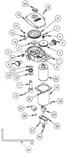
Bill of Materials
| ITEM PART NO. | QTY. | DESCRIPTION |
| 1 | 1 | Main Housing |
| 2 | 1 | Thrust Washer |
| 3 | 1 | Bushing |
| 4 | 1 | Bushing |
| 5 | 1 | Spur Gear |
| 6 | 1 | Pin |
| 7 | 1 | Pinion Gear |
| 8 | 1 | Main Gear |
| 9 | 2 | Light |
| 10 | 1 | Housing Cover |
| 11 | 1 | Collar |
| 12 | 2 | Hard. Washer |
| 13 | 1 | Thrust Bearing |
| 14 | 1 | Headed Pin |
| 15 | 1 | Pin |
| 16 | 1 | 1/4 Lock Washer |
| 17 | 1 | 1/4 Cap Bolt |
| 18 | 8 | #8-32 Screw |
| 19 | 1 | Motor Housing |
| 20 | 1 | Switch Housing |
| 21 | 4 | #5-40 Screw |
| 22 | 1 | Motor |
| 23 | 1 | Motor Switch |
| 24 | 1 | Level Gauge |
| 25 | 1 | Grommet |
| 26 | 1 | Boot Snap Seal |
| 27 | 1 | Circuit Breaker |
| 28 | 2 | #8 Screw |
| 29 | 1 | Light Switch |
| Note: Not Shown | ||
| TC2007P | 1 | 7-Pin RV Trailer Connector |
Replacement Parts
| ITEM | PART NO. | QTY. | DESCRIPTION | |
| 9 | 3013226 | 1 | Light Cover, Plastic | |
| 14 | 3013231 | 1 | Headed Pin | |
| 22 | 3013239 | 1 | Motor | |
| 24 | 3013240 | 1 | Level Gauge | |
| 29 | 3013246 | 1 | Light Switch | |
| 30 | 3013247 | 1 | Manual Crank | |
| 10 | 3013227 | 1 | Housing Cover | |
| 19,25 | 3013319 | 1 | Motor Housing | |
| 20,23, | 26 | 3013320 | 1 | Switch Assembly |
| – | 3018025 | 1 | 30 Amp “Slow Blow” Fuse (older models) | |
| 3018026 | 1 | LED Light | ||
| 3018027 | 1 | Light Socket |
Lower Stem Assembly Exploded View
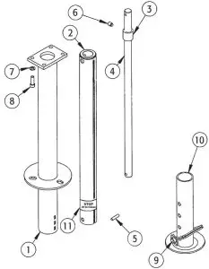
Bill of Materials
| ITEM PART NO. | QTY. | DESCRIPTION |
| 1 | 1 | 2.25″ Outer Tube |
| 2 | 1 | 2″ Inner Tube |
| 3 | 1 | Bronze Nut |
| 4 | 1 | Jackscrew |
| 5 | 1 | Pin |
| 6 | 1 | 3/8 Set Screw |
| 7 | 4 | 5/16 Lock Washer |
| 8 | 4 | 5/16 Cap Screw |
| 9 | 1 | 3/8 Snapper Pin |
| 10 | 1 | Footpad |
| 11 | 1 | Label, STOP, Do Not Retract… |
Replacement Parts
| ITEM | PART NO. | QTY. | DESCRIPTION |
| 9 | 3013260 | 1 | 3/8 Snapper Pin |
| 10 | 3013261 | 1 | Footpad |
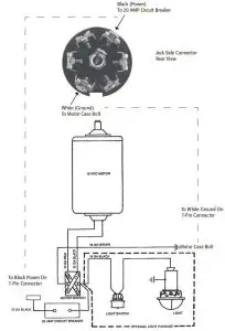
Wiring Diagram
Shop for quality Buyers products on our website.
On Our website you Can discover more about trailer hitches and towing.


