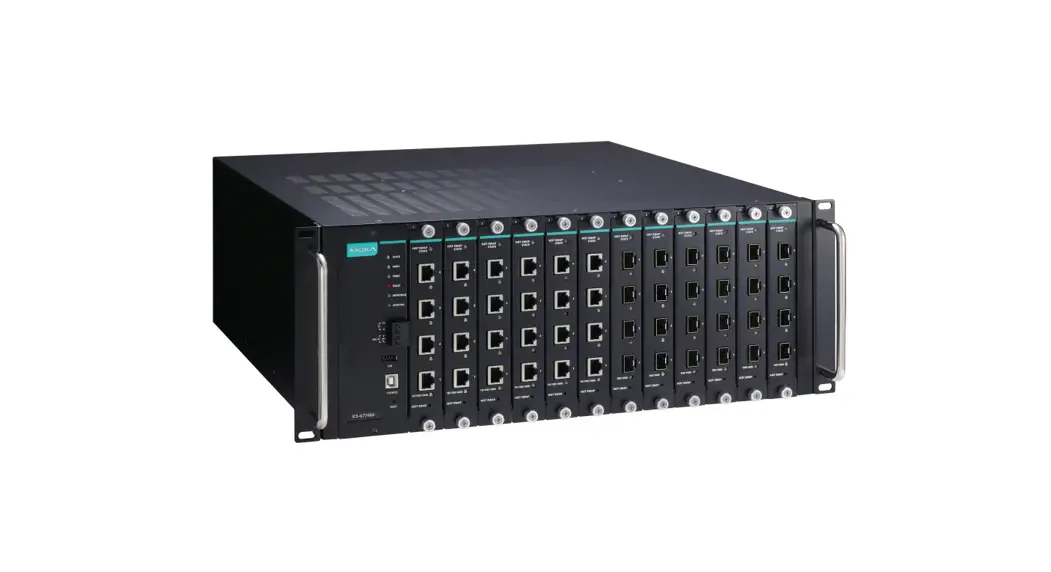
![]() ICS-G7748A/G7750A/G7752A/G7848A/G7850A/G7852A Series
ICS-G7748A/G7750A/G7752A/G7848A/G7850A/G7852A Series
Industrial Rackmount Switch
Installation Guide
Package Checklist
- ICS-G7748A or ICS-G7750A or ICS-G7752A or ICS-G7848A or ICSG7850A or ICS-G7852A switch
- USB cable (Type A male to Type B male)
- Power cord
- 2 PWR-G7000A-AC power modules are preinstalled
- 4 protective caps for unused ports and 2 for USB type A and type B
- 2 rackmount ears and metal handles
- 12 cover plates are preinstalled
- Quick installation guide (printed)
- Warranty card
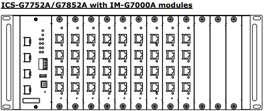
Panel Layouts
Front View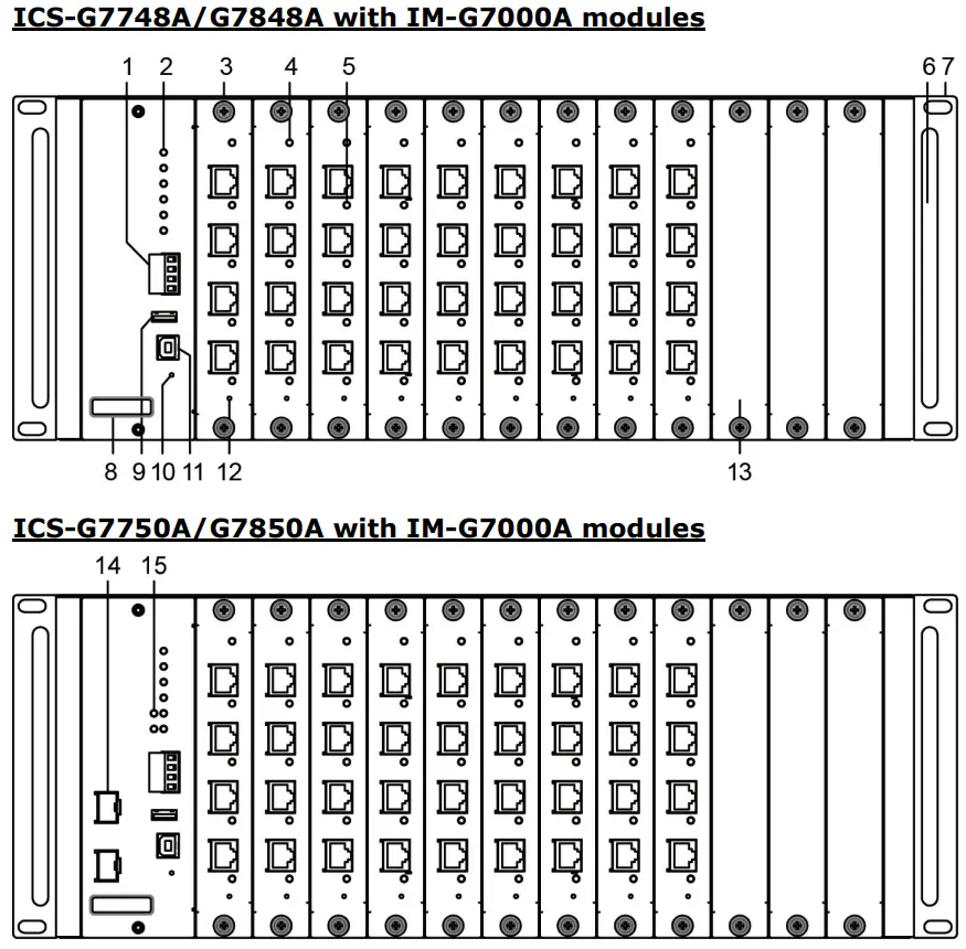
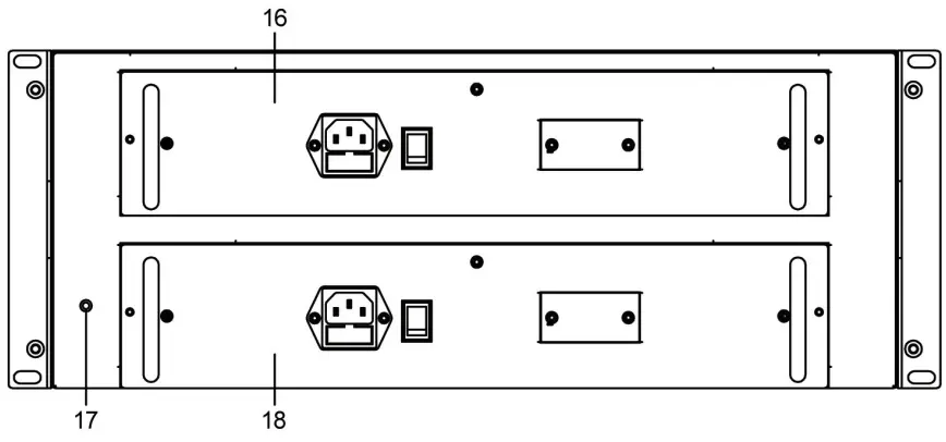
 Rear View
Front View of IM-G7000A Modules
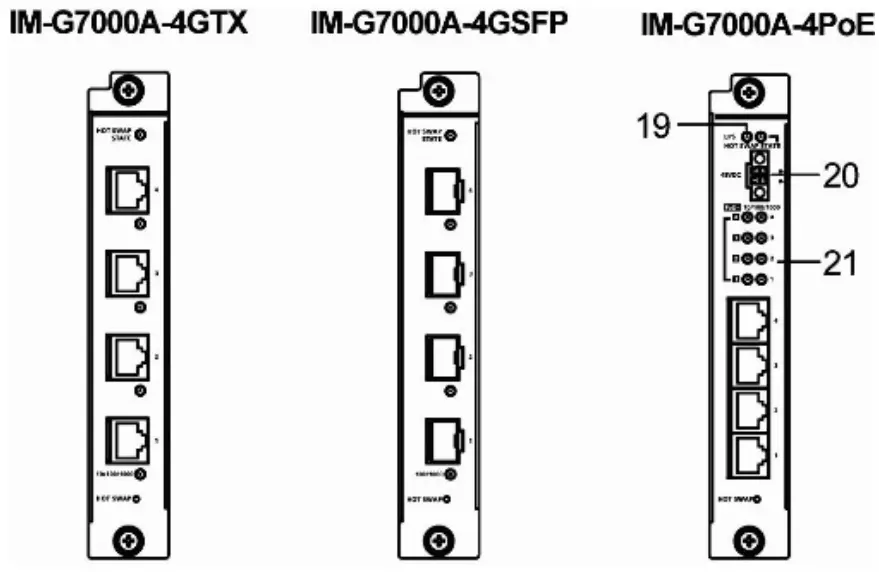
- Terminal block for Relay Output and Digital Input
- System status LEDs
- Copper module slot for 10/100/1000BaseT(X) port or SFP module slot for 100/1000BaseSFP
- Hot-swap status LED
- 10/100/1000BaseT(X) port status LEDs or 100/1000BaseSFP port status LEDs
- Metal handle
- 19” rack-mount ear
- Model name
- USB storage port (ABC-02-USB)
- Reset button
- USB serial console port
- Hot-swap button
- Metal cover plate
- 10 Gigabit Ethernet SFP+ slot
- 10 Gigabit Ethernet SFP+ port status LEDs
- First PWR-G7000A-AC power module (PWR1)
- Grounding screw
- Second PWR-G7000A-AC power module (PWR2)
- External power supply for the PoE status LED
- External power supply for the PoE module
- IM-G7000A-8PoE port LEDs
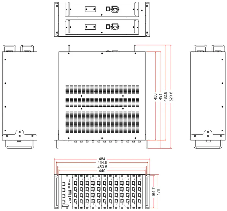
Dimensions (unit = mm)
Grounding the Industrial Rackmount Switch
Grounding and wire routing help limit the effects of noise from electromagnetic interference (EMI). Run the ground connection from the ground screw to the grounding surface prior to connecting devices.
Connecting the Power Inputs
The ICS supports dual redundant power supplies: Power Supply 1 (PWR1) and Power Supply 2 (PWR2). The connections for PWR1 and PWR2 are located on the rear of the product. Be sure to use a standard power cord with an IEC C13 connector, which is compatible with the AC power inlet.
Installing/Removing ICS Switch Modules
IM-G7000A Series modules are designed for installation in ICS switches. Before inserting the module into the slot, first remove the metal cover plate. Push the module along the track and firmly connect the module with the connector. Finally, secure the module by firmly tightening the screws.
IM-G7000A Series modules are hot-swappable. Take the following steps to remove modules from the switch:
- Push the HOT SWAP button on the module.
- Wait for the HOT SWAP STATE LED to turn off.
- Loosen the screw(s) and remove the module.
Wiring the Relay Contact
Each ICS switch has one relay output.
FAULT: The relay contact of the 4-pin terminal block connector is used to detect user-configured events. The two wires attached to the fault contacts form an open circuit when a user-configured event is triggered. If a user-configured event does not occur, the fault circuit remains closed.
USB Console Connection
The ICS has one USB console port (type B connector) located on the top panel. Use the USB cable (provided in the product package) to connect the ICS’s console port to your PC’s USB port, and install the USB driver (available on the software CD) on the PC. You may then use a console terminal program, such as Moxa PComm Terminal Emulator, to access the ICS’s console configuration utility.
USB Console Port (Type B Connector) Pinouts
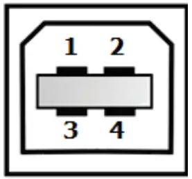
| Pin | Description |
| 1 | D– (Data -) |
| 2 | VCC (+5V) |
| 3 | D+ (Data+) |
| 4 | GND (Ground) |
USB Storage Connection
The ICS has one USB storage port (type A connector) on the front panel. Use Moxa’s ABC-02-USB automatic backup configurator to connect the ICS’s USB storage port for configuration backup, firmware upgrade, or system log file backup.
USB Storage Port (Type A Connector) Pinouts

| Pin | Description |
| 1 | VCC (+5V) |
| 2 | D– (Data -) |
| 3 | D+ (Data+) |
| 4 | GND (Ground) |
NOTE DO NOT remove the ABC-02-USB USB Automatic Backup Configurator while writing or reading data.
Depress the Reset button continuously for five seconds to load the factory default settings. Use a pointed object, such as a straightened paper clip or toothpick, to depress the Reset button. When you do so, the STATE LED will start to blink about once per second. Continue to depress the STATE LED until it begins blinking more rapidly, which indicates that the button has been depressed for five seconds and you can release the Reset button to load factory default settings.
NOTE DO NOT power off the switch when loading default settings.
LEDs
| LED | Color | State | Description |
| System LEDs | |||
| STATE | GREEN | On | System has passed the self-diagnosis test on boot-up and is ready to run. |
| Blinking | 1. System is undergoing the self- diagnosis test 2. Blink continuously when pressing the reset button 5 seconds to reset to factory default 3. Blink slowly when an ABC-02 automatic backup device is detected | ||
| RED | On | System failed self-diagnosis on boot-up. | |
| PWR1 | AMBER | On | Power is being supplied to the main module’s power input PWR1. |
| Off | Power is not being supplied to the main module’s power input PWR1. | ||
| PWR2 | AMBER | On | Power is being supplied to the main module’s power input PWR2. |
| Off | Power is not being supplied to the main module’s power input PWR2. | ||
| FAULT | RED | On | System is in the event of failure, or is under quick inspection. |
| Off | System is in normal operation. | ||
| MSTR/ HEAD | GREEN | On | The switch is set as the Master of the Turbo Ring, or as the Head of the Turbo Chain. |
| Blinking | Switch has become the Ring Master of the Turbo Ring, or the Head of the Turbo Chain, after the Turbo Ring or the Turbo Chain is down. | ||
| Off | The switch is not the Master of this Turbo Ring or is set as a Member of the Turbo Chain | ||
| CPLR/ TAIL | GREEN | On | Switch’s coupling function is enabled to form a back-up path, or when it’s set as the Tail of the Turbo Chain. |
| Blinking | Turbo Chain is down | ||
| Off | Switch has disabled the coupling function. | ||
When the system is importing/exporting data from or to an ABC-02 automatic backup device, the FAULT, MSTR/HEAD, and CPLR/TAIL LEDs will blink in sequence.
| LED | Color | State | Description |
| Main Module LED Status | |||
| 10 GbE (Fiber Optic Port) | GREEN | On | The corresponding port’s link is active. |
| Blinking | Data is being transmitted. | ||
| Off | The corresponding port’s link is inactive. | ||
| IM-G7000A- 4GTX 10/100/1000 Mbps (TP Ports) | GREEN | On | The corresponding port’s link is active at 1000 Mbps. |
| Blinking | Data is being transmitted at 1000 Mbps. | ||
| Off | The corresponding port’s link is inactive. | ||
| AMBER | On | The corresponding port’s link is active at 10/100 Mbps | |
| Blinking | Data is being transmitted. | ||
| Off | The corresponding port’s link is inactive. | ||
| IM-G7000A- 4GSFP 100/1000 Mbps (Fiber Optic Ports) | GREEN | On | The corresponding port’s link is active at 1000 Mbps |
| Blinking | Data is being transmitted. | ||
| Off | The corresponding port’s link is inactive. | ||
| AMBER | On | The corresponding port’s link is active at 100 Mbps | |
| Blinking | Data is being transmitted. | ||
| Off | The corresponding port’s link is inactive. | ||
| IM-G7000A- 4PoE (PoE+Ports) | GREEN | On | The PoE device is connected by the IEEE 802.3at standard. |
| Off | No PoE power is being output or no PoE devices are connected. | ||
| AMBER | On | The PoE device is connected by the IEEE 802.3af standard | |
| Off | No PoE power is being output or no PoE devices are connected. | ||
| RED | Blinking | PoE failure: • 1 time/s: PoE standard detection failure • 2 times/s: PoE current overload | |
| Off | No PoE failure | ||
| EPS (IM- G7000A- 4PoE module only) | Amber | On | External power supply is working for PoE+ power output |
| Off | External power supply is not working for PoE+ power output | ||
| HOT SWAP STATE | GREEN | On | The module is working |
| Blinking | The module is uninstalling | ||
| Off | The module is not working or can be safely removed. | ||
Specifications
| Technology | |
| Standards | IEEE 802.3 for 10BaseT IEEE 802.3u for 100BaseT(X) and 100BaseFX IEEE 802.3ab for 1000BaseT(X) IEEE 802.3z for 1000BaseSX/LX/LHX/ZX IEEE 802.3ae for 10 Gigabit Ethernet IEEE 802.3x for Flow Control IEEE 802.1D-2004 for Spanning Tree Protocol IEEE 802.1w for Rapid Spanning Tree Protocol IEEE 802.1s for Multiple Spanning Tree Protocol IEEE 802.1Q for VLAN Tagging IEEE 802.1p for Class of Service IEEE 802.1X for Authentication IEEE 802.3ad for Port Trunk with LACP |
| Protocols | IGMPv1/v2, GMRP, GVRP, SNMPv1/v2c/v3, DHCP Server/Client, BootP, TFTP, SNTP, SMTP, RARP, RMON, HTTP, HTTPS, Telnet, Syslog, DHCP Option 66/67/82, SSH, LLDP, IEEE 1588 PTP V2, EtherNet/IP, Modbus/TCP, SNMP Inform, NTP Server/Client, IPv6 (ICS-G7700A series) |
| Layer 3 Switching (ICS-G7800A) | Static routing, RIP V1/V2, OSPF, DVMRP, PIM- DM, PIM-SM, PIM-SSM |
| Layer 3 Switching Redundancy (ICS-G7800A) | VRRP |
| MIB | MIB-II, Ethernet-like MIB, P-BRIDGE MIB, Q- BRIDGE MIB, Bridge MIB, RSTP MIB, RMON MIB Groups 1, 2, 3, 9 |
| Flow Control | IEEE 802.3x flow control, back pressure flow control |
| Interface | |
| Gigabit Ethernet | 10/100/1000BaseT(X) or 100/1000BaseSFP slot |
| 10 Gigabit Ethernet | 10GbE SFP+ slot |
| Console Port | USB-serial console (Type B connector) |
| Storage Port | USB storage (Type A connector for ABC-02-USB) |
| LED Indicators | STATE, PWR1, PWR2, FAULT, MSTR/HEAD, CPLR/TAIL |
| Alarm Contact | 1 relay output with current carrying capacity of 2 A @ 30 VDC |
| Digital Inputs | 1 input with the same ground, but electrically isolated from the electronics. • +13 to +30 V for state “1” • -30 to +1 V for state “0” • Max. input current: 8 mA |
| Power Requirements | |
| Input Voltage | ICS-G7000A Switch: 110/220 VAC (85 to 264 VAC) IM-G7000A-4PoE Module: 48 VDC (46 to 57 VDC) |
| Input Current | ICS-G7748A/7848A Series: Max. 0.98/0.61 A @ 110/220 VAC ICS-G7750A/7850A Series: Max. 1.1/0.72 A @ 110/220 VAC ICS-G7752A/7852A Series: Max. 1.31/0.83 A @ 110/220 VAC Note: These are the input current ratings for the device with the maximum number of modules installed. |
| Power Consumption (Max.) | ICS-G7748A/7848A Series: Max. 99/97.26 W @ 110/220 VAC ICS-G7750A/7850A Series: Max. 109.68/117.8 W @ 110/220 VAC ICS-G7752A/7852A Series: Max. 120.38/138.34 W @ 110/220 VAC Note: These are the power consumption ratings for the device with the maximum number of modules installed. |
| Total PoE Power Budget | With IM-G7000A-4PoE Module: Max. 1,440 W @ 48 VDC |
| Overload Current Protection | Present |
| Physical Characteristics | |
| Housing | IP30 protection |
| Dimensions | 440 x 176 x 482.8 mm (17.32 x 6.93 x 20.62 in) |
| Weight | 12.9 kg |
| Installation | 4U 19” rack mounting |
| Environmental Limits | |
| Operating Temp. | -10 to 60°C (14 to 140°F) |
| Storage Temp. | -40 to 85°C (-40 to 185°F) |
| Ambient Relative Humidity. | 5 to 95% (non-condensing) |
| Standards and Certifications | |
| Safety | UL 60950-1, EN 60950-1 |
| EMI | FCC Part 15 Subpart B Class A, EN 55032 Class A |
| EMS | EN 61000-4-2 (ESD) Level 3 EN 61000-4-3 (RS) Level 3 EN 61000-4-4 (EFT) Level 3 EN 61000-4-5 (Surge) Level 3 EN 61000-4-6 (CS) Level 3 EN 61000-4-8 EN 61000-4-11 |
| Rail Traffic | EN 50121-4 |
| Shock | IEC 60068-2-27 |
| Freefall | IEC 60068-2-32 |
| Vibration | IEC 60068-2-6 |
| Warranty | |
| Warranty Period | 5 years |
| Details | See www.moxa.com/warranty |
Rack Mounting Instructions
- Elevated Operating Ambient: If installed in a closed or multi-unit rack assembly, the operating ambient temperature of the rack environment may be greater than room ambient. Therefore, consideration should be given to installing the equipment in an environment compatible with the maximum ambient temperature (Tma) specified by the manufacturer.
- Reduced Air Flow: Installation of the equipment in a rack should be such that the amount of air flow required for safe operation of the equipment is not compromised.
- Mechanical Loading: Mounting of the equipment in the rack should be such that a hazardous condition is not achieved due to uneven mechanical loading.
- Circuit Overloading: Consideration should be given to the connection of the equipment to the supply circuit and the effect that overloading of the circuits might have on overcurrent protection and supply wiring. Appropriate consideration of equipment nameplate ratings should be used when addressing this concern.
- Reliable Earthing: Reliable earthing of rack-mounted equipment should be maintained. Particular attention should be given to supply connections other than direct connections to the branch circuit (e.g., use of power strips).
Restricted Access Locations
- This equipment is intended to be used in Restricted Access Locations, such as a computer room, with access limited to SERVICE PERSONNEL or USERS who have been instructed on how to handle the metal chassis of equipment that is so hot that special protection may be needed before touching it. The location should only be accessible with a key or through a security identity system.
- External metal parts of this equipment are extremely hot!! Before touching the equipment, you must take special precautions to protect your hands and body from serious injury.
![]() © 2023 Moxa Inc. All rights reserved.
© 2023 Moxa Inc. All rights reserved.
Version 3.4, June 2023
Technical Support Contact Information
www.moxa.com/support![]() P/N: 1802077001015
P/N: 1802077001015


