MOXA EDS-P206A-4PoE Switch
Technical Support Contact Information www.moxa.com/support
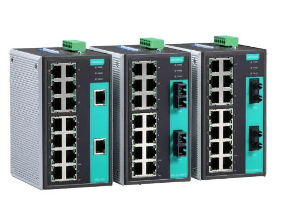
Overview
The EDS-P206A-4PoE series industrial Ethernet switches are entry-level industrial 6-port PoE Ethernet switches that support IEEE 802.3, IEEE 802.3u, and IEEE 802.3x, with 10/100M, full/half-duplex, MDI/MDIX auto-sensing, IEEE 802.3af, and IEEE 802.3at.
The EDS-P206A-4PoE series provides 12/24/48 VDC redundant power inputs that can be connected simultaneously to a live DC power source. The switches are available with a standard operating temperature range from -10 to 60°C, or with a wide operating temperature range from -40 to 75°C, and their IP30 metal housing makes them rugged enough for any harsh industrial environment.
To provide greater versatility for use with applications from different industries, the EDS-P206A-4PoE switches also allow users to enable or disable broadcast storm protection with DIP switches on the outer panel.
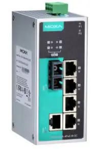
The EDS-P206A-4PoE switches can be easily installed on a DIN-Rail or in distribution boxes. The DIN-Rail mounting capability and IP30 metal housing with LED indicators make the plug-and-play EDS-P206A-4PoE switches reliable and easy to use.
NOTE Throughout this Hardware Installation Guide, we use EDS as an abbreviation for Moxa EtherDevice Switch:
EDS = Moxa EtherDevice Switch
Package Checklist
Your EDS is shipped with the following items. If any of these items are missing or damaged, please contact your customer service representative for assistance.
- Moxa EtherDevice™ Switch
- Quick installation guide (printed)
- Warranty card
Features
High-wattage Power-over-Ethernet
- Up to 30 watts per PoE port
- Active circuit protection
- Auto disconnection for over-voltage or under-voltage
- Power consumption detection and classification
High Performance Network Switching Technology
- 10/100BaseT(X) (RJ45 connector), 100BaseFX (SC/ST connector, multi/single-mode)
- 10/100M, Full/Half-Duplex, MDI/MDIX auto-sensing
- IEEE 802.3/802.3u/802.3x
- Store and Forward switching process type, 2K address entries
Rugged Design
- Redundant dual 12/24/48 VDC power input
- Operating temperature range from -10 to 60°C, or extended operating temperature of -40 to 75°C for “T” models.
- IP30 metal housing
- DIN-Rail or panel mounting capability
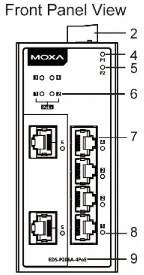
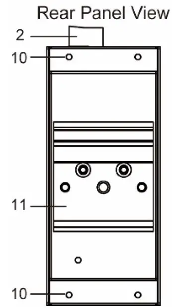
EDS-P206A-4PoE (Standard) Panel Layouts
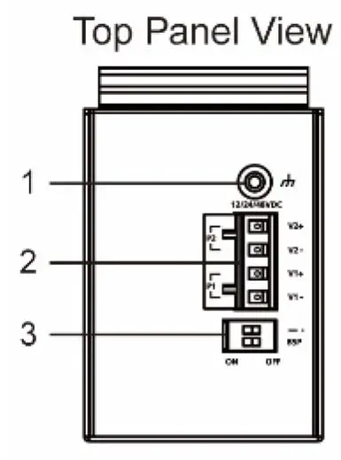
1. Grounding screw
2. Terminal block for power input P1/P2
3. DIP switches
4. Power input P1 LED
5. Power input P2 LED
6. PoE LED
7. 10/100BaseT(X) port
8. TP port’s 10/100 Mbps LED
9. Model name
10. Screw hole for wall mounting kit
11. DIN-Rail kit
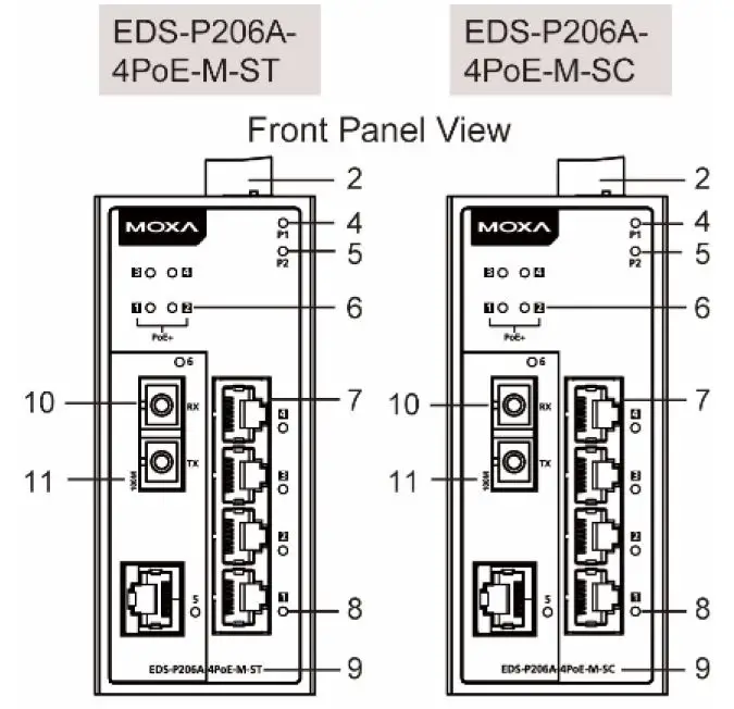
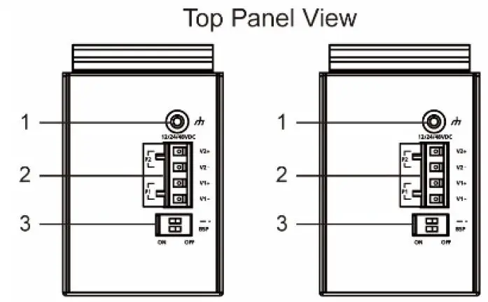
EDS-P206A-4PoE-M-SC/ST Panel Layouts
NOTE: The EDS-P206A-4PoE-S-SC/ST are identical in appearance to the EDS-P206A-4PoE-M-SC/ST.
1. Grounding screw
2. Terminal block for power input P1/P2
3. DIP switches
4. Power input P1 LED
5. Power input P2 LED
6. PoE LED
7. 10/100BaseT(X) port
8. TP port’s 10/100 Mbps LED
9. Model name
10. 100BaseFX port
11. FX port’s 100 Mbps LED
12. Screw hole for wall mounting kit
13. DIN-Rail kit
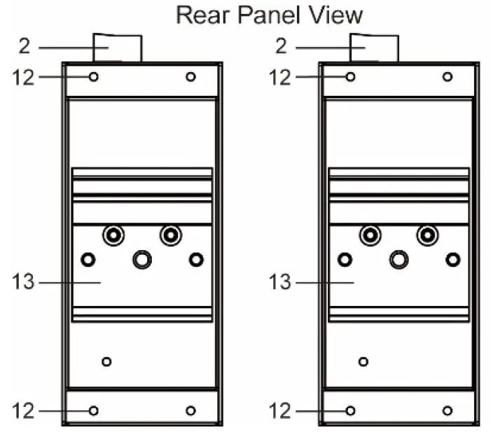
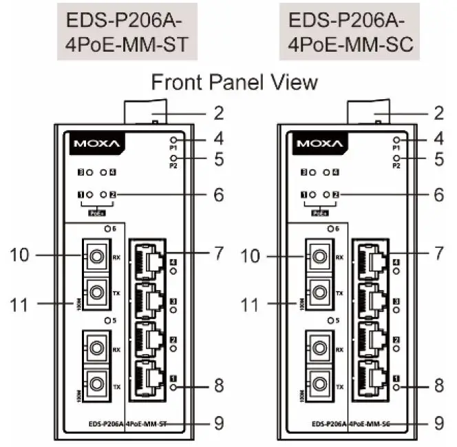
EDS-P206A-4PoE-MM-SC/ST Panel Layouts
NOTE: The EDS-P206A 4PoE-SS-SC/ST are identical in appearance to the EDS-P206A-4PoE- MM-SC/ST.
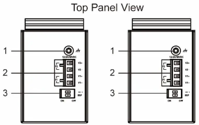
1. Grounding screw
2. Terminal block for power input P1/P2
3. DIP Switches
4. Power input P1 LED
5. Power input P2 LED
6. PoE LED
7. 10/100BaseT(X) port
8. TP port’s 10/100 Mbps LED
9. Model name
10. 100BaseFX port
11. FX port’s 100 Mbps LED
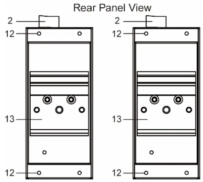
12. Screw hole for wall mounting kit
13. DIN-Rail kit
Mounting Dimensions
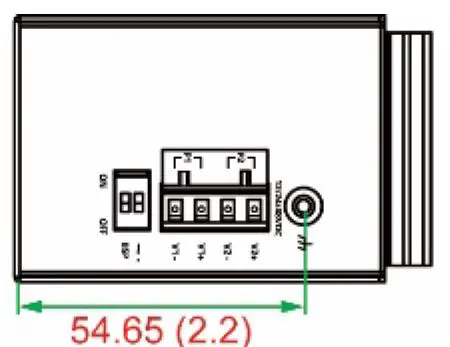
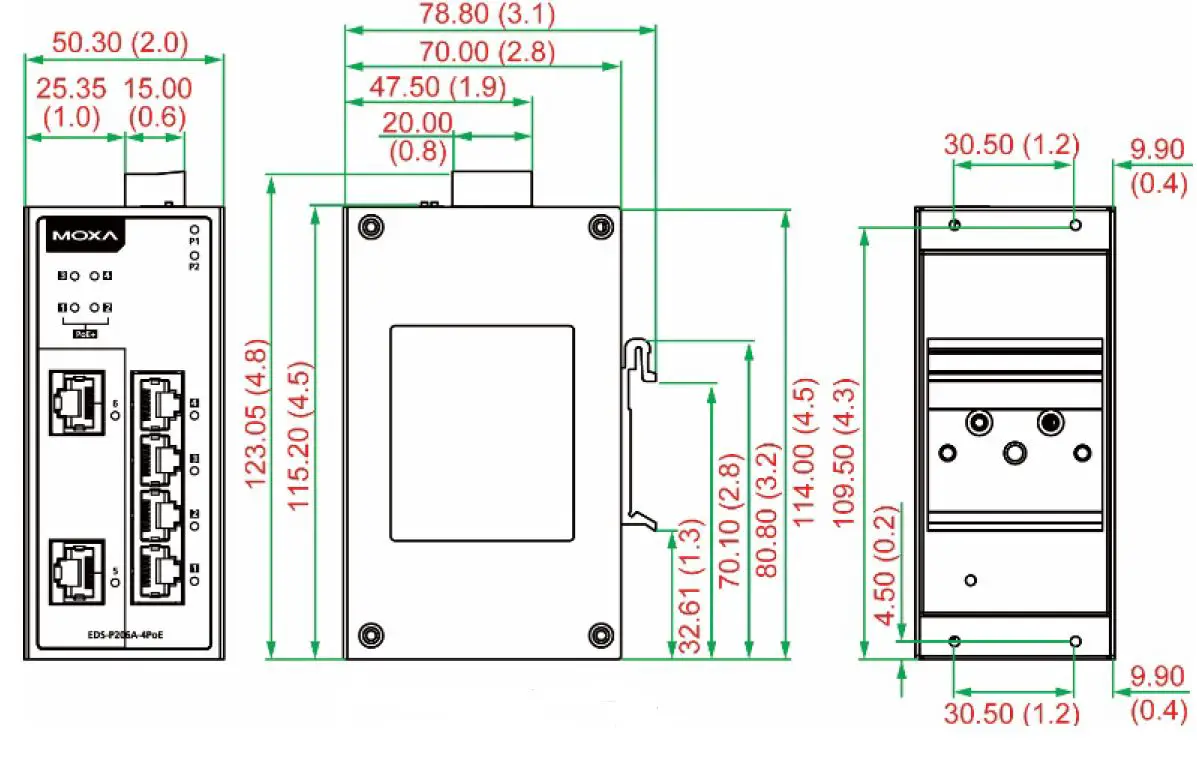

DIN-Rail Mounting
The aluminum DIN-Rail attachment plate should already be fixed to the back panel of the EDS when you take it out of the box. If you need to reattach the DIN-Rail attachment plate, make sure the stiff metal spring is situated towards the top, as shown in the figures below.
STEP 1: Insert the top of the DIN-Rail into the slot just below the stiff metal spring.
STEP 2: The DIN-Rail attachment unit will snap into place as shown below.
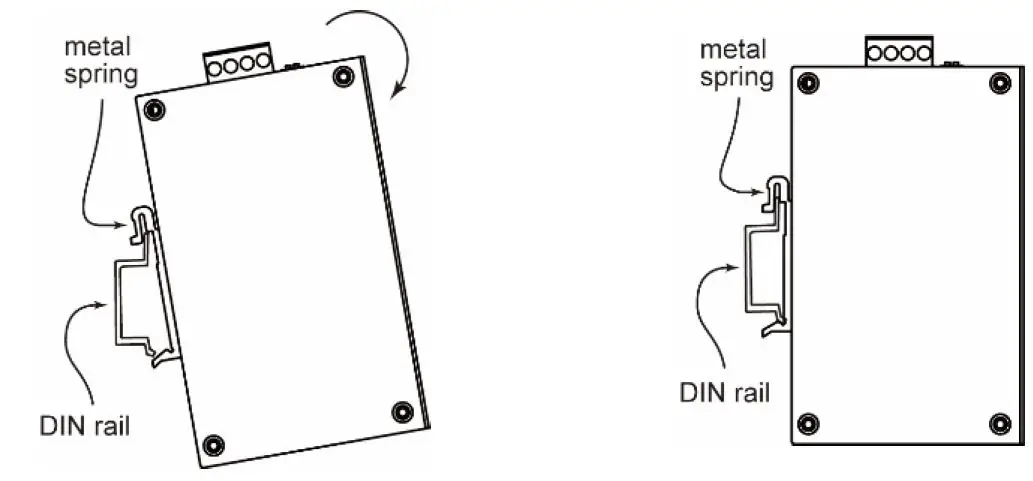
To remove the EDS from the DIN-Rail, reverse Steps 1 and 2 above.
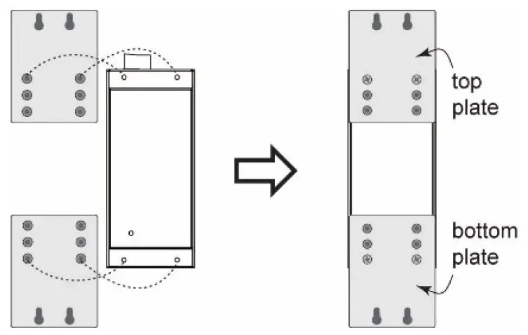
Wall Mounting (optional)
For some applications, you will find it convenient to mount the EDS-P206A-4PoE on the wall, as shown in the following figures.
- Remove the aluminum DIN-Rail attachment plate from the EDS-P206A-4PoE’s rear panel, and then attach the wall mount plates as shown in the diagram at the right.

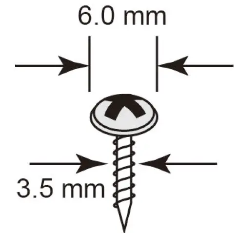
- Mounting the EDS-P206A-4PoE on the wall requires 4 screws. Use the switch, with wall mount plates attached, as a guide to mark the correct locations of the 4 screws. The heads of the screws should be less than 6.0 mm in diameter, and the shafts should be less than 3.5 mm in diameter, as shown in the figure at the right.
NOTE Before tightening the screws into the wall, make sure the screw head and shank size are suitable by inserting the screw into one of the keyhole-shaped apertures of the wall mounting plates.
Do not screw the screws in completely—leave about 2 mm to allow room for sliding the wall mount panel between the wall and the screws.
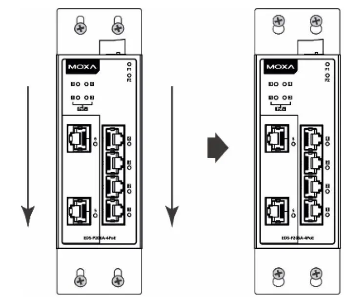
- Once the screws are fixed in the wall, insert the four screw heads through the large parts of the keyhole-shaped apertures, and then slide the EDS-P206A-4PoE downwards, as indicated. Tighten the four screws for added stability.
Wiring Requirements
WARNING
Safety First! Turn the power off before disconnecting modules or wires. The correct power supply voltage is listed on the product label. Check the voltage of your power source to make sure that you are using the correct voltage. Do NOT use a voltage greater than what is specified on the product label.
Safety First! Calculate the maximum possible current in each power wire and common wire. Observe all electrical codes dictating the maximum current allowable for each wire size. If the current goes above the maximum ratings, the wiring could overheat, causing serious damage to your equipment.
You should also pay attention to the following points:
- Use separate paths to route wiring for power and devices. If power wiring and device wiring paths must cross, make sure the wires are perpendicular at the intersection point.
NOTE: Do not run signal or communications wiring and power wiring in the same wire conduit. To avoid interference, wires with different signal characteristics should be routed separately. - You can use the type of signal transmitted through a wire to determine which wires should be kept separate. The rule of thumb is that wiring that shares similar electrical characteristics can be bundled together.
- Keep input wiring and output wiring separated.
- We strongly advise labeling the wiring to all devices in the system.
Grounding the EtherDevice Switch
Grounding and wire routing help limit the effects of noise due to electromagnetic interference (EMI). Run the ground connection from the ground screw to the grounding surface prior to connecting devices.
ATTENTION This product is intended to be mounted to a well-grounded mounting surface such as a metal panel.
Wiring the Redundant Power Inputs
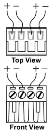
The top two contacts and the bottom two contacts of the 4-contact terminal block connector on the EDS’s top panel are used for the EDS’s two DC inputs. Top and front views of one of the terminal block connectors are shown here.
- Insert the negative/positive DC wires into the V-/V+ terminals.
- To keep the DC wires from pulling loose, use a small flat-blade screwdriver to tighten the wire-clamp screws on the front of the terminal block connector.
- Insert the plastic terminal block connector prongs into the terminal block receptor, which is located on EDS’s top panel.
ATTENTION Before connecting the EtherDevice Switch to the DC power inputs, make sure the DC power source voltage is stable.
Communication Connections
The EDS-P206A-4PoE switches have 4, 5, or 6 10/100BaseT(X) Ethernet ports, and 2, 1, or 0 (zero) 100BaseFX multi/single-mode (SC/ST-type connector) fiber ports.
10/100BaseT(X) Ethernet Port Connection
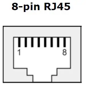
10/100BaseT(X) ports located on the EDS’s front panel are used to connect to Ethernet-enabled devices. Below we show pinouts for both MDI (NIC-type) ports and MDI-X (HUB/Switch-type) ports, and also show cable wiring diagrams for straight-through and cross-over Ethernet cables.
MDI Port Pinouts
| Pin | Signal |
| 1 | Tx+ |
| 2 | Tx- |
| 3 | Rx+ |
| 6 | Rx- |
MDI-X Port Pinouts
| Pin | Signal |
| 1 | Rx+ |
| 2 | Rx- |
| 3 | Tx+ |
| 6 | Tx- |
PoE 10/100BaseT(X) Ethernet Port Connection
PoE 10/100BaseT(X) ports located on the EDS switch’s front panel are used to connect to PoE-enabled devices. The pinout follows the “Alternative A, MDI mode” of 802.3af/at standards. Please see the details in the following table.
PoE Port Pinout
| Pin | Data | Power |
| 1 | Tx+ | V+ |
| 2 | Tx- | V+ |
| 3 | Rx+ | V- |
| 6 | Rx- | V- |
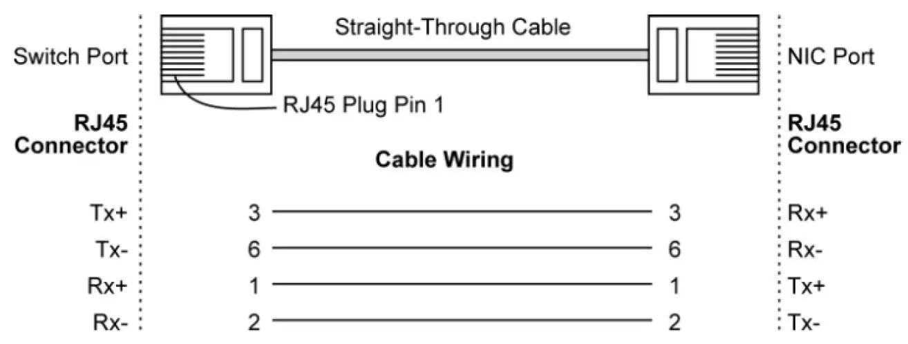
NOTE According to IEEE 802.3af/at standards, the PD shall be implemented to be insensitive to the polarity of the power supply and shall be able to operate per MDI mode and MDI-X mode. However, some PDs only support MDI mode or MDI-X mode only. The following figure shows how to select the correct cable between the PD and EDS-P206A-4POE.
RJ45 (8-pin) to RJ45 (8-pin) Straight-Through Cable Wiring
RJ45 (8-pin) to RJ45 (8-pin) Cross-Over Cable Wiring
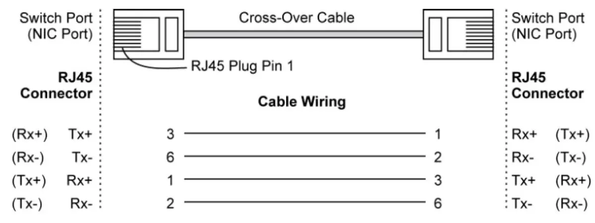
NOTE If the PD only supports MDI-X mode (V-, V-, V+, V+ for pins 1, 2, 3, 6), choose a cross-over Ethernet cable to connect the PD and the EDS switch. If the PD only supports MDI mode (V+, V+, V-, V- for pins 1, 2, 3, 6), choose a straight-through Ethernet cable between the PD and the EDS-P206A-4PoE switch.
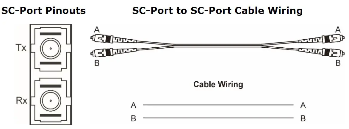
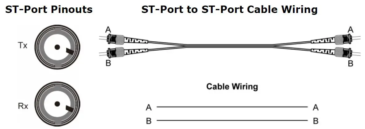
100BaseFX Ethernet Port Connection
The concept behind the SC/ST port and cable is straightforward. Suppose you are connecting devices I and II; contrary to electrical signals, optical signals do not require a circuit in order to transmit data. Consequently, one of the optical lines is used to transmit data from device I to device II, and the other optical line is used transmit data from device II to device I, for full-duplex transmission.
Remember to connect the Tx (transmit) port of device I to the Rx (receive) port of device II, and the Rx (receive) port of device I to the Tx (transmit) port of device II. If you make your own cable, we suggest labeling the two sides of the same line with the same letter (A-to-A and B-to-B, as shown below, or A1-to-A2 and B1-to-B2).
ATTENTION This is a Class 1 Laser/LED product. To avoid causing serious damage to your eyes, do not stare directly into the Laser Beam.
Redundant Power Inputs
Both power inputs can be connected simultaneously to live DC power sources. If one power source fails, the other live source acts as a backup, and automatically supplies all of the EDS’s power needs.
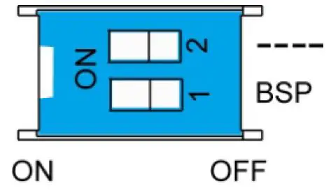
DIP Switch Settings
The default setting for each DIP Switch is OFF. The following table explains the effect of setting the DIP Switches to the ON positions.
| DIP Switch | Setting | Description |
| – | – | Serves no function (reserved for future use). |
| BSP | ON | Enables broadcast storm protection |
| OFF | Disables broadcast storm protection |
ATTENTION To actively update DIP switch settings, power off and then power on the EDS.
LED Indicators
The front panel of the EDS switches contains several LED indicators. The function of each LED is described in the following table.
| LED | Color | State | Description |
| P1 | AMBER | On | Power is being supplied to power input P1. |
| Off | Power is not being supplied to power input P1. | ||
| P2 | AMBER | On | Power is being supplied to power input P2. |
| Off | Power is not being supplied to power input P2. | ||
|
10/100 | AMBER | On | TP port’s 10 Mbps link is active. |
| Blinking | Data is being transmitted at 10 Mbps. | ||
| Off | TP port’s 10 Mbps link is inactive. | ||
| GREEN | On | TP port’s 100 Mbps link is active. | |
| Blinking | Data is being transmitted at 100 Mbps. | ||
| Off | TP port’s 100 Mbps link is inactive. | ||
|
PoE+ |
AMBER | On | The PoE device is connected by the IEEE 802.3af standard |
| Blinking | The PoE power is shut off because there is insufficient power | ||
| Off | No PoE power output or no PoE connected devices | ||
| Green | On | The PoE device is connected by the IEEE 802.3at standard | |
| Off | No PoE power output or no PoE connected devices | ||
|
Red | Blinking | PoE failure: -1 time/sec: PoE standard detection failure -2 times/sec: PoE current overload | |
| Off | No PoE failure |
Auto MDI/MDI-X Connection
The Auto MDI/MDI-X function allows users to connect the EDS’s 10/100BaseTX ports to any kind of Ethernet device, without needing to pay attention to the type of Ethernet cable being used for the connection. This means that you can use either a straight-through cable or cross-over cable to connect the EDS to Ethernet devices.
Dual Speed Functionality and Switching
The Moxa EtherDevice Switch’s 10/100 Mbps switched RJ45 port auto negotiates with the connected device for the fastest data transmission rate supported by both devices. All models of Moxa EtherDevice Switch are plug-and-play devices, so that software configuration is not required at installation, or during maintenance. The half/full duplex mode for the switched RJ45 ports is user dependent and changes (by auto-negotiation) to full or half duplex, depending on which transmission speed is supported by the attached device.
Broadcast Storm Protection
The EDS-P206A-4PoE Series has a built-in algorithm for limiting the amount of broadcast packets through the switch. This function is by default disabled and can be enabled by turning on the DIP switch labeled “BSP” on the top cover. If the broadcast storm protection algorithm detects more than 1k broadcast frames per second, then the switch will be suppressed from receiving broadcast frames for a period of 2 ms to prevent any further flooding.
Switching, Filtering, and Forwarding
Each time a packet arrives at one of the switched ports, a decision is made to either filter or forward the packet. Packets with source and destination addresses belonging to the same port segment will be filtered, constraining those packets to one port, and relieving the rest of the network from the need to process them. A packet with destination address on another port segment will be forwarded to the appropriate port, and will not be sent to ports where it is not needed. Packets that are used in maintaining the operation of the network (such as the occasional multi-cast packet) are forwarded to all ports. The EDS operates in the store-and-forward switching mode, which eliminates bad packets and enables peak performance to be achieved when there is heavy traffic on the network.
Switching and Address Learning
The EDS has an address table that can hold up to 1024 addresses, which makes it suitable for use with large networks. The address tables are self-learning, so that as nodes are added or removed, or moved from one segment to another, the EDS automatically keeps up with new node locations. An address-aging algorithm causes the least-used addresses to be deleted in favor of newer, more frequently used addresses. To reset the address buffer, power down the unit and then power it back up.
Auto-Negotiation and Speed Sensing
All of the EDS’s RJ45 Ethernet ports independently support auto-negotiation for speeds in the 10BaseT and 100BaseTX modes, with operation according to the IEEE 802.3u standard. This means that some nodes could be operating at 10 Mbps, while at the same time, other nodes are operating at 100 Mbps. Auto-negotiation takes place when an RJ45 cable connection is made, and then each time a LINK is enabled. The EDS advertises its capability for using either 10 Mbps or 100 Mbps transmission speeds, with the device at the other end of the cable expected to advertise in a similar manner. Depending on what type of device is connected, this will result in agreement to operate at a speed of either 10 Mbps or 100 Mbps. If an EDS RJ45 Ethernet port is connected to a non-negotiating device, it will default to 10 Mbps speed and half-duplex mode, as required by the IEEE 802.3u standard.
Total Power Budget
For the total power budget, the EDS-P206A-4PoE will have 62 W at 12-17 VDC input, and 120 W at 18-57 VDC input. The total power budget is the total amount of reserved PoE power based on the PoE class of PoE device. If a newly connected PoE device causes the total reserved power to exceed the total power budget, the newly connected PoE device will be denied power.
| Input Voltage | Total Power Budget |
| 12 VDC (12-17 VDC) | 62 W |
| 24 VDC (18-35 VDC) | 120 W |
| 48 VDC (36-57 VDC) | 120 W |
| PoE Class | Reserved Power |
| 0 | 15.4 W |
| 1 | 4.0 W |
| 2 | 7.0 W |
| 3 | 15.4 W |
| 4 | 30 W |
Specifications
| Technology | |
| Standards | IEEE 802.3 for 10BaseT, IEEE 802.3u for 100BaseT(X) and 100BaseFX, IEEE 802.3x for Flow Control IEEE 802.3af for PoE IEEE 802.3at for PoE+ |
| Processing Type | Store and Forward |
| Flow Control | IEEE 802.3x flow control, back pressure flow control |
| Interface | |
| RJ45 Ports | 10/100BaseT(X) auto negotiation speed, F/H duplex mode, and auto MDI/MDI-X connection |
| Fiber Ports | 100BaseFX ports (SC/ST connector, multi/single-mode) |
| LED Indicators | P1, P2 (Power), 10/100M (TP port), and 100M (fiber port), PoE |
| DIP Switch | enable/disable broadcast storm protection |
| Optical Fiber | |||||
| 100BaseFX | |||||
| Multi-mode | Single-mode | ||||
| Fiber Cable Type | OM1 | 50/125 μm | G.652 | ||
| 800 MHz*km | |||||
| Typical Distance | 4 km | 5 km | 40 km | ||
| Wavelength | Typical (nm) | 1300 | 1310 | ||
| TX Range (nm) | 1260 to 1360 | 1280 to 1340 | |||
| RX Range (nm) | 1100 to 1600 | 1100 to 1600 | |||
| Optical Power | TX Range (dBm) | -10 to -20 | 0 to -5 | ||
| RX Range (dBm) | -3 to -32 | -3 to -34 | |||
| Link Budget (dB) | 12 | 29 | |||
| Dispersion Penalty (dB) | 3 | 1 | |||
| Note: When connecting a single-mode fiber, we recommend using an attenuator to prevent damage caused by excessive optical power. | |||||
| Typical Distance | To reach the typical distance of the specified fiber transceiver, please refer to the following formula: Link budget(dB) > dispersion penalty(dB) + total link loss(dB) | ||||
| PoE | |||||
| Total Power Budget | 62 W @ 12 VDC (12-17 VDC) 120 W @ 24/48 VDC (18-57 VDC) | ||||
| PoE Output Voltage | 50 VDC @ 12/24/48 VDC power input | ||||
| PoE Output Power | 15.4 W for 802.3af, 30 W for 802.3at | ||||
| PoE Output Current | 350 mA for 802.3af, 600 mA for 802.3at | ||||
| Overload Current Protection (at the port) | Supported | ||||
| PoE Pinout | Mode A: Pair 1, 2 (V+); Pair 3, 6 (V-) | ||||
| Power | |||||
| Input Voltage | 12/24/48 VDC, redundant dual inputs | ||||
| Operating Voltage | 12 to 57 VDC | ||||
| Rated Current | 6.19A @ 12VDC, 5.55A @ 24 VDC, 2.71A @ 48 VDC | ||||
| Power Consumption | 13.2 W max., without PDs’ consumption | ||||
| Inrush Current | 64.56 A @ 48 VDC (0.1 – 1ms) | ||||
| Electrical Isolation | 2250 VDC to chassis for 60 s | ||||
| Heat Dissipation | 45.03 BTU/h | ||||
| Overload Current Protection (at the input) | Supported | ||||
| Reverse Polarity Protection | Supported | ||||
| Connection | 1 removable 4-contact terminal block | ||||
| Note: We strongly recommend using an isolated power supply with maximum output current of 7.5 A due to the power de-rating issue of the power supply at high operating temperatures. Moreover, without galvanic isolation between the redundant power inputs of this device, the V1+ and V2+ should use the same voltage. | |||||
| Physical Characteristics | |
| Housing | Metal, IP30 protection |
| Dimensions | 50 x 114 x 70 mm |
| Weight | 275 g |
| Installation | DIN-Rail Mounting, Wall Mounting (with optional kit) |
| Environmental Limits | |
| Operating Temperature | Standard models: -10 to 60°C (32 to 140°F) Wide temp. models: -40 to 75°C (-40 to 167°F) |
| Storage Temperature | -40 to 85°C (-40 to 185°F) |
| Ambient Relative Humidity | 5 to 95% (non-condensing) |
| Regulatory Approvals | |
| Safety | UL508 |
| EMI | FCC Part 15, CISPR (EN55032) class A |
| EMS | IEC 61000-4-2 ESD: Contact 6 kV; Air 8 kV IEC 61000-4-3 RS: 20 V/m (80 MHz to 1 GHz) IEC 61000-4-4 EFT: Power 2 kV; Signal 1 kV IEC 61000-4-5 Surge: Power 2 kV; Signal 2 kV IEC 61000-4-6 CS: 10 V IEC 61000-4-8 |
| Shock | IEC 60068-2-27 |
| Freefall | IEC 60068-2-32 |
| Vibration | IEC 60068-2-6 |
| Warranty | |
| Time Period | 5 years |
| Details | www.moxa.com/warranty |
Patent
http://www.moxa.com/doc/operations/Moxa_Patent_Marking.pdf


