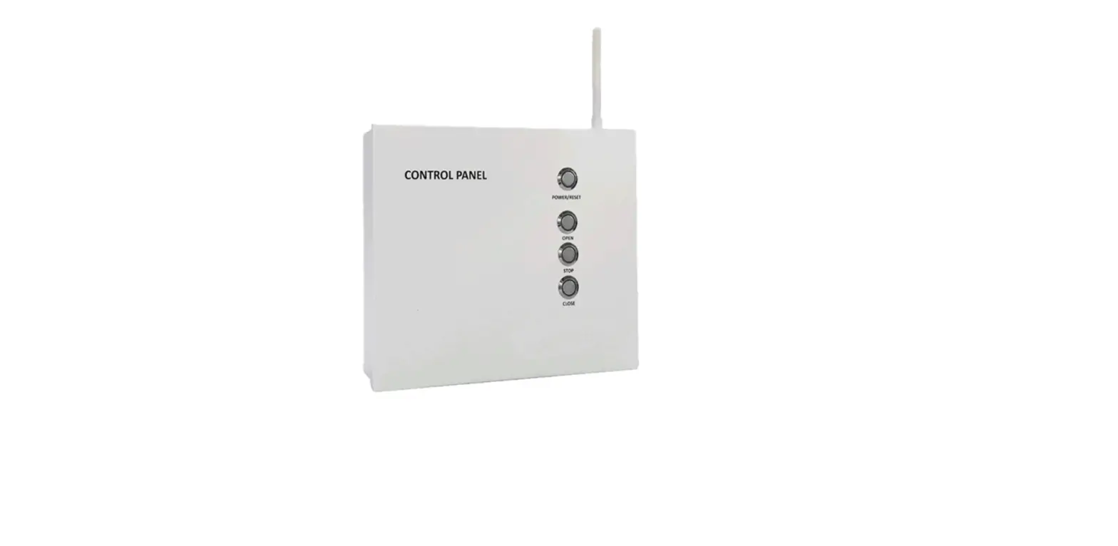
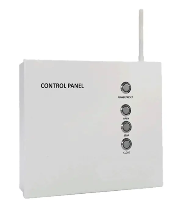
Autovent Systems AV-CP6 Series AV Electric Vent Opener
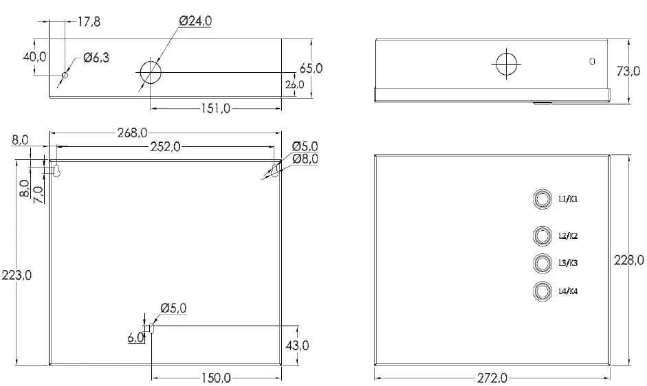
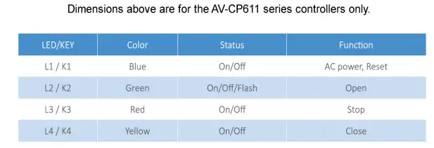
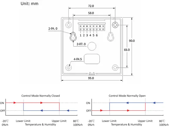
Dimensions


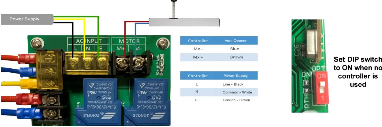
AV-CP6 Series Control Panel Wiring 
AV-TH001 Temperature / Humidity Control Wiring
The wiring method in Figure 3 is commonly used in applications where 4 or less openers will be installed with less than 40’ of total wiring run. 14 gauge wire can be used in this scenario. Figure 4 divides the power to the openers into multiple lines. It is recommended for applications of 4 or more openers and/or wiring runs over 40’. 14 gauge wire can still be used with this method for up to 8 openers with a wiring run of 40’ or less (per line). 12 gauge wire should be used for longer runs. 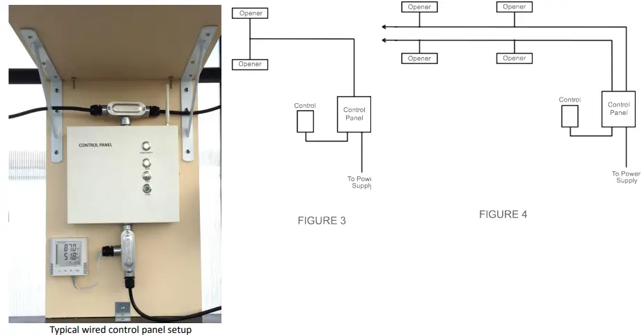
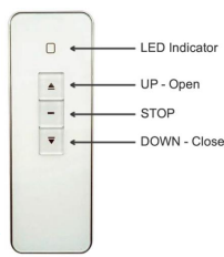
AV-RT111 Remote Control Instructions
Pairing Remote with Control Panel
- Power the control panel on or press reset if already on. Press and hold the STOP button for 5 seconds.
- Press UP on the remote for 15 seconds. The LED on the remote should flash 3 times and turn off during this process.
Remove Pairing with Control Panel
- Power the control panel on or press reset if already on. Press and hold the STOP button for 5 seconds.
- Press DOWN on the remote for 15 seconds. The LED on the remote should flash 3 times and turn off during this process.

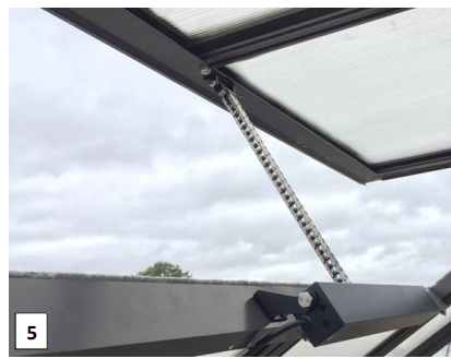
AV-SCE Vent Opener Instructions 
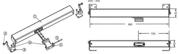
- Actuator
- Hexagonal head screw
- Fixed Bracket
- Fixed Holder
- Pin
- M5 self-tapping screw
Opener Specifications
- Voltage: 24V DC
- Max Current: 1 amp
- Max Lifting Weight: 55 lbs.
- Arm Travel Distance: 12″
- Time to Open / Close: 35 seconds
- Operating Temp Range: -4F to 149F
- Attach the fixed brackets to the actuator. Place the opener on the frame where the arm will attach as close the center of the vent as possible, and mark the location of both brackets.
- Unscrew the fixed brackets, and place them where marked on the frame (mounting position shown is for Cross Country greenhouses and optimal position may vary for other brands).
- Use the provided Hex head screws starting with the center hole. They are self-tapping so no pre-drilling is needed. For Cross Country greenhouses the top hole is not used because the screw will damage the covering/glazing on most models.
- Mount the actuator to the fixed brackets, and place the fixed arm holder on the vent where the arm will make contact when extended. Use the Phillips head screws to attach the fixed arm holder to the vent frame. Press open on the control panel or remote to move the head of the arm in position to secure it to the holder with the attached bolt.
- Fully open and close the vent to make sure it operates smoothly. Repeat this process for the rest of the openers.


AV-TH001 Temperature/Humidity Controller Instructions
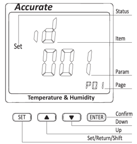
Operation instructions
- On the initial page, press “SET” button and enter defaulted password “0000”
- Press “UP” “DOWN” keys to switch T D, ID, Baud, DOI, D02, Date and Time
- For a total of 22 setting pages, press “UP” “DOWN” keys to select the item to set The “ENTER” key to set the Press parameter on the page
- After the parameter is adjusted, press “ENTER” button to save the settings
- Press the “SET” key to return to the initial page

- The AV-TH001 can control openers based on humidity or temperature. You can select both a high and low limit for either humidity or temperature. DO NOT ENABLE BOTH humidity and temperature. The autovent system will not operate correctly if you do.
For optimal operation and accuracy:
- Do not install directly against an outside wall or in direct sunlight.
- Protect from direct contact with water. Do not place in direct path of misting or fogging system.
AV-TH001 Setting Pages and Parameters
| Page | Parameter | Description | Default | Notes |
| P:01 | Address | 1-247 | 1 | Use default setting |
| P:02 | Baud Rate | 1200-19200 | 19.2 | Use default setting |
| P:03 | Check Mode | n81/o81/e81 | n81 | Use default setting |
| P:04 | Temp Units | C: Celsius F: Fahrenheit | C | Change to F if desired |
| P:05 | DO1 Usage | Ctrl: Control Mode Alarm: Alarm Mode | ctrl | Use default setting |
| P:06 | DO2 Usage | ctrl | Use default setting | |
| P:07 | DO1 Enable (Temperature) | 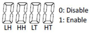 | 0011 | Change to 0000 if you want to disable temperature control |
| P:08 | DO2 Enable (Humidity) | 1100 | Change to 0000 if you want to disable humidity control | |
| P:09 | DO1 Normal State | OFF: Normally Open ON: Normally Closed | OFF | Opens above HT setpoint (Cooling) |
| P:10 | DO2 Normal State | OFF | Opens above HH setpoint (Dehumidify) | |
| P:11 | High Temp (HT) | High-Temperature Limit | optional | Set the temperature you want the vents to open. Units are in Celsius |
| P:12 | Low Temp (LT) | Low-Temperature Limit | optional | Set the temperature you want the vents to close. Units are in Celsius |
| P:13 | High Humidity (HH) | High Humidity Limit | optional | Set the humidity % you want the vents to open. |
| P:14 | Low Humidity (LH) | Low Humidity Limit | optional | Set the humidity % you want the vents to close. |
| P:15 | Temp Buffer Value | Temperature Buffer: 0.1C | 0.1 | Use default setting |
| P:16 | Humidity Buffer Value | Humidity Buffer: 1rh% | 1 | Use default setting |
| P:17 | Date Setting | Year – Month – Day | optional | Set the current date |
| P:18 | Time Setting | Hour – Minute – Second | optional | Set the current time |
| P:19 | Password | Security Lockout Feature: 0000-9999 | 0000 | If you change the password, make sure you write it down! |
| P:20 | Recording Cycle Setting | 1-1440 minutes | 1 | Use default setting |
| P:21 | None | 1234 | Use default setting | |
| P:22 | None | 20 | Use default setting |


